Advertisement
Quick Links
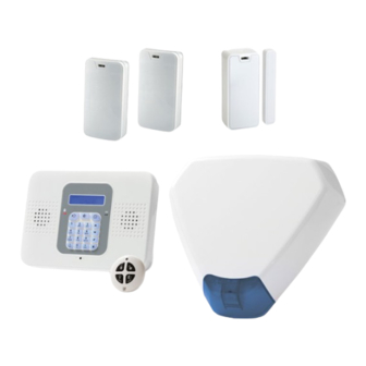
The GT 600 / 601
Control Panel
Quick Start Instructions
Download the complete GT 600 / 601 Installation Manual at
www.riscogroup.co.uk
RISCO Group UK Ltd
Tel: 0161 655 5500 Fax: 0161 655 5501
Int Tel: +44 161 655 5500 Fax: +44 161 655 5501
Internet: www.riscogroup.co.uk
e-mail: sales@riscogroup.co.uk
Technical Support Tel: 0161 655 5600
Technical Support Fax: 0161 655 5610
(Mon - Fri 08:30-1730)
This Quick Start Guide gives brief installation information for the GT 600 / 601
Control Panels RISCO Group UK Ltd reserve the right to amend the software and features
without prior notice
5IN1785
PR600601QS_3_ Rev1.2
Advertisement

Subscribe to Our Youtube Channel
Related Manuals for Risco GT 600


Summary of Contents for Risco GT 600
- Page 1 Technical Support Fax: 0161 655 5610 (Mon - Fri 08:30-1730) This Quick Start Guide gives brief installation information for the GT 600 / 601 Control Panels RISCO Group UK Ltd reserve the right to amend the software and features without prior notice 5IN1785 PR600601QS_3_ Rev1.2...
- Page 2 Replacement fuses should be of the same type and rating conforming to IEC 127. The GT 600 / 601 Control Panels are fitted with resettable fuses. The areas protected are Battery, Aux, Bell, Keypad and Comms. In the event of a fuse tripping or an input/ output not working, remove the source of the load and check wiring for shorts.
-
Page 3: Mains Supply Connection
Introduction The GT 600 / 601 Control Panels are microprocessor based units that have been designed to be suitable for all types of domestic and commercial installations. All zones are fully programmable by the engineer. On power up / reset, the Control Panel can be set to the old BS, EN2 (Grade 2) or EN3 (Grade 3) operating standards. - Page 4 Gardtec 600 PCB Fitting Instructions Fitting the 600 PCB (plastic case) Make sure all mains power is disconnected before fitting the PCB. After fitting the case to the wall, and feeding the cables through the relevant entries, mount the 600 PCB as shown in the figure 1:- 1.
- Page 5 Fig1. 600 PCB (plastic case). Page 4...
- Page 6 Output Terminal Descriptions Speaker Terminals This pair of terminals provide connection for:- System Speaker(s) Optional 16/32 Ohm Panel Speaker A speaker is supplied in each keypad. If any additional speakers are fitted they should present a minimum impedance of 16 Ohm. PGM 1, 2 &...
- Page 7 6 Wire Keypads 6 Wire Keypads can be used with the GT 600 / 601 Control Panel. Please refer to the installation instructions supplied with the 6 wire keypads. Please note that only one type of keypad can be used. 4 wire and 6 wire keypads cannot be mixed.
- Page 8 Digi Modem - The GT 600 / 601 control panels feature an onboard Digi modem. The Digi provides all the features of an eight channel communicator whilst the Modem provides facilities for Gardtec Remote Upload/Download software package. Vo-Comm - (If fitted) Is a method of transmitting signals to a standard land-line or mobile telephone, giving information regarding the status of your security system.
- Page 9 R TMP SAB TMP F TMP +12V BELL+ BELLHOLD- BELL- STROBE- Novagard 2G/4G GT 600 / 601 Control Panel (Strobe terminals omitted) Fig6. Control Panel Input (Zone) Connections N/C Devices N/C Devices N/C Devices N/C Devices N/C Devices N/C Devices...
- Page 10 Zone/Output/ID Expander Card Connections Upto 4 zone expander cards (or 1 ID Expander card) can be fitted to the 600. Up to 16 zone expander cards (or 2 ID Expander card) can be fitted to the 601. These are all fitted to a common expander bus via a serial connection lead (part No. 1CB 6046). This lead is fitted to the plug on the front of the control panel PCB and the cards wired as shown below.
- Page 11 Zone Expander (ZEX) Wiring Modes Three wiring modes may be programmed for each ZEX these are. 4 Wire Gives 4 zones AZE 1 - AZE 4 and four tampers TZE 1 - TZE 4 2 Wire Gives 8 zones AZE1 - AZE 4 then TZE 1 - TZE 4 End Of Line Gives 8 End Of Line zones AZE 1 - AZE 4 then TZE 1 - TZE 4 All AZE zones are positive loops and all TZE zones are negative loops.
- Page 12 ID Expander Detector Wiring One ID Expander Card may be fitted to the GT 600 control panel giving 8 panel zones plus up to 30 ID zones using industry standard ID Biscuits or ID Detectors. ID zones numbers are 21 through to 50. Two ID Expander Cards may be fitted to the GT 601 Control Panel.
- Page 13 GT 600 / 601 Connection Details If powering up the Control Panel with battery only, connect battery and short out JP1 for approx. 5 seconds. Key pad and Control Panel will then become active. On the GT 600 the BAT. jumper can be found under the pcb plastic cover.
-
Page 14: Initial Power Up
Initial Power Up When the Control Panel is powered up it will be either set or unset dependent on the state of the Control Panel when it was powered down. The factory default state will be unset. Reset to Default Modes Note: It is ESSENTIAL that a 4 6 Yes No reset is done to all new systems before commencement of programming. -
Page 15: Engineer Programming Mode
Engineer Programming Although LED keypads may be used, ONLY the LCD keypads can be used to programme the GT 600 / 601 Control Panels. To enter the engineer programming mode follow the steps outlined below:- 1. Remove all power from the system for at least 10 seconds. - Page 16 Select PD6662 The display will then show:- 1: 2004 2: 2010 From Control Panel Version 2 ONLY. 5. Select either 1 or 2 depending on which standard you require. Please WAIT The display will show:- This may show for several minutes. Enter Authorisor The display will then show:- Code .
-
Page 17: Factory Default Codes
Note: Throughout the programming routine you may use the 0 (zero) Key to escape back one level. This does not apply when a numeric entry is expected, in this case complete the input before using the 0 Key to escape. Factory Default Codes: Engineer BS / EN2 - 1234... - Page 18 Available Headers & Options Below is shown the Headers (menu numbers, see page 19) that are available and the options that appear under each Header. Program Zones... Program Digicom... Zone Types Digicom Type or Test Zone Descriptors Vo-Comm Zone Wiring Digicom Delay / Part Zone Attributes Digicom Channels...
- Page 19 Although LED keypads may be used Expander 3 Output 4 Mode ONLY the LCD keypads can be used Expander 4 Output 1 Mode to programme the GT 600 / 601 Expander 4 Output 2 Mode Control Panel. Expander 4 Output 3 Mode...
-
Page 20: Zone Defaults
With a Header showing, key in the appropriate menu number, then press Yes. For a full list of Common Options please refer to the GT 600 / 601 Engineer’s Reference Guide which is available on the web site. - Page 21 Programming Alarm Confirm The first option will be: Confirm Time Window (default = 60) This time window may be programmed between 1 and 120 minutes. To comply the required time should be between 30 and 60 minutes. Confirm on Entry (default = On) This option may be programmed to On or Off.
- Page 22 Confirm Secondary Time Window (default = 60 minutes) This time window may be programmed between 1 and 120 minutes we would suggest a time between 30 and 60 minutes but should typically be the same time as the confirm time window. This option affects zones that have been allocated as secondary zones only.
- Page 23 Secondary type zones would be used for detectors that may be deemed as having an over sensitive nature, this will stop unwanted user call-outs. Zones that are entered as Secondary will follow the chain of events below. During a set period triggering a Secondary Zone will start the Secondary Time Window.
- Page 24 Keypad Zone Wiring Details Fig13. Page 23...
- Page 25 R E S I S T O R C O L O U R C O D E S Brown Brown Yellow Blue Blue Violet Violet Grey Orange Orange Orange Brown Brown Brown Brown Brown Fig14. Radio Expander Wiring & Switch Settings Connect cable between Con 4 on the 600 / 601 PCB and the Radio Receiver.
- Page 26 Typical Wiring Modes Where Anti-Mask detectors are used, one of the below wiring modes may be utilised. ELF1 wiring is used for detectors that have a Alarm Tamper Fault/Mask relay output (a pair of terminals) for Fault or Mask. The installer should check what output type the detectors are, noting that all detectors should be of the same type with regards to the Fault / Mask output.
- Page 27 Notes: Page 26...
- Page 28 Notes: Page 27...
Need help?
Do you have a question about the GT 600 and is the answer not in the manual?
Questions and answers