Table of Contents
Advertisement
Advertisement
Table of Contents

Related Manuals for Risco ProSYS 128


Summary of Contents for Risco ProSYS 128
-
Page 1: User Guide
User Guide For use with ProSYS 40, and ProSYS 128... - Page 2 RTTE Declaration Of Conformity Hereby, RISCO Group declares that this control panel (ProSYS 128, ProSYS 40), with wired accessories (including cables) and wireless accessories, is in compliance with the essential requirements and other relevant provisions of Directive 1999/5/EC. For the CE Declaration of Conformity please refer to our website: www.riscogroup.com.
-
Page 3: Table Of Contents
Table of Contents SUMMARY OF USER COMMANDS..........6 CHAPTER 1: INTRODUCTION............9 Operating the System ............. 10 The ProSYS Family ..............11 CHAPTER 2: YOUR KEYPAD............12 The keypad................12 LED Indicators ................. 12 Power LED................13 Set LED................13 Ready LED................ - Page 4 Wireless 4-Button Key Fob Setting........27 Unsetting.................. 27 Unsetting the System............27 Unsetting After an Alarm............. 28 Resetting after an Alarm ............. 29 Partition Unsetting .............. 30 Duress Unsetting ..............31 Disabling a Fire Alarm (Switch Auxiliary)......32 CHAPTER 4: OMITTING A ZONE ..........33 CHAPTER 5: ACTIVATING PROGRAMMABLE OUTPUTS ..
- Page 5 Defining a User Limitation Program........51 CHAPTER 11: PROGRAMMING FUNCTION KEYS ..... 53 CHAPTER 12: PROXIMITY KEYPAD ..........56 Adding a New Proximity Tag..........56 Deleting a Proximity Tag by the User Serial Number ..57 Deleting a Proximity Tag by the User Tag ......58 Using a Proximity Tag.............
-
Page 6: Summary Of User Commands
Summary of User Commands Full Set Hold the tag close to the keypad's keys -OR- Code> Part Setting Code> Group Setting Code>A/B/ Partition Full Hold the tag close to the keypad's keys > Setting Partition No. > -OR- Code> > Partition No. > Partition Part Code>... - Page 7 View Alarm >[3]>[2]>[Code]> Memory View Zone Status >[3]>[4]>[Code]> View Event Memory >[3]>[5]>[Manager Code]> Bell/Strobe/Keypad >[4]>[Code]> >[1] Test Zone Testing (Walk >[4]>[Grand Master Code]> Test) >[0] Local Chime On/Off >[4]>[Code]> >[4]/[3] Edit User Code >[5]>[Code]> >[1] Edit Time >[6]>[Grand Master Code]> >[1] Edit Date >[6]>[Grand Master Code]>...
- Page 8 ProSYS User Guide...
-
Page 9: Chapter 1: Introduction
ProSYS, where it can be conveniently turned on and off automatically or by user command from any system keypad, or wireless keyfob, described on page 35. In addition, the ProSYS supports the following optional RISCO Group devices: Advanced Communication Module (ACM) that enables the system to operate over the IP network. -
Page 10: Operating The System
Event announcement, as described in the Voice Module Programming and Operations Manual If your system is equipped with RISCO Group's GSM(AGM)/GPRS module it can provide information about the system by SMS and enable to operate the system using SMS commands for setting the system, unsetting the system and more. -
Page 11: The Prosys Family
The ProSYS Family This manual applies for both ProSYS 40 ProSYS 128 panels. The following table, lists the number of features in each type of panel. Feature ProSYS 40 ProSYS 128 Total Zones 8 - 40 8 - 128 User Codes... -
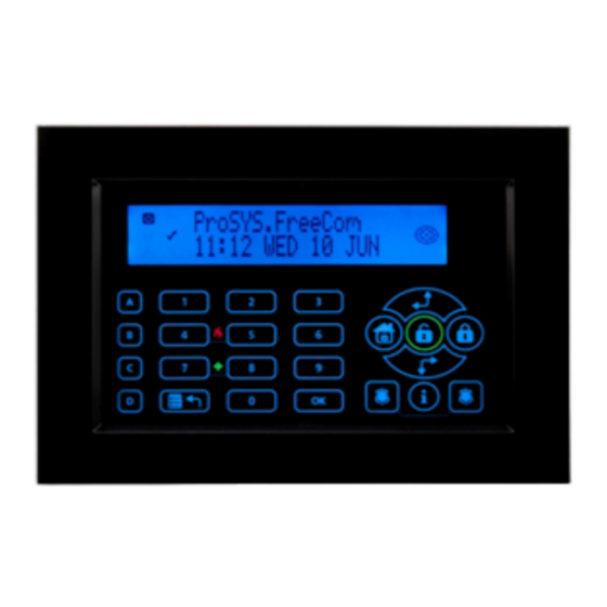
Page 12: Chapter 2: Your Keypad
Chapter 2: Your Keypad As a security system user, you will perform most operations using the keypad. This section discusses the keypad's visual indicators and the use of its keys. The keypad’s type is LCD Proximity Keypad. It has the ability to sense when a proximity key tag is near it thus providing the user with a friendly and easy way to set or unset the security system (Refer to Chapter 12, Proximity Keypad, page 56). -
Page 13: Power Led
NOTE: For detailed information regarding the LED indicators of the Touchscreen keypad, refer to the ProSYS Touchscreen Keypad Instruction manual that is included with the product. Power LED The Power LED indicates system operation. Condition Description The system is operating properly from mains (AC) power or while the system is Set. -
Page 14: Ready Led
Ready LED The Ready LED indicates whether or not the alarm’s intrusion zones are secured and ready to be set. Condition Description The system is unset and all the intrusion zones are secure; the system is ready to be set and there are no faults in the system. -
Page 15: Fire Led
Fire LED When lit, the Fire LED indicates that the system is experiencing a fire alarm. When flashing, a problem has been detected on the fire circuit, and must be serviced. Condition Description A fire alarm or fire emergency is in progress or has recently occurred. -
Page 16: Keys
Keys The keys on the keypad can be used for a variety of functions. Each key is explained below. NOTE: For detailed information regarding the keys of the Touchscreen keypad, refer to the ProSYS Touchscreen Keypad Instruction manual that is included with the product. -
Page 17: Emergency Keys
Emergency Keys Your keypad provides three sets of emergency keys, which can be pressed whenever the police, fire department, or auxiliary assistance is required. NOTE: Your engineer should define the operation of the emergency keys. Panic Emergency Pressing both keys simultaneously, and for at least two seconds, will activate a Panic Emergency alarm. -
Page 18: Quick Key Operation
Quick Key Operation The Quick Key Operation is a short effective way that helps you to easily operate your system and quickly activate user functions, skipping the user code. For example, to set the system, simply press the key. NOTE: For quick key operation your engineer has to define quick key operation. -
Page 19: Chapter 3: Setting And Unsetting The System
Chapter 3: Setting and Unsetting the System Setting Setting your system enables its intrusion detectors to trigger an alarm when violated. You can set your system by code setting, in which you need to use your user code, or you can use quick setting (without using a code) NOTE: If during code setting you enter a wrong user code, the keypad produces three short beeps. -
Page 20: Full Setting
Full Setting Full setting prepares all of the system's intrusion detectors to trigger an alarm, if violated, and is used when leaving the premises empty. NOTE: Before setting the panel all open zones must be closed. The installation company can program your system to full set using one of the following: Timed Exit: After entering your code, the alarm system will set after a predefined exit time delay. - Page 21 NOTE: If defined by your engineer press for quick setting NOTE: If you make a mistake, the keypad produces three short beeps. If so, press quickly and re-enter the above sequence correctly. All persons are to exit via the authorized THE JONESES THE JONESES THE JONESES...
-
Page 22: Part Setting
Part Setting Part Setting activates only perimeter detectors (as programmed by your engineer), enabling individuals to remain inside and move about the premises even after the system is set. To Part Set: 1) Check the Ready LED and make sure that the system is ready for Part (Night) setting). -
Page 23: Partition Setting
When the system is set, the Set and Omit THE JONESES THE JONESES THE JONESES THE JONESES AT PART SET AT PART SET AT PART SET AT PART SET LEDs will light together with a confirmation message that will appear on the LCD for the time defined by your engineer. - Page 24 Setting Multiple Partitions Only users that have been defined to operate multiple partitions during the system installation can operate more than one partition and set/unset all partitions at once. To Full Set multiple partitions: 1) Check the Ready LED status as described on the Full Setting procedure on page 20 and then proceed.
-
Page 25: Group Setting
Group Setting Group setting enables you to set a number of zones within a partition, using the Function keys. Ask your engineer about defining groups. To set a group (if the system has one partition): Enter your code, followed by the Function key corresponding to the group(s) you want to set. -
Page 26: Quick Setting
Quick Setting Quick setting enables you to set the system with the press of a single key. NOTES: Your engineer should define the Quick Setting feature. For a system with multiple partitions, only the partition that the keypad is located in will be set for Full Set or Part Set when the key or key is... -
Page 27: Wireless 4-Button Key Fob Setting
Wireless 4-Button Key Fob Setting The system can be set using a button on a wireless 4-button key fob. Your engineer programs this option. Refer to the instructions supplied with your 4-button key fob for more information. Unsetting Unsetting your system deactivates its detectors. Unsetting can be performed from any keypad, using a Keyswitch, a wireless button key fob or automatically, if so defined. -
Page 28: Unsetting After An Alarm
Unsetting After an Alarm If an alarm has occurred, it will be indicated by the keypad. Once the cause of the alarm has been established the system must be reset. To unset an alarm using a user code: If outside the premises, open an "entry" door. The keypad(s) beeps, indicating that the Entry Delay period has begun. -
Page 29: Resetting After An Alarm
Resetting after an Alarm Your installation company can define that the reset of the system to a Normal Operation mode will require the intervention of your ARC or engineer. In this case, after an alarm condition, the display will show "Call Engineer”... -
Page 30: Partition Unsetting
To unset partitions: 1) Enter your user code and press 2) Select the partition number: For ProSYS 40 partition 1-4. For ProSYS 128 partition 1-8. -OR- To unset all partitions at once, select 0. -OR- For an LCD keypad, scroll with the... -
Page 31: Duress Unsetting
Duress Unsetting If you are ever coerced into unsetting your system, you can comply with the intruder's wishes while sending a silent duress alarm to the Alarm Receiving Centre. To do so, you must use a special duress code, which when used will unset the system in the regular manner, while simultaneously transmitting the duress alarm. -
Page 32: Disabling A Fire Alarm (Switch Auxiliary)
Disabling a Fire Alarm (Switch Auxiliary) Unsetting the fire alarm interrupts the power supplied to the system's smoke detector(s) for a predetermined interval, thus resetting and "readying" them for subsequent alarms. NOTE: You may need to perform this procedure several times in order to prevent the smoke detector(s) from re-detecting any remaining smoke. -
Page 33: Chapter 4: Omitting A Zone
Chapter 4: Omitting a Zone [1] [1] [CODE] [Zone No.] When an intrusion zone is not secured, the keypad's Ready LED will not light (unless there is a fault in the system), nor can the system be readily set. If programmed by engineer, you can omit zones in order to set a partition even if a zone within that partition is open/not secured. - Page 34 To un-omit zone 2 only using code 1234, enter: 1-2-3-4 3) When finished entering zone numbers, press NOTES: Omitting zones is effective for one set only. All zones are automatically un-omitted when the system is set and then unset again. The Omit LED turns off when setting in Full Set mode.
-
Page 35: Chapter 5: Activating Programmable Outputs
Chapter 5: Activating Programmable Outputs [2] [1] [CODE] [PO No.] You can place a household appliance, such as heating, lighting or an external device, under the control of the ProSYS, enabling it to be conveniently turned on and off automatically, or by user commands from any system keypad, SMS, keyfob or by the phone. -
Page 36: Chapter 6: Follow-Me Report
Chapter 6: Follow-Me Report [2] [7] [CODE] [FM No.] In the case of an alarm or event, the system can initiate a phone call to a designated telephone or pager, send SMS or send an Email and employ unique tones or messages to express the active event. Your engineer defines the type of reporting to a follow me destination. - Page 37 Select one of the following options to ENABLE FM NO. ENABLE FM NO. ENABLE FM NO. ENABLE FM NO. REMOTE LISTEN: REMOTE LISTEN: REMOTE LISTEN: REMOTE LISTEN: define the permission: Y: The user on the FM phone can perform remote listen in and talk operations from the Acknowledgement menu.
-
Page 38: Chapter 7: User Codes
41. User codes may have variable lengths up to 6 digits. The ProSYS can support up to 99 user codes (ProSYS 128) or up to 60 user codes (ProSYS 40). Your ProSYS was given a Grand Master Code of 1-2-3-4-0-0 during manufacturing. - Page 39 6, press [0] [6]. NOTES: In ProSYS 128 systems, the User Index number is from 00 to 98. In ProSYS 40 systems, the User Index number is from 00 to 59. The User Index number 00 belongs to the Grand Master user code.
-
Page 40: Deleting User Codes
Deleting User Codes At times, it may be desirable to completely delete a user code. Note that it is impossible to delete the Master Code (although it can be changed). The system must be unset in order to delete user codes. To delete a user code: 1) Follow steps 1-3 in the previous procedure. -
Page 41: User Authority Levels
User Authority Levels [5] [CODE] Each individual using the system is assigned a user code, which, in turn, is linked to an Authority Level. Those with a "higher authority" have access to a greater number of system functions, while those with a "lower authority"... -
Page 42: Entering User Labels
Level Description GUARD Typically used to enable a guard to unset the system for a predefined amount of time. After this time, the system is automatically set again. PO CTRL Typically used to enable the operation of a device controlled by a Programmable Output (meaning a door and so on). - Page 43 To enter a new label: Use the keys on the keypad to produce characters according to the table below. Pressing a particular key toggles between the characters available from that key in the sequence listed below followed by a blank space. The ProSYS permits a total of 74 characters (letters, numbers, and symbols) for use in labeling.
-
Page 44: Assigning Dual Codes
Assigning Dual Codes [*] [5] [CODE] [#] [7] Dual codes are a high-security option that ensures that the system is unset only by pairs of users. This prevents individual users from unsetting the system alone, by making their user code or proximity tag active only if accompanied by their partner's user code or proximity tag. -
Page 45: Chapter 8: Viewing Fault Conditions
Chapter 8: Viewing Fault Conditions [3] [1] [CODE] A rapid flashing of the Ready LED indicates a fault condition. The following procedure describes how to identify the fault condition. Refer to the table on page 67 for a list of possible fault conditions and their descriptions. -
Page 46: Chapter 9: Defining And Changing System Time And Date
Chapter 9: Defining and Changing System Time and Date [6] [Grand Master Code] [1] / [2] The correct time and date must be set to ensure proper operation of the ProSYS. Defining and Changing System Time The system time is set and changed from the Set Clocks menu. To define/change the system time: 1) From the User Functions menu, select [6] Clocks. -
Page 47: Chapter 10: Scheduling Weekly Programs
Chapter 10: Scheduling Weekly Programs [6] [Grand Master Code] Scheduling weekly programs enables you to automate some system operations. This is performed by defining up to two time intervals per day, during which the system automatically performs one of the following functions: Automatic Setting/Unsetting, below Automatic PO Activation, page 49... - Page 48 Select [1] Partition. SET/UNSET S:01 SET/UNSET S:01 SET/UNSET S:01 SET/UNSET S:01 PARTITION PARTITION PARTITION PARTITION P:123456768 S:01 P:123456768 S:01 key to enter Y under each P:123456768 S:01 P:123456768 S:01 Use the ------- ------- ------- ------- partition that will be automatically set and unset.
-
Page 49: Defining A Po Activation Program
Enter the second time at which the MON:SET2 MON:SET2 S:01 S:01 MON:SET2 MON:SET2 S:01 S:01 00:00 00:00 00:00 00:00 system is set on Monday. Enter the second time at which the MON:UNSET2 MON:UNSET2 S:01 S:01 MON:UNSET2 MON:UNSET2 S:01 S:01 00:00 00:00 00:00 00:00... - Page 50 Select [5] Scheduler. SET CLOCKS: SET CLOCKS: 1) SYSTEM TIME 1) SYSTEM TIME Select a program, other than those already SCHEDULER: SCHEDULER: SCHEDULER: SCHEDULER: 01)SCHEDULE 01 01)SCHEDULE 01 01)SCHEDULE 01 01)SCHEDULE 01 being used for automatic setting or user limitation. Select [2] PO On/Off.
-
Page 51: Defining A User Limitation Program
N: During holidays, POs are activated in the PO HOLIDAY PO HOLIDAY S:01 S:01 PO HOLIDAY PO HOLIDAY S:01 S:01 YES/NO? YES/NO? YES/NO? YES/NO? same way as defined in the time windows of the week. Y: POs are activated during the holiday according to the time schedule defined in the next step (holiday definition). - Page 52 Select [3] User Limit. SCHEDULE 03: SCHEDULE 03: SCHEDULE 03: SCHEDULE 03: 1) SET/ UNSET 1) SET/ UNSET 1) SET/ UNSET 1) SET/ UNSET Select [1] User Number. USER LIMIT S:03 USER LIMIT S:03 USER LIMIT S:03 USER LIMIT S:03 1) USER NUMBER 1) USER NUMBER 1) USER NUMBER...
-
Page 53: Chapter 11: Programming Function Keys
Chapter 11: Programming Function Keys [9] [Grand Master Code] The ProSYS enables you to record a series of commands and assign them to a Function key. When the Function key is pressed, the recorded commands are executed from beginning to end. NOTE: The default function for all Function keys is group setting, as described on page 25. - Page 54 Use the numerical keys or the key to KEY A CUSTOM: KEY A CUSTOM: KEY A CUSTOM: KEY A CUSTOM: enter a series of characters representing your required keys, as described on page 55. Each character you enter is displayed in the second line of the LCD.
- Page 55 Using the Set Key to Program Function Keys In step 4 of the previous procedure, the and the keys are used to toggle between and enter characters that represent keys on the ProSYS keypad. The following is a list of these characters and the keys they represent: Character Represents...
-
Page 56: Chapter 12: Proximity Keypad
Chapter 12: Proximity Keypad The proximity keypad enables you to use a proximity tag to set and unset the security system or to activate and deactivate home appliances and utilities, such as heating and lights. Proximity tag programming is performed from the User Functions menu. -
Page 57: Deleting A Proximity Tag By The User Serial Number
NOTE: A display of (****) indicates that a user has already been assigned to a specific proximity tag. Within 10 seconds, approach the USER XX: USER XX: APPROACH APPROACH USER XX: USER XX: APPROACH APPROACH TAG TO UNIT TAG TO UNIT TAG TO UNIT TAG TO UNIT proximity tag at a distance of 3 to 7 cm... -
Page 58: Deleting A Proximity Tag By The User Tag
Select [2] Del By User. PROX TAG: PROX TAG: PROX TAG: PROX TAG: (RE)WRITE TAG (RE)WRITE TAG (RE)WRITE TAG (RE)WRITE TAG Select the user for which you want SELECT USER: SELECT USER: SELECT USER: SELECT USER: 00)0 GRAND 00)0 GRAND 00)0 GRAND 00)0 GRAND to delete the proximity tag and press... -
Page 59: Using A Proximity Tag
Using a Proximity Tag When using a proximity tag, the following points regarding assigned partitions are relevant: If your user code is assigned to only one partition, then the partition will set or unset automatically. If your user code is assigned to more than one partition, use the or the keys to select the required partition(s) and press... -
Page 60: Chapter 13: Complete Menu Of User Functions
Chapter 13: Complete Menu of User Functions Your ProSYS comes with a variety of selectable user functions that become available when you enter the User Functions mode. This chapter lists the complete menu of user functions, the most frequently used of which are described in detail in previous chapters of this manual. - Page 61 Quick Function Description Hand Over Similar in intent to Initiate Call (above), Hand Over allows your alarm company to call you and, during the call, "hand over" to them the control of your security system. Void Rep For engineer use only. Some protocols have a report code to the ARC for entering and exiting the engineer programming.
- Page 62 Quick Function Description Overload The Grand Master/Engineer /Sub-engineer/Manager Restore can use this option to restore the Auxiliary power from a power supply, power (If overload condition is still present, disconnect all loads from AUX. Output) Check Use this function to receive information by SMS of the Credit credit level in your Prepaid SIM card.
- Page 63 Quick Function Description 4 Maintenance The indication function allows the Grand Master to Indications perform a test to the following elements in the system: 1) Keypad test (approximately 3 second test): Momentarily tests the keypad indicators and the system's external sounder(s) 2) Speaker (approximately 10 second test) –...
- Page 64 Quick Function Description Walk Test Enables the engineer or the Grand Master to easily test and evaluate the operation of selected zones in your system 1. Full walk test: The test will display the detected zones and type of detection. 2.
- Page 65 Quick Function Description Next Set Enables automatic Full set of the system at a specific time within the next 24 hours. Next Set operates for one time only since the system deletes the setting activated with. Next Unset Enables automatic unset of the system at a specific time within the next 24 hours.
- Page 66 Quick Function Description NOTE: Refer to the Access Control User's Manual for more information about the Access Control functions. 9 Miscellaneous Printer Printer 1 on Activates printer 1 Control Printer 1 off Deactivates messages to (to control printer 1 on-line printing) Printer 2 on Activates printer 2...
-
Page 67: Appendix A: System Faults
Appendix A: System Faults The following table lists few possible fault conditions that might appear in the system. For other faults messages that might appear on your LCD display please refer to your engineer. Fault Description Response The capacity of the battery is Low Battery Contact your low or missing and needs to... - Page 68 Fault Description Response A fault has been detected in COMM FAULT Contact your the wiring supporting system engineer. peripherals. The fault messageindicates the device with that causes the fault SYSTEM CLOCK The system's clock has lost Define the system's track of the time and/or date. time and date.
-
Page 69: Appendix B: System Sounds
Appendix B: System Sounds In addition to the visual indications provided by your keypad(s), your system is designed to produce audible annunciation after certain events. Depending on the circumstances, such sounds may be made by your system's keypad(s) or its sounders (e.g. a siren or bell). NOTE: If defined by your engineer, the internal bell can follow any of the keypad sounds. - Page 70 Bell Circuit Failure or Three rapid beeps No Sound No Sound Fire Loop Fault or at 10-second Line Fault intervals (2,3) Chime Sound 2 second buzzer beep (4) NOTES: Based on decisions made at the time your alarm system was installed this sound may be enabled or disabled Keypad beeps may be disabled at the user's discretion, see buzzer On/Off on page 63.
-
Page 71: Appendix C: Scheduling Tables
Appendix C: Scheduling Tables Use the following table to define each of the weekly programs. Schedule Program Program Name: No:__________ ______________ Program Type Parameter Definitions Partition Set / Unset Set Mode: Select Group: Full Set Part Set Group Set 1st PO No: _________ 3rd PO No:_________ 2nd PO No:_________ 4th PO No:_________... -
Page 72: Appendix D: Terms And Definitions
Appendix D: Terms and Definitions Alarm Receiving Centre (ARC): Your system is set up to report alarms to an ARC, which is a facility that continually monitors the activities of many security systems (usually via the telephone network) and dispatches the proper authorities. Authority Level: Each individual using the system is assigned a user code, which, in turn, is linked to an Authority Level. - Page 73 Keyswitch: Your system may also be equipped with a keyswitch, which is useful for simple setting and unsetting operations (usually at a remote location). Partition: One of the advantages of ProSYS is its ability to divide any system into a number of partitions. You can think of each partition as a separate security system that can be set and unset individually.
- Page 74 Notes ProSYS User Guide...
- Page 75 RISCO Group Limited Warranty RISCO Group and its subsidiaries and affiliates ("Seller") warrant its products to be free from defects in materials and workmanship under normal use for 24 months from the date of production. Because Seller does not install or connect the product and because the product may be used in conjunction with products not manufactured by the Seller, Seller cannot guarantee the performance of the security system which uses this product.
- Page 76 Contacting RISCO Group RISCO Group is committed to customer service and product support. You can contact us through our website www.riscogroup.com or as follows: United Kingdom Tel: +44-161-655-5500 Tel: +1-631-719-4400 technical@riscogroup.co.uk support-usa@riscogroup.com Italy Brazil Tel: +39-02-66590054 Tel: +1-866-969-5111 support@riscogroup.it support-br@riscogroup.com...
Need help?
Do you have a question about the ProSYS 128 and is the answer not in the manual?
Questions and answers