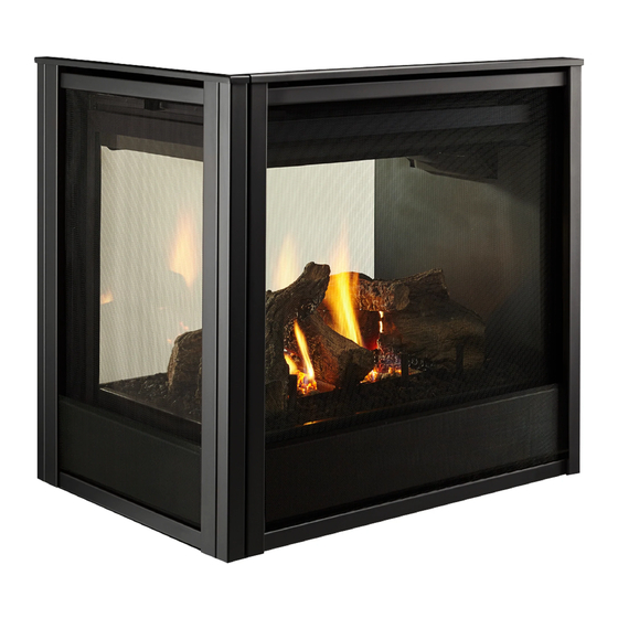
Hearth & Home PIER-DV36IN Installation Manual
Hide thumbs
Also See for PIER-DV36IN:
- Installation instructions (3 pages) ,
- Installation instructions manual (9 pages)
Table of Contents
Advertisement
CAUTION! Risk of Fire! DO NOT store instruction manuals inside fireplace cavity.
High temperatures could cause a fire.
INSTALLER: Leave this manual with the appliance, not inside the appliance.
CONSUMER: Retain this manual for future reference. Do not store inside the appliance.
NOTICE: DO NOT discard this manual!
Models:
This appliance may be installed as an OEM
installation in manufactured home (USA
only) or mobile home and must be installed
in accordance with the manufacturer's
instructions and the Manufactured Home
Construction and Safety Standard, Title 24
CFR, Part 3280 in the United States, or the
Standard for Installation in Mobile Homes,
CAN/CSA Z240 MH Series, in Canada.
This appliance is only for use with the type(s)
of gas indicated on the rating plate. This
appliance is not convertible for use with other
gases, unless a certified kit is used.
Hearth & Home Technologies • PIER-DV36IN, ST-DV36IN Installation Manual • 2658-980 Rev. C • 4/22
Installation Manual
Installation and Appliance Setup
WARNING:
FIRE OR EXPLOSION HAZARD
Failure to follow safety warnings exactly
could result in serious injury, death, or
property damage.
• DO NOT store or use gasoline or other flam-
mable vapors and liquids in the vicinity of this
or any other appliance.
• What to do if you smell gas
- DO NOT try to light any appliance.
- DO NOT touch any electrical switch. DO
NOT use any phone in your building.
- Leave the building immediately.
- Immediately call your gas supplier from
a neighbor's phone. Follow the gas sup-
plier's instructions.
- If you cannot reach your gas supplier, call
the fire department.
• Installation and service must be performed
by a qualified installer, service agency, or the
gas supplier.
DANGER
DO NOT TOUCH GLASS
NEVER ALLOW CHILDREN
A barrier designed to reduce the risk of
burns from the hot viewing glass is provided
with this appliance and must be installed for
the protection of children and other at-risk
individuals.
Decorative barrier front must be ordered separately at
time of appliance purchase. See Section 3.B.
HOT GLASS WILL
CAUSE BURNS.
UNTIL COOLED.
TO TOUCH GLASS.
1
Advertisement
Table of Contents

Related Manuals for Hearth & Home PIER-DV36IN


Summary of Contents for Hearth & Home PIER-DV36IN
- Page 1 Decorative barrier front must be ordered separately at appliance is not convertible for use with other time of appliance purchase. See Section 3.B. gases, unless a certified kit is used. Hearth & Home Technologies • PIER-DV36IN, ST-DV36IN Installation Manual • 2658-980 Rev. C • 4/22...
-
Page 2: Table Of Contents
B. Securing and Leveling the Appliance ....40 C. Non-Combustible Material (Factory-Installed) ..41 = Contains updated information. Hearth & Home Technologies • PIER-DV36IN, ST-DV36IN Installation Manual • 2658-980 Rev. C • 4/22... -
Page 3: Installation Standard Work Checklist
_____________________________________________________________________________________ _________________________________________________________________________________________________ Comments Communicated to party responsible ____________________ by ______________________on ___________ (Builder / Gen. Contractor/) (Installer) (Date) = Contains updated information. 2658-982 3/22 Hearth & Home Technologies • PIER-DV36IN, ST-DV36IN Installation Manual • 2658-980 Rev. C • 4/22... -
Page 4: Product Specific And Important Safety Information
Some local building codes require the use of tempered glass with permanent marking in such locations. Glass meeting this requirement is available from the factory. Please contact your dealer or distributor to order. Hearth & Home Technologies • PIER-DV36IN, ST-DV36IN Installation Manual • 2658-980 Rev. C • 4/22... -
Page 5: Non-Combustible Materials Specification
State of California to cause cancer and reproductive harm. For more information go to: www. P65Warnings.ca.gov. Hearth & Home Technologies • PIER-DV36IN, ST-DV36IN Installation Manual • 2658-980 Rev. C • 4/22... -
Page 6: Requirements For The Commonwealth Of Massachusetts
VENT DIRECTLY BELOW. KEEP CLEAR OF ALL OB- of the installation. STRUCTIONS”. See Gas Connection section for additional Common- wealth of Massachusetts requirements. Hearth & Home Technologies • PIER-DV36IN, ST-DV36IN Installation Manual • 2658-980 Rev. C • 4/22... -
Page 7: Getting Started
Improper installation, adjustment, alteration, service or maintenance can cause injury or property damage. For assistance or additional information, consult a qualified service technician, service agency or your dealer. Hearth & Home Technologies • PIER-DV36IN, ST-DV36IN Installation Manual • 2658-980 Rev. C • 4/22... - Page 8 Increase “A” dimension. b. Increase “C” dimension, however, increasing “B” dimension beyond maximum recommended typically results in higher temperatures. Figure 2.2 Good Faith TV Guidelines Hearth & Home Technologies • PIER-DV36IN, ST-DV36IN Installation Manual • 2658-980 Rev. C • 4/22...
-
Page 9: Tools And Supplies Needed
• Improper positioning of the logs/media (as applicable) or the glass assembly. • Installation and/or use of any component part not approved by Hearth & Home Technologies. Hearth & Home Technologies • PIER-DV36IN, ST-DV36IN Installation Manual • 2658-980 Rev. C • 4/22... -
Page 10: Framing And Clearances
LEFT VIEW Location Inches Millimeters Location Inches Millimeters 1-1/2 42-1/2 1080 24-1/2 33-1/2 9-1/2 2-1/8 34-5/8 4-1/8 4-1/4 38-1/8 Figure 3.1 Appliance Dimensions - ST-DV36IN Hearth & Home Technologies • PIER-DV36IN, ST-DV36IN Installation Manual • 2658-980 Rev. C • 4/22... - Page 11 LEFT VIEW Location Inches Millimeters Location Inches Millimeters 1-1/2 37-1/8 40-1/2 1029 24-1/2 33-1/2 9-1/2 2-1/8 34-5/8 4-1/8 4-1/4 38-1/8 Figure 3.2 Appliance Dimensions - PIER-DV36IN Hearth & Home Technologies • PIER-DV36IN, ST-DV36IN Installation Manual • 2658-980 Rev. C • 4/22...
-
Page 12: Decorative Barrier Front Dimension Diagrams
6-7/8 32-1/16 33-7/16 END PANEL MSEP-36-BK (Model: PIER-DV36IN) MSEP-36-BK Location Inches Millimeters 20-1/8 22-11/16 26-11/16 1-3/8 6-7/8 32-1/16 33-7/16 Figure 3.3 Decorative Barrier Front Dimensions Hearth & Home Technologies • PIER-DV36IN, ST-DV36IN Installation Manual • 2658-980 Rev. C • 4/22... -
Page 13: Appliance Location And Clearances To Combustibles
36 in. 36 in. 914 mm 914 mm PIER-DV36IN 36 in. 914 mm 36 in. 914 mm ST-DV36IN 36 in. 914 mm Figure 3.4 Appliance Locations Hearth & Home Technologies • PIER-DV36IN, ST-DV36IN Installation Manual • 2658-980 Rev. C • 4/22... - Page 14 Adjust framing dimensions for interior sheathing (such as sheetrock). G* For installations with vinyl flooring, see Section 3.E. Figure 3.5 Clearances to Combustibles - ST-DV36IN Hearth & Home Technologies • PIER-DV36IN, ST-DV36IN Installation Manual • 2658-980 Rev. C • 4/22...
- Page 15 Adjust framing dimensions for interior sheathing (such as sheetrock). G* For installations with vinyl flooring, see Section 3.E. Figure 3.6 Clearances to Combustibles - PIER-DV36IN Hearth & Home Technologies • PIER-DV36IN, ST-DV36IN Installation Manual • 2658-980 Rev. C • 4/22...
- Page 16 FACTORY-INSTALLED NON-COMBUSTIBLE BOARD 3-7/8 in. = AIR SPACE REQUIRED Figure 3.7 Non-Combustible Zone Hearth & Home Technologies • PIER-DV36IN, ST-DV36IN Installation Manual • 2658-980 Rev. C • 4/22...
-
Page 17: Constructing The Appliance Chase
110 °F in a room with ambient temperature of 70 °F. Consult flooring specifications to ensure compatibility. Hearth & Home Technologies • PIER-DV36IN, ST-DV36IN Installation Manual • 2658-980 Rev. C • 4/22... -
Page 18: Termination Location And Vent Information
Over 20/12 to 21/12 ..........8.0 * H minimum may vary depending on regional snowfall. Refer to local codes. Figure 4.1 Minimum Height From Roof to Lowest Discharge Opening Hearth & Home Technologies • PIER-DV36IN, ST-DV36IN Installation Manual • 2658-980 Rev. C • 4/22... - Page 19 Measure horizontal and vertical termination cap clearances as noted in Figure 4.3 and Figure 4.4. H=Measure Horizontal Distances from H V=Measure Vertical Distances from V Figure 4.3 Hearth & Home Technologies • PIER-DV36IN, ST-DV36IN Installation Manual • 2658-980 Rev. C • 4/22...
-
Page 20: Vent Terminal Clearances
12 in. (305 mm)* two sides beneath the floor.) vinyl or composite overhang 42 in. (1067 mm) 42 in. (1067 mm) Figure 4.5 Minimum Clearances for Termination Hearth & Home Technologies • PIER-DV36IN, ST-DV36IN Installation Manual • 2658-980 Rev. C • 4/22... -
Page 21: Use Of Elbows
DVP24 DVP36 25-1/2 DVP48 1219 DVP6A 3 to 6 76 to 152 2-1/8-4-1/4 54-108 DVP12A 3 to 12 76 to 305 2-1/8-8-1/2 54-216 Figure 4.6 Hearth & Home Technologies • PIER-DV36IN, ST-DV36IN Installation Manual • 2658-980 Rev. C • 4/22... -
Page 22: Vent Diagrams
16 ft max. towards total elbow count. (4.87 m) Note: Reference Figure 4.23 for special instructions for use of 45º elbow on rear vent appliances. Figure 4.8 Hearth & Home Technologies • PIER-DV36IN, ST-DV36IN Installation Manual • 2658-980 Rev. C • 4/22... - Page 23 4 ft. SLP DVP-SLP24 Adapter DVP-2SL Figure 4.11 Measure to Top of Last Section of Pipe Figure 4.9 Adapt DVP Pipe to SLP Using DVP-SLP24 & DVP-2SL Hearth & Home Technologies • PIER-DV36IN, ST-DV36IN Installation Manual • 2658-980 Rev. C • 4/22...
- Page 24 4.6 m 6 ft. 1.8 m 18 ft. 5.5 m = 50 ft. (15.2 m) Maximum = 18 ft. (5.5 m) Maximum INSTALLED HORIZONTALLY Figure 4.13 Hearth & Home Technologies • PIER-DV36IN, ST-DV36IN Installation Manual • 2658-980 Rev. C • 4/22...
- Page 25 3 ft. 914 mm 12 ft.* 3.7 m 6 ft 1.8 m = 18 ft. (5.5 m) Maximum = 50 ft. (15.2 m) Maximum Figure 4.14 Hearth & Home Technologies • PIER-DV36IN, ST-DV36IN Installation Manual • 2658-980 Rev. C • 4/22...
- Page 26 6 ft. 1.8 m 6 ft. 1.8 m = 50 ft. (15.2 m) Maximum = 18 ft. (5.5 m) Maximum Installed Vertically Installed Horizontally Figure 4.15 Hearth & Home Technologies • PIER-DV36IN, ST-DV36IN Installation Manual • 2658-980 Rev. C • 4/22...
- Page 27 10-60 feet, an exhaust restrictor may restrictor installation. be needed. The exhaust restrictor can be located in the appliance manual bag. Figure 4.17 Hearth & Home Technologies • PIER-DV36IN, ST-DV36IN Installation Manual • 2658-980 Rev. C • 4/22...
- Page 28 MUST subtract one number from the table above. Example: Top vent 60 ft vertical with DVP pipe = 3-3 Top vent 60 ft vertical with SLP pipe = 2-2 Hearth & Home Technologies • PIER-DV36IN, ST-DV36IN Installation Manual • 2658-980 Rev. C • 4/22...
- Page 29 18 ft. 5.5 m = 50 ft (15.2 m) Maximum *No specific restrictions on this value EXCEPT cannot exceed 50 ft (15.2 m) Figure 4.20 Hearth & Home Technologies • PIER-DV36IN, ST-DV36IN Installation Manual • 2658-980 Rev. C • 4/22...
- Page 30 5.5 m = 18 ft (5.5 m) Maximum *No specific restrictions on this value EXCEPT cannot exceed 50 ft (15.2 m) INSTALLED HORIZONTALLY Figure 4.21 Hearth & Home Technologies • PIER-DV36IN, ST-DV36IN Installation Manual • 2658-980 Rev. C • 4/22...
- Page 31 = 16 in. (406 mm) Maximum No Elbow Figure 4.22 One 45º Elbow DO NOT use a 45º elbow in corner installations. Use two 90º elbow instead. Figure 4.23 Hearth & Home Technologies • PIER-DV36IN, ST-DV36IN Installation Manual • 2658-980 Rev. C • 4/22...
- Page 32 1.2 m 8 ft. 2.4 m = 40 ft (12.2 m) Maximum = 3 ft (94 mm) Maximum = 12 ft (3.7 m) Maximum Figure 4.25 Hearth & Home Technologies • PIER-DV36IN, ST-DV36IN Installation Manual • 2658-980 Rev. C • 4/22...
- Page 33 10 ft. 6 ft. 1.8 m 12 ft. 3.7 m = 50 ft (15.2 m) Maximum = 16 ft (4.9 m) Maximum INSTALLED HORIZONTALLY Figure 4.27 Hearth & Home Technologies • PIER-DV36IN, ST-DV36IN Installation Manual • 2658-980 Rev. C • 4/22...
- Page 34 1.8 m *No specific restrictions on this value EXCEPT cannot exceed 50 ft. (15.2 m) Maximum = 6 ft. (1.8 m) Maximum INSTALLED HORIZONTALLY Figure 4.29 Hearth & Home Technologies • PIER-DV36IN, ST-DV36IN Installation Manual • 2658-980 Rev. C • 4/22...
-
Page 35: Vent Clearances And Vent Framing
Top: 2-1/2 in. (64 mm) Bottom: 1/2 in. (13 mm) Sides: 1 in. (25 mm) Figure 5.1 Horizontal Venting Clearances To Combustible Materials Hearth & Home Technologies • PIER-DV36IN, ST-DV36IN Installation Manual • 2658-980 Rev. C • 4/22... -
Page 36: Wall Penetration Framing/Firestops
Note: Center of the horizontal vent pipe to the vertical measuring surface of a trap cap is 5 inches (127 mm). Figure 5.3 Wall Penetration Hearth & Home Technologies • PIER-DV36IN, ST-DV36IN Installation Manual • 2658-980 Rev. C • 4/22... -
Page 37: Ceiling Firestop/Floor Penetration Framing
INSTALL ATTIC INSULATION SHIELDS BEFORE OR AFTER INSTALLATION OF VENT SYSTEM CEILING FIRESTOP CEILING FIRESTOP INSTALLED BELOW CEILING INSTALLED ABOVE CEILING Figure 5.5 Installing the Attic Shield Hearth & Home Technologies • PIER-DV36IN, ST-DV36IN Installation Manual • 2658-980 Rev. C • 4/22... -
Page 38: Appliance Preparation
Secure the vent gasket to the appliance with two self-tapping screws found in the manual bag. Note: The vent gasket can found in the manual bag. Proceed to Section 6.B. Hearth & Home Technologies • PIER-DV36IN, ST-DV36IN Installation Manual • 2658-980 Rev. C • 4/22... - Page 39 Secure the vent gasket to the appliance with two self-tapping screws found in the manual bag. Note: The vent gasket can found in the manual bag. Hearth & Home Technologies • PIER-DV36IN, ST-DV36IN Installation Manual • 2658-980 Rev. C • 4/22...
-
Page 40: Securing And Leveling The Appliance
• Optional: Secure the appliance to the floor by inserting two screws through the pilot holes at the bottom of the appliance. NAILING TABS Figure 6.11 Securing An Appliance Hearth & Home Technologies • PIER-DV36IN, ST-DV36IN Installation Manual • 2658-980 Rev. C • 4/22... -
Page 41: Non-Combustible Material (Factory-Installed)
This board must be used. Do not remove. See Figure 6.13. NON-COMBUSTIBLE BOARD NON-COMBUSTIBLE BOARD Figure 6.13 Non-combustible Board Hearth & Home Technologies • PIER-DV36IN, ST-DV36IN Installation Manual • 2658-980 Rev. C • 4/22... -
Page 42: Venting
• Only outer pipes need to be sealed. All unit collar, pipe, slip section, elbow and cap outer flues shall be sealed in this manner, unless otherwise stated. Hearth & Home Technologies • PIER-DV36IN, ST-DV36IN Installation Manual • 2658-980 Rev. C • 4/22... - Page 43 Figure 7.1 High Temperature Silicone Sealant Lances Lances Figure 7.3 Figure 7.2 Note: Make sure that the seams are not aligned to prevent unintentional disconnection. CORRECT INCORRECT Figure 7.4 Seams Hearth & Home Technologies • PIER-DV36IN, ST-DV36IN Installation Manual • 2658-980 Rev. C • 4/22...
-
Page 44: Assemble Vent Sections (Slp Only)
• Only outer pipes need to be sealed. All unit collar, pipe, slip section, elbow and cap outer flues shall be sealed in this manner, unless otherwise stated. Hearth & Home Technologies • PIER-DV36IN, ST-DV36IN Installation Manual • 2658-980 Rev. C • 4/22... -
Page 45: Assemble Slip Sections
“Assembling Pipe Sections.” NOTICE: If slip section is too long, the inner and outer flues of the slip section can be cut to the desired length. Hearth & Home Technologies • PIER-DV36IN, ST-DV36IN Installation Manual • 2658-980 Rev. C • 4/22... -
Page 46: Secure The Vent Sections
• SLP ceiling firestops have tabs that may be used to provide vertical support. 120º Figure 7.11 Align and Disassemble Vent Sections Figure 7.8 Securing Vertical Pipe Sections 120º Figure 7.9 Securing Horizontal Pipe Sections Hearth & Home Technologies • PIER-DV36IN, ST-DV36IN Installation Manual • 2658-980 Rev. C • 4/22... -
Page 47: Vertical Termination Requirements
• Tighten nut and make sure the collar is tight against the pipe section. • Seal around the top of the storm collar. See Figure 7.14. SEAL Figure 7.12 Figure 7.12 Hearth & Home Technologies • PIER-DV36IN, ST-DV36IN Installation Manual • 2658-980 Rev. C • 4/22... -
Page 48: Horizontal Termination Requirements
• Rest the small leg on the extended heat shield on top of the pipe section to properly space it from the pipe section. Important Notice: Heat shields may not be field constructed. Hearth & Home Technologies • PIER-DV36IN, ST-DV36IN Installation Manual • 2658-980 Rev. C • 4/22... - Page 49 HRC caps are available. When penetrating a brick wall, a brick extension kit is available for framing the brick. Hearth & Home Technologies • PIER-DV36IN, ST-DV36IN Installation Manual • 2658-980 Rev. C • 4/22...
-
Page 50: Electrical Information
If interference is occurring on the same circuit, the use of surge protectors may help alleviate the interference. ROMEX CONNECTORS Figure 8.1 Junction Box Detail Hearth & Home Technologies • PIER-DV36IN, ST-DV36IN Installation Manual • 2658-980 Rev. C • 4/22... -
Page 51: Wiring Requirements
Do not store batteries in the battery pack when the appliance is powered by the 6 volt transformer connected to permanent electrical service. Hearth & Home Technologies • PIER-DV36IN, ST-DV36IN Installation Manual • 2658-980 Rev. C • 4/22... - Page 52 RF MODULE ORANGE 2326-120 GROUND TO FIREPLACE CHASSIS GREEN IFT-RC150 WIRELESS WALL SWITCH WHITE WIRE ASSEMBLY 2118-170 Figure 8.2 IntelliFire Touch Wiring With Wall Switch Hearth & Home Technologies • PIER-DV36IN, ST-DV36IN Installation Manual • 2658-980 Rev. C • 4/22...
- Page 53 PVI-WH20 PVI-WH40 PVI-WH60 ORANGE PVI-WH80 PVI-WH100 GROUND TO FIREPLACE CHASSIS PVI-SLP-B OR PVLP-SLP GREEN PVLP-SLP PVI-SLP-B Figure 8.3 IntelliFire Touch Wiring With Optional Power Vent Hearth & Home Technologies • PIER-DV36IN, ST-DV36IN Installation Manual • 2658-980 Rev. C • 4/22...
-
Page 54: Fan (Optional)
Figure 8.5. RHEOSTAT JUNCTION BOX SWITCH TEMPERATURE SENSOR BLUE Figure 8.5 Detail of Fan Wiring with Rheostat Hearth & Home Technologies • PIER-DV36IN, ST-DV36IN Installation Manual • 2658-980 Rev. C • 4/22... -
Page 55: Gas Information
Check with your local gas utility to determine proper mm) control valve inlet. orifice size. • If substituting for these components, please consult local codes for compliance. Hearth & Home Technologies • PIER-DV36IN, ST-DV36IN Installation Manual • 2658-980 Rev. C • 4/22... -
Page 56: Air Shutter Setting
Note: All vent runs may need to be evaluated for ideal shutter settings. Shutter distances may vary due to vent run, fuel quality, and elevation. Hearth & Home Technologies • PIER-DV36IN, ST-DV36IN Installation Manual • 2658-980 Rev. C • 4/22... -
Page 57: Finishing
0 in. 0 in. High Temperature Sealant (300° F/149° C min.) Top and Side Seal Joint = Factory-Installed Non-Combustible Board Figure 10.1 Non-combustible Facing Diagram Hearth & Home Technologies • PIER-DV36IN, ST-DV36IN Installation Manual • 2658-980 Rev. C • 4/22... -
Page 58: Installing A Television
MIN. 2-1/2 MEASUREMENT FROM FIREPLACE OPENING TO BOTTOM OF APPLIANCE= 33-1/2 IN. Figure 10.4 Minimum Vertical and Maximum Horizontal Dimensions of Combustibles Hearth & Home Technologies • PIER-DV36IN, ST-DV36IN Installation Manual • 2658-980 Rev. C • 4/22... - Page 59 Figure 10.8 Non-Combustible Mantel Leg OPENING TO BOTTOM OF (Acceptable on both sides of opening) APPLIANCE= 33-1/2 IN. Figure 10.6 Minimum Vertical and Maximum Horizontal Dimensions of Non-Combustibles Hearth & Home Technologies • PIER-DV36IN, ST-DV36IN Installation Manual • 2658-980 Rev. C • 4/22...
-
Page 60: Decorative Barrier Front Dimensions For Finishing
Stop finishing material flush with opening. Figure 10.9 MSFR-36-BK Decorative Barrier Front Finish up to the appliance opening for best results. Figure 10.10 PIER-DV36IN Decorative Barrier Front Finishing Hearth & Home Technologies • PIER-DV36IN, ST-DV36IN Installation Manual • 2658-980 Rev. C • 4/22... -
Page 61: Appliance Setup
For instructions on removing and replacing the fixed glass assembly, see Section 11.F. B. Clean the Appliance Clean/vacuum any sawdust that may have accumulated inside the firebox or underneath in the control cavity. Hearth & Home Technologies • PIER-DV36IN, ST-DV36IN Installation Manual • 2658-980 Rev. C • 4/22... -
Page 62: Glowing Ember And Lava Rock Placement
The embers provided should be enough for 3 to 5 applications. DO NOT PLACE EMBERS IN THE CIRCLED AREAS PILOT LOCATED HERE Figure 11.1 Ember Placement Hearth & Home Technologies • PIER-DV36IN, ST-DV36IN Installation Manual • 2658-980 Rev. C • 4/22... -
Page 63: Install The Log Assembly
Mate the notch on the end of log # 1 with the hump on top of log A. Set the other end of Log #1 onto the smooth area on top of Log C. Hearth & Home Technologies • PIER-DV36IN, ST-DV36IN Installation Manual • 2658-980 Rev. C • 4/22... - Page 64 The bottom end of log #3 should come in contact with the far left grate tine. Mate the bottom of log # 3 with the indentations on Log D and the top of Log #2. 2128-935C Hearth & Home Technologies • PIER-DV36IN, ST-DV36IN Installation Manual • 2658-980 Rev. C • 4/22...
-
Page 65: Intellifire Touch ® Control System Setup
2. Follow the installation instructions provided with the IntelliFire Touch remote and/or accessory kit(s). LATCHES (BOTH BOTTOM AND TOP) GLASS ASSEMBLY Figure 11.4 Fixed Glass Assembly Hearth & Home Technologies • PIER-DV36IN, ST-DV36IN Installation Manual • 2658-980 Rev. C • 4/22... -
Page 66: Install Decorative Barrier Front
For more information refer to the instructions supplied with your decorative barrier front. Hearth & Home Technologies • PIER-DV36IN, ST-DV36IN Installation Manual • 2658-980 Rev. C • 4/22... -
Page 67: Reference Materials
6 in. 14 IN. (152 mm) (356 MM) 12 IN. (305 MM) DVP-WS (Wall Shield Firestop) DVP-RDS ROOF DECK INSULATION SHIELD Figure 12.1 DVP Vent Components Hearth & Home Technologies • PIER-DV36IN, ST-DV36IN Installation Manual • 2658-980 Rev. C • 4/22... - Page 68 DVP-TRAP2 DVP-TRAP1 DVP-TRAPK2 DVP-TRAPK1 DVP-HPC2 DVP-HPC1 Can adjust 4-1/8 in. (6-3/8 to 10-1/2) Can adjust 2-1/8 in. (4-1/4 to 6-3/8) Figure 12.2 DVP Vent Components Hearth & Home Technologies • PIER-DV36IN, ST-DV36IN Installation Manual • 2658-980 Rev. C • 4/22...
- Page 69 9-1/2 in. (352 mm) (241 mm) 26 in. 660 mm 14 in. (356 mm) DVP-HSM-B DRC-RADIUS Cap Shield Extended Heat Shield Figure 12.3 DVP Vent Components Hearth & Home Technologies • PIER-DV36IN, ST-DV36IN Installation Manual • 2658-980 Rev. C • 4/22...
- Page 70 (314 mm) DTO134 8-3/4 in. (222 mm) DTO146 DTS134 1-5/8 in. DTS146 (41 mm) LDS33 LDS46 DVP-HPC High Performance Cap LDS-BV Figure 12.4 DVP Vent Components Hearth & Home Technologies • PIER-DV36IN, ST-DV36IN Installation Manual • 2658-980 Rev. C • 4/22...
- Page 71 Option B: IFT-RC150, IFT-ACM, IFT-WFM and an IntelliFire App that can be downloaded from the app store. These accessories are purchased separately from the PVV-SLP. Contact your dealer to order. Figure 12.5 PVV-SLP Vent Components Hearth & Home Technologies • PIER-DV36IN, ST-DV36IN Installation Manual • 2658-980 Rev. C • 4/22...
- Page 72 (346 mm) 424 mm (424 mm) 12-1/2 IN. (318 mm) SLP-LPC SLP Low Profile Cap (Approved for use with PVI-SLP-B only) Figure 12.6 PVI-SLP-B Vent Components Hearth & Home Technologies • PIER-DV36IN, ST-DV36IN Installation Manual • 2658-980 Rev. C • 4/22...
- Page 73 60 FT PV Wire Harness PVI-WH60 80 FT PV Wire Harness PVI-WH80 100 FT PV Wire Harness PVI-WH100 PVLP-HS PVLP-BEK Heat Shield Brick Kit Figure 12.7 PVLP-SLP Vent Components Hearth & Home Technologies • PIER-DV36IN, ST-DV36IN Installation Manual • 2658-980 Rev. C • 4/22...
- Page 74 12 in. 5-1/2 in. 220 mm 38 mm 305 mm 146 mm SLP-WS SLP-FS Wall Shield Firestop Ceiling Firestop Figure 12.8 SLP Series Vent Components Hearth & Home Technologies • PIER-DV36IN, ST-DV36IN Installation Manual • 2658-980 Rev. C • 4/22...
- Page 75 12-5/8 IN. 10-5/8 IN. 59 mm 367 mm (321 mm) (270 mm) SLP-RDS SLP-WT-BK ROOF DECK INSULATION SHIELD Wall Thimble-Black Figure 12.9 SLP Series Vent Components Hearth & Home Technologies • PIER-DV36IN, ST-DV36IN Installation Manual • 2658-980 Rev. C • 4/22...
- Page 76 28-1/2 in. 4-1/8 in. 724 mm 105 mm 13-1/2 in. 4-3/4 in. 343 mm 121 mm SLK-SNKD Snorkel Termination Cap Figure 12.10 SLP Series Vent Components Hearth & Home Technologies • PIER-DV36IN, ST-DV36IN Installation Manual • 2658-980 Rev. C • 4/22...
- Page 77 A. Vent Components Diagrams (continued) 8 IN. (203 mm) 15 IN. (381 mm) 12 IN. (305 mm) SLP-HHW2 Horizontal High Wind Termination Cap Figure 12.11 SLP series Vent Components Hearth & Home Technologies • PIER-DV36IN, ST-DV36IN Installation Manual • 2658-980 Rev. C • 4/22...
-
Page 78: Accessories
Please contact your Hearth & Home Technologies dealer with any questions or concerns. For the location of your nearest Hearth & Home Technologies dealer, please visit www.hearthnhome.com. Printed in U.S.A. - Copyright 2022 Hearth & Home Technologies • PIER-DV36IN, ST-DV36IN Installation Manual • 2658-980 Rev. C • 4/22...
Need help?
Do you have a question about the PIER-DV36IN and is the answer not in the manual?
Questions and answers