Table of Contents
Advertisement
Quick Links
www.ti.com
User's Guide
DAC53701EVM
This user's guide describes the characteristics, operation, and use of the DAC53701EVM evaluation module
(EVM). This EVM is designed to evaluate the performance of the
buffered voltage output DACs in a variety of configurations. This EVM is also designed to evaluate the
automotive version devices,
board, evaluation module, and EVM are synonymous with the DAC53701EVM. This document includes a
schematic, reference printed-circuit board (PCB) layouts, and a complete bill of materials.
SLAU841 – OCTOBER 2020
Submit Document Feedback
ABSTRACT
DAC53701-Q1
and DAC43701-Q1. Throughout this document, the terms evaluation
Copyright © 2020 Texas Instruments Incorporated
DAC53701
and
DAC43701
commercial,
DAC53701EVM
1
Advertisement
Table of Contents

Related Manuals for Texas Instruments DAC53701EVM


Summary of Contents for Texas Instruments DAC53701EVM
- Page 1 User’s Guide DAC53701EVM ABSTRACT This user’s guide describes the characteristics, operation, and use of the DAC53701EVM evaluation module (EVM). This EVM is designed to evaluate the performance of the DAC53701 DAC43701 commercial, buffered voltage output DACs in a variety of configurations. This EVM is also designed to evaluate the...
-
Page 2: Table Of Contents
Figure 2-5. Hardware Setup................................ Figure 2-6. Hardware Setup Guidelines............................Figure 3-1. BOOSTXL-DAC-PORT Hardware Block Diagram.....................9 Figure 3-2. DAC53701EVM Hardware Block Diagram......................Figure 3-3. DAC53701EVM GUI Location..........................Figure 3-4. DAC53701EVM GUI Connection Detection......................Figure 3-5. Software Home Page.............................. Figure 3-6. Setup Page................................16... - Page 3 Trademarks List of Tables Table 1-1. Contents of DAC53701EVM Kit..........................Table 1-2. Required Components Not Included With Kit......................Table 1-3. Related Documentation.............................. Table 2-1. DAC53701EVM Power Supply Inputs.........................7 Table 2-2. BOOSTXL-DAC-PORT Jumper Settings........................Table 3-1. BOOSTXL-DAC-PORT J13 Pin Definitions......................
-
Page 4: Overview
The following document provides information regarding Texas Instruments integrated circuits used in the assembly of the DAC53701EVM. This user's guide is available from the TI web site under literature number SLAU841. Any letter appended to the literature number corresponds to the document revision that is current at the time of the writing of this document. -
Page 5: System Setup
GUI Composer Gallery. Search for DAC53701EVM in the GUI Composer Gallery. Use the down arrow symbol to download the software. There are two downloads: DAC53701EVM GUI and GUI Composer Runtime. Either download both, or just download the EVM GUI; the runtime file can be downloaded through the EVM GUI during installation. The software can also be run online by clicking;... -
Page 6: Figure 2-3. Msp-Exp432E401Y Launchpad (Ti Launchpad )
Figure 2-4. TI Cloud Agent Installation 6. Press the Refresh or Finish button after the installation is complete. This action should detect the Launchpad. 7. Press Start and browse for <Download Directory>\DAC53701EVM_1.0.1_installer_win \install_image_DAC53701EVM.\DAC53701EVM\firmware\acctrl.0.3.0.3b.bin. Press Load Image followed by Verify Image. DAC53701EVM SLAU841 –... -
Page 7: Hardware Setup
C pullups. The IO ports of the Analog EVM Controller and level translators used on the BOOSTXL-DAC-PORT and DAC53701EVM can withstand a maximum of 3.6-V IO levels. The TI Launchpad also generates digital signals used to communicate with the EVM board. -
Page 8: Figure 2-6. Hardware Setup Guidelines
Figure 2-6. Hardware Setup Guidelines 2.2.3 Electrostatic Discharge Warning Many of the components on the DAC53701EVM are susceptible to damage by electrostatic discharge (ESD). Observe proper ESD handling precautions when unpacking and handling the EVM, including the use of a grounded wrist strap at an approved ESD workstation. -
Page 9: Detailed Description
Figure 3-1. BOOSTXL-DAC-PORT Hardware Block Diagram 3.1.1.1 Signal Definition of the BOOSTXL-DAC-PORT The BOOSTXL-DAC-PORT provides hardware connectors for the TI Launchpad (J13, J14), external power (J12), the DAC53701EVM (J1, J2), and the external function extender (J4, J5). The descriptions are provided in Table 3-1 through Table 3-5. -
Page 10: Table 3-1. Boostxl-Dac-Port J13 Pin Definitions
General-purpose I/O GPIO General-purpose I/O VDD_SENSE Sense Input for VDD VIO_SENSE Sense Input for VIO GPIO General-purpose I/O GPIO General-purpose I/O GPIO General-purpose I/O GPIO General-purpose I/O DAC53701EVM SLAU841 – OCTOBER 2020 Submit Document Feedback Copyright © 2020 Texas Instruments Incorporated... -
Page 11: Table 3-3. Boostxl-Dac-Port J4 Pin Definitions
VIO or DAC_VIO Output Table 3-5. BOOSTXL-DAC-PORT J12 Pin Definitions Pin# Signal Description High-voltage positive power supply High-voltage negative power supply Ground EXT_VDD External VDD EXT_VIO External VIO SLAU841 – OCTOBER 2020 DAC53701EVM Submit Document Feedback Copyright © 2020 Texas Instruments Incorporated... -
Page 12: Figure 3-2. Dac53701Evm Hardware Block Diagram
Detailed Description www.ti.com 3.1.2 Theory of Operation for the DAC53701EVM Hardware The block diagram of the DAC53701EVM board is displayed in Figure 3-2. The EVM board connects to BOOSTXL-DAC-PORT with two 16-pin connectors. These headers provide access to all DAC pins. The EVM board also houses EEPROM and an I C buffer. -
Page 13: Table 3-6. Dac53701Evm J2 Pin Definitions
Detailed Description 3.1.2.1 Signal Definition of the DAC53701EVM The DAC53701EVM provides access to all DAC pins through connection J1 and J2, as listed in Table 3-6 Table 3-7. Table 3-6. DAC53701EVM J2 Pin Definitions Pin# Signal Description VDD power supply... -
Page 14: Software Description
The software provides basic control of all the registers and functions to the DAC53701 device. 3.2.1 Starting the Software To launch the software, locate the Texas Instruments folder in the All Programs menu, and select the DAC53701 EVM icon. Figure 3-3. DAC53701EVM GUI Location... -
Page 15: Figure 3-5. Software Home Page
Detailed Description 3.2.2 Software Features The DAC53701EVM incorporates interactive functions that help configure the DAC53701 device. These functions are built into several GUI pages, as shown in the following subsections. The Menu allows the user to switch between pages, with each page representing a feature of the software. -
Page 16: Figure 3-6. Setup Page
Figure 3-6, guides the user to perform a one-time firmware upgrade for the TI Launchpad, and details how the TI Launchpad, BOOSTXL-DAC-PORT, and DAC53701EVM are stacked. This page also shows the default jumper settings for the BOOSTXL-DAC-PORT. Figure 3-6. Setup Page DAC53701EVM SLAU841 –... -
Page 17: Figure 3-7. Dac Quick-Start Page: Basic Dac Tab
The GPI pin programming has not been provided in this version of the software, although the EVM hardware has options for providing signals to DAC53701 through header J2 SLAU841 – OCTOBER 2020 DAC53701EVM Submit Document Feedback Copyright © 2020 Texas Instruments Incorporated... -
Page 18: Figure 3-8. Dac Quick-Start Page: Margining Tab
The register settings are programmed or retrieved using the EEPROM PROGRAM or RELOAD buttons, respectively. The trigger bits are not loaded to the EEPROM because they are edge sensitive. DAC53701EVM SLAU841 – OCTOBER 2020 Submit Document Feedback Copyright © 2020 Texas Instruments Incorporated... -
Page 19: Figure 3-9. Dac Quick Start Page: Function Generation
Any change to the function settings can only be done when the function is off. The register settings can be programmed or retrieved using the EEPROM PROGRAM or RELOAD buttons, respectively. SLAU841 – OCTOBER 2020 DAC53701EVM Submit Document Feedback Copyright © 2020 Texas Instruments Incorporated... -
Page 20: Figure 3-10. Dac Quick-Start Page: Alarms Tab
The radio buttons are used to trigger any one of the alarms. The register settings are programmed or retrieved using the EEPROM PROGRAM or RELOAD buttons, respectively. DAC53701EVM SLAU841 – OCTOBER 2020 Submit Document Feedback Copyright © 2020 Texas Instruments Incorporated... -
Page 21: Figure 3-11. Register Map Page
Detailed Description 3.2.2.4 Register Map Page The DAC53701EVM Register Map page, as shown in Figure 3-11, allows the user to access low level communication directly with the DAC53701 registers. Selecting a register on the Register Map list shows a description of the values in that register, as well as information on the register address, default value, size, and current value. -
Page 22: Schematic, Pcb Layout, And Bill Of Materials
Figure 3-13. Collateral Page 4 Schematic, PCB Layout, and Bill of Materials This section contains the complete bill of materials and schematic diagram for the BOOSTXL-DAC-PORT and DAC53701EVM. DAC53701EVM SLAU841 – OCTOBER 2020 Submit Document Feedback Copyright © 2020 Texas Instruments Incorporated... -
Page 23: Boostxl-Dac-Port Schematic
This assumes that the BO board has another buffer (VCC-VSS)-max = 43V to isolate the EEPROM signals from the DAC unless DAC_VIO is present VIO Selection Figure 4-1. BOOSTXL-DAC-PORT Schematic Page 1 SLAU841 – OCTOBER 2020 DAC53701EVM Submit Document Feedback Copyright © 2020 Texas Instruments Incorporated... -
Page 24: Figure 4-2. Boostxl-Dac-Port Schematic
VDD can either be used directly 1.0k sides similar to LP connectors or through an optional voltage divider 0.1uF Figure 4-2. BOOSTXL-DAC-PORT Schematic Page 2 DAC53701EVM SLAU841 – OCTOBER 2020 Submit Document Feedback Copyright © 2020 Texas Instruments Incorporated... -
Page 25: Dac53701Evm Schematic
B side of the buffer 10.0k TCA9800DGKR 10.0k 10.0k 10.0k 10.0k BR24G32FVT-3AGE2 0.1uF This buffer is disabled by default due to absense of VIO DAC_SDA DAC_SCL Figure 4-3. DAC53701EVM Schematic SLAU841 – OCTOBER 2020 DAC53701EVM Submit Document Feedback Copyright © 2020 Texas Instruments Incorporated... -
Page 26: Pcb Components Layout
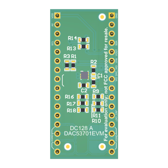
Schematic, PCB Layout, and Bill of Materials www.ti.com 4.3 PCB Components Layout Figure 4-4 through Figure 4-8 show the layout of the components for the DAC53701EVM board. Figure 4-4. BOOSTXL-DAC-PORT PCB Components Layout Figure 4-5. BOOSTXL-DAC-PORT Top Layer DAC53701EVM SLAU841 – OCTOBER 2020 Submit Document Feedback... -
Page 27: Figure 4-6. Boostxl-Dac-Port Bottom Layer
Schematic, PCB Layout, and Bill of Materials Figure 4-6. BOOSTXL-DAC-PORT Bottom Layer Figure 4-7. DAC53701EVM PCB Components Layout SLAU841 – OCTOBER 2020 DAC53701EVM Submit Document Feedback Copyright © 2020 Texas Instruments Incorporated... -
Page 28: Figure 4-8. Dac53701Evm Layers
Schematic, PCB Layout, and Bill of Materials www.ti.com Figure 4-8. DAC53701EVM Layers DAC53701EVM SLAU841 – OCTOBER 2020 Submit Document Feedback Copyright © 2020 Texas Instruments Incorporated... -
Page 29: Boostxl-Dac-Port Bill Of Materials
RES, 1.0 k, 5%, 0.1 W, AEC- 0603 CRCW06031K00JNEA Vishay-Dale Q200 Grade 0, 0603 R8, R10 4.99k RES, 4.99 k, 1%, 0.1 W, 0603 0603 CR0603-FX-4991ELF Bourns SLAU841 – OCTOBER 2020 DAC53701EVM Submit Document Feedback Copyright © 2020 Texas Instruments Incorporated... - Page 30 R15, R16, R38, R43, R46 RES, 0, 5%, 0.1 W, 0603 0603 RC0603JR-070RL Yageo America R40, R44 RES, 33, 5%, 0.1 W, AEC- 0603 CRCW060333R0JNEA Vishay-Dale Q200 Grade 0, 0603 DAC53701EVM SLAU841 – OCTOBER 2020 Submit Document Feedback Copyright © 2020 Texas Instruments Incorporated...
-
Page 31: Dac53701Evm Bill Of Materials
Schematic, PCB Layout, and Bill of Materials 4.5 DAC53701EVM Bill of Materials Table 4-2. DAC53701EVM Bill of Materials Designator Quantity Value Description Package Reference Part Number Manufacturer !PCB Printed Circuit Board DC128 C1, C3, C4, C5 0.1uF CAP, CERM, 0.1 uF, 25 V, +/-... - Page 32 STANDARD TERMS FOR EVALUATION MODULES Delivery: TI delivers TI evaluation boards, kits, or modules, including any accompanying demonstration software, components, and/or documentation which may be provided together or separately (collectively, an “EVM” or “EVMs”) to the User (“User”) in accordance with the terms set forth herein.
- Page 33 www.ti.com Regulatory Notices: 3.1 United States 3.1.1 Notice applicable to EVMs not FCC-Approved: FCC NOTICE: This kit is designed to allow product developers to evaluate electronic components, circuitry, or software associated with the kit to determine whether to incorporate such items in a finished product and software developers to write software applications for use with the end product.
- Page 34 www.ti.com Concernant les EVMs avec antennes détachables Conformément à la réglementation d'Industrie Canada, le présent émetteur radio peut fonctionner avec une antenne d'un type et d'un gain maximal (ou inférieur) approuvé pour l'émetteur par Industrie Canada. Dans le but de réduire les risques de brouillage radioélectrique à...
- Page 35 www.ti.com EVM Use Restrictions and Warnings: 4.1 EVMS ARE NOT FOR USE IN FUNCTIONAL SAFETY AND/OR SAFETY CRITICAL EVALUATIONS, INCLUDING BUT NOT LIMITED TO EVALUATIONS OF LIFE SUPPORT APPLICATIONS. 4.2 User must read and apply the user guide and other available documentation provided by TI regarding the EVM prior to handling or using the EVM, including without limitation any warning or restriction notices.
- Page 36 Notwithstanding the foregoing, any judgment may be enforced in any United States or foreign court, and TI may seek injunctive relief in any United States or foreign court. Mailing Address: Texas Instruments, Post Office Box 655303, Dallas, Texas 75265 Copyright © 2019, Texas Instruments Incorporated...
- Page 37 TI products. TI’s provision of these resources does not expand or otherwise alter TI’s applicable warranties or warranty disclaimers for TI products. Mailing Address: Texas Instruments, Post Office Box 655303, Dallas, Texas 75265 Copyright © 2020, Texas Instruments Incorporated...
- Page 38 Mouser Electronics Authorized Distributor Click to View Pricing, Inventory, Delivery & Lifecycle Information: Texas Instruments DAC53701EVM...
Need help?
Do you have a question about the DAC53701EVM and is the answer not in the manual?
Questions and answers