Table of Contents
Advertisement
Quick Links
This user's guide describes the characteristics, operation, and use of the DAC53401EVM evaluation
module (EVM). This EVM is designed to evaluate the performance of the
output DAC in a variety of configurations. Throughout this document, the terms evaluation board,
evaluation module, and EVM are synonymous with the DAC53401EVM. This document includes a
schematic, reference printed-circuit board (PCB) layouts, and a complete bill of materials.
.....................................................................................................................
1
Overview
2
System Setup
3
Detailed Description
4
Schematic, PCB Layout, and Bill of Materials
SLAU805 – July 2019
Submit Documentation Feedback
................................................................................................................
.........................................................................................................
Copyright © 2019, Texas Instruments Incorporated
Contents
..........................................................................
User's Guide
SLAU805 – July 2019
DAC53401EVM
DAC53401
buffered voltage
DAC53401EVM
3
4
8
22
1
Advertisement
Table of Contents

Related Manuals for Texas Instruments DAC53401EVM


Summary of Contents for Texas Instruments DAC53401EVM
- Page 1 User's Guide SLAU805 – July 2019 DAC53401EVM This user’s guide describes the characteristics, operation, and use of the DAC53401EVM evaluation module (EVM). This EVM is designed to evaluate the performance of the DAC53401 buffered voltage output DAC in a variety of configurations. Throughout this document, the terms evaluation board, evaluation module, and EVM are synonymous with the DAC53401EVM.
-
Page 2: Table Of Contents
DAC53401EVM Bill of Materials Trademarks Windows is a trademark of Microsoft Corporation. PMBus is a trademark of SMIF, Inc. All other trademarks are the property of their respective owners. DAC53401EVM SLAU805 – July 2019 Submit Documentation Feedback Copyright © 2019, Texas Instruments Incorporated... -
Page 3: Contents Of Dac53401Evm Kit
The following document provides information regarding Texas Instruments integrated circuits used in the assembly of the DAC53401EVM. This user's guide is available from the TI web site under literature number SLAU805. Any letter appended to the literature number corresponds to the document revision that is current at the time of the writing of this document. -
Page 4: Dac53401Evm Software Setup
GUI Composer Gallery. Search for DAC53401EVM inn the GUI Composer Gallery. Use the down arrow symbol to download the software. There are two downloads: DAC53401EVM GUI and GUI Composer Runtime. Either download both, or just download the EVM GUI; the runtime can be downloaded through the EVM GUI during installation. -
Page 5: Ti Cloud Agent Installation
7. Press Start and browse for <Download Directory>\DAC53401EVM_1.0.1_installer_win\install_image_DAC53401EVM.\DAC53401EVM\firmwar e\acctrl.0.3.0.3b.bin. Press Load Image followed by Verify Image. Remove Jumper Mount Jumper Figure 4. Analog EVM Controller Setup SLAU805 – July 2019 DAC53401EVM Submit Documentation Feedback Copyright © 2019, Texas Instruments Incorporated... -
Page 6: Hardware Setup
Controller (MSP-EXP432E401Y Launchpad), BOOSTXL-DAC-PORT, and DAC53401EVM. A PC runs software that provides an interface to the DAC53401EVM through the Analog EVM Controller. The Analog EVM Controller generates 5 V of power that can be used as VDD for the DAC. Analog EVM Controller also generates 3.3 V of power that can be used for I... -
Page 7: Hardware Setup Guidelines
2.2.3 Electrostatic Discharge Warning Many of the components on the DAC53401EVM are susceptible to damage by electrostatic discharge (ESD). Observe proper ESD handling precautions when unpacking and handling the EVM, including the use of a grounded wrist strap at an approved ESD workstation. -
Page 8: Boostxl-Dac-Port Hardware Block Diagram
3.1.2 Signal Definition of the BOOSTXL-DAC-PORT The BOOSTXL-DAC-PORT provides hardware connectors for the Analog EVM Controller (J13, J14), external power (J12), the DAC53401EVM (J1, J2), and the external function extender (J4, J5). The descriptions are provided in Table 6 through... -
Page 9: Boostxl-Dac-Port J13 Pin Definitions
General-purpose I/O GPIO General-purpose I/O VDD_SENSE Sense Input for VDD VIO_SENSE Sense Input for VIO GPIO General-purpose I/O GPIO General-purpose I/O GPIO General-purpose I/O GPIO General-purpose I/O SLAU805 – July 2019 DAC53401EVM Submit Documentation Feedback Copyright © 2019, Texas Instruments Incorporated... -
Page 10: Boostxl-Dac-Port J4 Pin Definitions
VIO or DAC_VIO Output Table 10. BOOSTXL-DAC-PORT J12 Pin Definitions Pin# Signal Description High-voltage positive power supply High-voltage negative power supply Ground EXT_VDD External VDD EXT_VIO External VIO DAC53401EVM SLAU805 – July 2019 Submit Documentation Feedback Copyright © 2019, Texas Instruments Incorporated... -
Page 11: Dac53401Evm Hardware Block Diagram
3.1.3 Theory of Operation for the DAC53401EVM Hardware The block diagram of the DAC53401EVM board is displayed in Figure 8. The EVM board connects to BOOSTXL-DAC-PORT with two 16-pin connectors. These headers provide access to all DAC pins. The EVM board also houses an EEPROM and an I C buffer. -
Page 12: Dac53401Evm J2 Pin Definitions
Detailed Description www.ti.com 3.1.4 Signal Definition of the DAC53401EVM The DAC53401EVM provides access to all DAC pins through connection J1 and J2, as listed in Table 11 Table Table 11. DAC53401EVM J2 Pin Definitions Pin# Signal Description VDD power supply... -
Page 13: Dac53401Evm Gui Location
Options → Serial Port, and change the port to the other available port with the (Texas Instruments) or ACCtrl tag. Out of the two ports with these tags, one port should connect. -
Page 14: Software Home Page
11, provides the basic information and navigation to other pages. Click on Learn More... to get more information on the device. Figure 11. Software Home Page DAC53401EVM SLAU805 – July 2019 Submit Documentation Feedback Copyright © 2019, Texas Instruments Incorporated... -
Page 15: Setup Page
Figure 12, guides the user to perform a one-time firmware upgrade for the Analog EVM Controller, and details how the Analog EVM Controller, BOOSTXL-DAC-PORT, and DAC53401EVM are stacked. This page also shows the default jumper settings for the BOOSTXL-DAC-PORT. Figure 12. Setup Page SLAU805 –... -
Page 16: Dac Quick-Start Page: Basic Dac Tab
Figure 13. DAC Quick-Start Page: Basic DAC Tab DAC53401EVM SLAU805 – July 2019 Submit Documentation Feedback Copyright © 2019, Texas Instruments Incorporated... -
Page 17: Dac Quick-Start Page: Margining Tab
EEPROM PROGRAM or RELOAD buttons, respectively. The trigger bits are not loaded to the EEPROM because they are edge sensitive. Figure 14. DAC Quick-Start Page: Margining Tab SLAU805 – July 2019 DAC53401EVM Submit Documentation Feedback Copyright © 2019, Texas Instruments Incorporated... -
Page 18: Dac Quick Start Page: Function Generation
The register settings can be programmed or retrieved using the EEPROM PROGRAM or RELOAD buttons, respectively. Figure 15. DAC Quick Start Page: Function Generation DAC53401EVM SLAU805 – July 2019 Submit Documentation Feedback Copyright © 2019, Texas Instruments Incorporated... -
Page 19: Dac Quick-Start Page: Alarms Tab
The radio buttons are used to trigger any one of the alarms. The register settings are programmed or retrieved using the EEPROM PROGRAM or RELOAD buttons, respectively. Figure 16. DAC Quick-Start Page: Alarms Tab SLAU805 – July 2019 DAC53401EVM Submit Documentation Feedback Copyright © 2019, Texas Instruments Incorporated... -
Page 20: Register Map Page
Write Register or the Write All Registers button is pressed. By default, the Immediate update mode is selected for the Register Map page write operations. Figure 18. Register Page Options DAC53401EVM SLAU805 – July 2019 Submit Documentation Feedback Copyright © 2019, Texas Instruments Incorporated... -
Page 21: Collateral Page
Detailed Description www.ti.com 3.2.2.5 Collateral Page This page shown inFigure 19 provides links for all the collateral on the DAC53401 device. Figure 19. Collateral Page SLAU805 – July 2019 DAC53401EVM Submit Documentation Feedback Copyright © 2019, Texas Instruments Incorporated... -
Page 22: Boostxl-Dac-Port Schematic
Schematic, PCB Layout, and Bill of Materials www.ti.com Schematic, PCB Layout, and Bill of Materials This section contains the complete bill of materials and schematic diagram for the BOOSTXL-DAC-PORT and DAC53401EVM. BOOSTXL-DAC-PORT Schematic Copyright © 2018, Texas Instruments Incorporated Figure 20. BOOSTXL-DAC-PORT Schematic Page 1 DAC53401EVM SLAU805 –... -
Page 23: Boostxl-Dac-Port Schematic
Schematic, PCB Layout, and Bill of Materials www.ti.com Copyright © 2018, Texas Instruments Incorporated Figure 21. BOOSTXL-DAC-PORT Schematic Page 2 SLAU805 – July 2019 DAC53401EVM Submit Documentation Feedback Copyright © 2019, Texas Instruments Incorporated... -
Page 24: Dac53401Evm Schematic
Schematic, PCB Layout, and Bill of Materials www.ti.com DAC53401EVM Schematic Figure 22. DAC53401EVM Schematic DAC53401EVM SLAU805 – July 2019 Submit Documentation Feedback Copyright © 2019, Texas Instruments Incorporated... -
Page 25: Boostxl-Dac-Port Pcb Components Layout
Schematic, PCB Layout, and Bill of Materials www.ti.com PCB Components Layout Figure 23 through Figure 27 show the layout of the components for the DAC53401EVM board. Figure 23. BOOSTXL-DAC-PORT PCB Components Layout Figure 24. BOOSTXL-DAC-PORT Top Layer SLAU805 – July 2019 DAC53401EVM Submit Documentation Feedback... -
Page 26: Boostxl-Dac-Port Bottom Layer
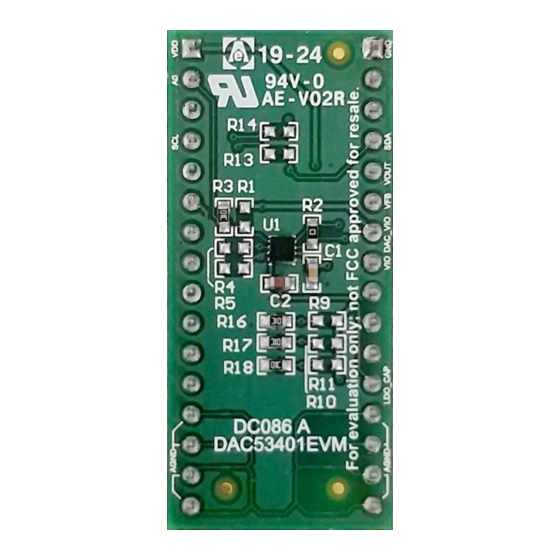
Schematic, PCB Layout, and Bill of Materials www.ti.com Figure 25. BOOSTXL-DAC-PORT Bottom Layer Figure 26. DAC53401EVM PCB Components Layout DAC53401EVM SLAU805 – July 2019 Submit Documentation Feedback Copyright © 2019, Texas Instruments Incorporated... -
Page 27: Dac53401Evm Layers
Schematic, PCB Layout, and Bill of Materials www.ti.com Figure 27. DAC53401EVM Layers SLAU805 – July 2019 DAC53401EVM Submit Documentation Feedback Copyright © 2019, Texas Instruments Incorporated... -
Page 28: Boostxl-Dac-Port Bill Of Materials
R27, R28, R32, R35, R39, R41, R42, R45 R7, R9, R30, R33, R36 1.0k RES, 1.0 k, 5%, 0.1 W, 0603 CRCW06031K00JNEA Vishay-Dale AEC-Q200 Grade 0, 0603 DAC53401EVM SLAU805 – July 2019 Submit Documentation Feedback Copyright © 2019, Texas Instruments Incorporated... - Page 29 R15, R16, R38, R43, RES, 0, 5%, 0.1 W, 0603 0603 RC0603JR-070RL Yageo America R40, R44 RES, 33, 5%, 0.1 W, 0603 CRCW060333R0JNEA Vishay-Dale AEC-Q200 Grade 0, 0603 SLAU805 – July 2019 DAC53401EVM Submit Documentation Feedback Copyright © 2019, Texas Instruments Incorporated...
-
Page 30: Dac53401Evm Bill Of Materials
Schematic, PCB Layout, and Bill of Materials www.ti.com DAC53401EVM Bill of Materials Table 14. DAC53401EVM Bill of Materials Designator Quantity Value Description Package Reference Part Number Manufacturer !PCB Printed Circuit Board DC086 C1, C3, C4, C5 0.1uF CAP, CERM, 0.1 uF, 25... - Page 31 TI products. TI’s provision of these resources does not expand or otherwise alter TI’s applicable warranties or warranty disclaimers for TI products. Mailing Address: Texas Instruments, Post Office Box 655303, Dallas, Texas 75265 Copyright © 2019, Texas Instruments Incorporated...
Need help?
Do you have a question about the DAC53401EVM and is the answer not in the manual?
Questions and answers