
Related Manuals for RADEMACHER 3650 05 12


Summary of Contents for RADEMACHER 3650 05 12
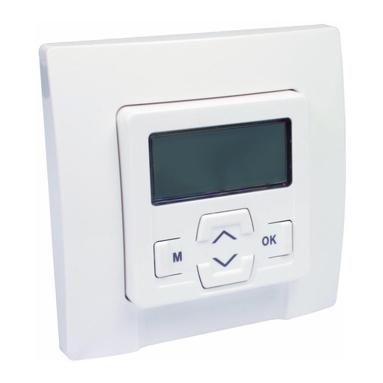
- Page 1 SpeedTimer Translation of Operating and Assembly Manual for 50 mm Switch Ranges Item no. 3650 05 12 VBD 587-2 (12.21)
-
Page 2: Table Of Contents
Table of Contents 1. This manual ............3 16. [AUTO] automatic mode and [ ] manual 21.4 Menu 6.4 - Configuring the blockage 2. Included in delivery ..........4 mode ..............23 detection [ ] .........42 3. Overall view - controls and installation housing ...5 16.1 Menu 1 - Switching between [AUTO] auto- 21.5 Menu 6.5 - Activating/deactivating the 4. -
Page 3: This Manual
1. This manual ..describes how to install, connect and operate the SpeedTimer. Before you begin, please read this manual through completely and follow all the safety instructions. This manual is part of the product. Please store it in an easily accessible place. -
Page 4: Included In Delivery
2. Included in delivery Legend 1. Operating unit (50 x 50) mm 2. Frame 3. Installation housing 4. Light sensor (optional); item no. 7000 00 88 * 5. 2 x assembly screws (not illustrated) 6. 1 x operating manual (not illustrated) * Not included 4. -
Page 5: Overall View - Controls And Installation Housing
3. Overall view - controls and installation housing 13. Installation housing 7. Display Up button 14. Connecting terminals Menu button Down button 11. Connection socket for the light sensor. OK button... -
Page 6: Display Symbols
4. Display symbols MO (MON)... SO (SUN) - weekdays - time / setting parameters Blockage detection OFFSET (for astro time) PLZ - postcode Week programme NORMAL/ASTRO/SENSOR - AUTO - automatic mode switching time modes Automatic slat adjustment ACTUAL value L - not assigned T - jog mode Direction of travel - up / down Settings... -
Page 7: Hazard Symbols
5. Hazard symbols Symbols and depictions used Risk of fatal electric shock. This symbol warns of danger when working on electrical con- Further useful nections, components, etc. It requires that safety precautions information be taken to protect the life and health of the person concerned. Please read the operating manual of the external device described at this point (e.g. -
Page 8: Safety Instructions
6. Safety instructions There is a risk of fatal injury from electric shock when Incorrect use leads to an increased risk of working on all electrical systems. injury. ◆ The electrical connection and all work on electrical systems ◆ Train all personnel to use the SpeedTimer safely. must only be carried out by a qualified electrician in ac- ◆... -
Page 9: Intended Use
7. Intended use Only use the manufacturer's original spare parts. Only use the SpeedTimer for connecting and controlling a tubular motor for: ◆ By doing so, you avoid the risk of malfunctions and damage ◆ Roller shutters to the device or the connected tubular motor. ◆... -
Page 10: Improper Use
8. Improper use Using the SpeedTimer for purposes other than previously men- There is a risk of fatal injury caused through short circuit- tioned is impermissible. ing and electric shocks if the SpeedTimer is used outside. ◆ Do not install and use the SpeedTimer outside. 9. - Page 11 9. Functional description Installation JUNG CD 500 / ST 550 / LS 990 / CDplus as per CD but with coloured rings You can integrate the SpeedTimer into most commercially available switch and frame ranges. MERTEN M1 / Atelier / Artec / Trancent / Antique New PEHA Standard / Dialog / Aura...
-
Page 12: Overview Of Functions
9.1 Overview of functions ◆ Installation wizard for easy commissioning. ◆ Automatic dusk function (via a light sensor) with a cut-off time (“latest at xx:xx hours”). ◆ Configurable blockage detection for mechanical tubular motors. * ◆ Automatic sun function (via a light sensor) ◆... -
Page 13: Important Information Prior To The Electrical Connection And Installation
10. Important information prior to the electrical connection and installation The installation and elec- You must configure the end stops of the tubular motor trical connection may only prior to installation and before making the final electrical be undertaken using the connection. - Page 14 10. Important information prior to the electrical connection and installation Parallel connection of electronic tubular motors Parallel connection of mechanical tubular motors You can connect a maximum of 2 electronic tubular motors in A cut-off relay is required in order to connect mechanical tubular parallel to the SpeedTimer.
-
Page 15: Safety Instructions For The Electrical Connection
11. Safety instructions for the electrical connection There is a risk of fatal injury from electric shock when Incorrect wiring may lead to short circuits and destroy working on all electrical systems. the device. ◆ The electrical connection and all work on electrical systems ◆... -
Page 16: Electrical Connection Of The Speedtimer
12. Electrical connection of the SpeedTimer MOTOR... -
Page 17: Installation
13. Installation The SpeedTimer is intended for flush-mounting. We recommend Installation procedure: using a deep box. Switch off the mains. You will need: Make the electrical connection according to the wiring diagram 1 x 58 mm flush-mounted box (see page 16). Route the power cables to the flush-mounted box. -
Page 18: Important Information Prior To Configuration
14. Important information prior to configuration The button functions: All of the settings are menu-driven. In other words, you will be prompted to carry out the required settings in a logical sequence Menu button, [M] button as shown on the display. ◆... -
Page 19: Brief Description Of The Standard Display
14.1 Brief description of the standard display and main menu The standard display (example) Main menu ◆ Displays the current date and time. ◆ Enables display and selection of the menu items and individual functions. ◆ Displays the set mode and active functions. ◆... -
Page 20: Introduction To Opening And Closing
14.2 Introduction to opening and closing the menus Pressing the [M] button Press for 1 second. in the standard display Pressing the [M] but- approx. causes the main menu ton from any menu to open. will return you to the standard display. -
Page 21: Initial Commissioning With The Help Of The Installation Wizard
15. Initial commissioning with the help of the installation wizard An installation wizard is available in order to help you configure Configuration sequence for the installation wizard: the controller quickly and easily. This automatically guides you through the initial configuration process for the initial commis- Set the time. - Page 22 15. Initial commissioning with the help of the installation wizard Set and confirm the Configure the switching postcode. time mode for “Down”. Switching time mode, see page 25. Set and confirm the “Up” opening time. Confirm the switching time mode and return to the standard display.
-
Page 23: Auto] Automatic Mode And [ ] Manual Mode
16. [AUTO] automatic mode and [ ] manual mode Automatic mode Manual mode Symbol on the standard display Symbol on the standard display Automatic mode is active, all automatic functions are switched ◆ All automatic functions are deactivated; only manual on, e.g.: operation is still possible. -
Page 24: Menu 1 - Switching Between [Auto] Automatic Mode And [ ] Manual Mode
16.1 Menu 1 - Switching between [AUTO] automatic mode and [ ] manual mode Open the main menu. Switching directly on the standard display You can also switch between automatic and manual modes on the standard display. Select and open menu “1”... -
Page 25: Opening And Closing Times [ ]
17. Opening and closing times [ ] ◆ ASTRO The configured opening and closing times apply to all days of Closing time calculation via an astro programme. the week. The closing time is calculated in relation to the date and Mode for the "Down"... - Page 26 17. Opening and closing times [ ] ◆ SENSOR Configuring opening and closing times with an active The closing time is controlled by a light sensor in week programme relation to the level of brightness. If the week programme is activated (see page 41), it is In addition, the measured dusk value is linked to the previ- possible to configure customised opening and closing times for ously configured closing time.
-
Page 27: Menu 2 - Configuring Opening And Closing Times [ ]
17.1 Menu 2 - Configuring opening and closing times [ ] Open the main menu. Set and confirm an open- ing time. Select and open menu “2” [ ] switching Set and confirm a closing times. time. Select and confirm the desired setting. - Page 28 17.1 Menu 2 - Configuring opening and closing times [ ] If [ASTRO] is selected The calculated dusk can be individually customised by means in point 6, the current of an offset of between –60 and +60 minutes. This can be closing time calculated configured in menu 3, see page 32.
-
Page 29: Automatic Dusk Function
18. Automatic dusk function Automatic dusk The automatic dusk function causes the roller shutter to close function with the automatically. It is possible to select between two different astro programme automatic dusk functions using: ◆ the astro programme ◆ the connected light sensor Both functions can be linked to a switching time. - Page 30 18. Automatic dusk function Automatic dusk ◆ The automatic dusk function via a light sensor is only function with a con- executed once a day. nected light sensor ◆ The automatic dusk function is activated daily at 12:01 At dusk, the roller shutter hours.
-
Page 31: Menu 3 - Customising The Automatic Dusk Function [ ]
18.1 Menu 3 - Customising the automatic dusk function [ ]. Open the main menu. Customisation in switch- ing time mode [Normal] No customisation is Select and open menu required in [NORMAL] “3” [ ] Automatic dusk switching time mode. function. - Page 32 18.1 Menu 3 - Customising the automatic dusk function [ ]. Customising the offset Customising the dusk in [ASTRO] switching limit value in [SENSOR] time mode. switching time mode. Example ACTUAL value If the set limit is not met The offset function can be With a negative offset, for exam- Measured brightness.
-
Page 33: Automatic Sun Function
19. Automatic sun function Automatic lowering The automatic sun function enables brightness-dependent 10 min. of control of the roller shutter using a light sensor. To do this, the If the light sensor detects sunshine light sensor is secured to the window pane and then plugged uninterrupted sunshine into the SpeedTimer. - Page 34 19. Automatic sun function Automatic clearing The delay time for moving the shutter down (10 minutes) can After 20 After approx. 20 minutes, be exceeded in the event of changing weather conditions. min. the roller shutter is auto- The automatic sun function is cancelled in the event of matically raised a small manual operation or if an automatic function is triggered amount to uncover the...
-
Page 35: Menu 4 - Configuring The Automatic Sun Function [ ]
19.1 Menu 4 - Configuring the automatic sun function [ ]. Customising the sun set Open the main menu. limit. If the set limit is exceeded, Select and open menu ACTUAL value the roller shutter lowers “4” [ ] Automatic sun Measured brightness. -
Page 36: Random Function [ ]
20. Random function [ ] The random function enables a random delay of the configured The corresponding symbol flashes on the standard display when switching times of between 0 and 30 minutes. the random function is activated, during the period that the movement command is being delayed. -
Page 37: Menu 5 - Configuring The Random Function [ ]
20.1 Menu 5 - Configuring the random function [ ] Open the main menu. Select and open menu “5” [ ] Random function. Select and confirm the desired setting. On = Random function > Back to main menu > Back to main menu OFF = Random function... -
Page 38: Menu 6 - System Settings [ ]
21. Menu 6 - System settings [ ] The following configurations are possible: This menu enables you to configure additional system settings in order to customise the SpeedTimer to your individual preferences. 6.1 Setting the time and date 6.2 Entering the postcode (PLZ) 6.3 Activating/deactivating the week programme In order to do this, open menu 6 6.4 Configuring the blockage detection... -
Page 39: Menu 6.1 - Setting The Time And Date [ ]
21.1 Menu 6.1 - Setting the time and date [ ] Select and open menu Set and confirm the “6.1” [ ] “Time and year. date”. Setting range: 2000 to 2099 Set and confirm the time. Then the “System Pressing and holding a settings”... -
Page 40: Menu 6.2 - Entering The Postcode [Plz]
21.2 Menu 6.2 - Entering the postcode [PLZ] Select and open menu ◆ Only the first two digits of the code are entered for “6.2” [ ] “Postcode”. German towns and cities. ◆ Please refer to the time zone table on page 58 for various European cities. -
Page 41: Menu 6.3 - Activating/Deactivating The Week Programme [ ]
21.3 Menu 6.3 - Activating/deactivating the week programme [ ] If the week programme is activated [On], it is possible to configure Select and open menu a customised opening and closing time for every day of the week. “6.3” [ ] “Week programme”. -
Page 42: Menu 6.4 - Configuring The Blockage Detection [ ]
21.4 Menu 6.4 - Configuring the blockage detection [ ] Brief description of the blockage detection Select and open menu “6.4” [ ] “Blockage The SpeedTimer is able to monitor the torque of motors equipped detection”. with mechanical end point setting. This enables the controller to switch off the motor in the event of overloading or blockage. - Page 43 21.4 Menu 6.4 - Configuring the blockage detection [ ] Select and confirm the Setting and confirming appropriate motor type. the sensitivity level. To do so, please refer to It may be necessary to customise the cut-off the operating manual for the respective tubular sensitivitydepending motor.
- Page 44 21.4 Menu 6.4 - Configuring the blockage detection [ ] Activating / deactivating Test runs should be made to ascertain the highest possible reversing after a block- level of sensitivity, in order to protect the roller shutter in the age is detected. event of blockage.
- Page 45 21.4 Menu 6.4 - Configuring the blockage detection [ ] Automatic reversing in the event of a blockage. As soon as the previous setting is confirmed, In the event of a blockage, the motor runs in the opposite direction the “System settings” for approx.
-
Page 46: Menu 6.5 - Activating/Deactivating The Automatic Summer/Winter Changeover
21.5 Menu 6.5 - Activating/deactivating the automatic summer/winter changeover The SpeedTimer features an automatic summer/winter change- ◆ If switching times have been programmed between over function. 2:00 hours and 03:00 hours, they will either be executed twice (changeover from summer time to winter time) or When is the clock altered? not at all (changeover from winter time to summer ◆... - Page 47 21.5 Menu 6.5 - Activating/deactivating the automatic summer/winter changeover Select and open menu Then the “System set- “6.5” “Summer/winter tings” menu will be changeover”. displayed again. Activate or deactivate the summer/winter changeover and con- firm. On = activated OFF = deactivated...
-
Page 48: Menu 6.6 - Configuring The Total Running Time And Venetian Blind Mode [ T ]
21.6 Menu 6.6 - Configuring the total running time and Venetian blind mode [ T ] If the SpeedTimer is being used to control a Venetian blind, the If blockage detection is activated (see page 42), it is not controller can be configured correspondingly. necessary to configure the total running time as the control- ler will detect when the end point is reached. - Page 49 21.6 Menu 6.6 - Configuring the total running time and Venetian blind mode [ T ] Brief description of the automatic slat adjustment Select and open menu function “6.6” “Total running time / Venetian blind Automatic slat adjustment is a function for operating a Venetian mode”.
- Page 50 21.6 Menu 6.6 - Configuring the total running time and Venetian blind mode [ T ] Activate or deactivate Confirm the previous setting and return to jog mode and the "System settings" confirm. menu. On = Jog mode > Continue with point 4. activated >...
-
Page 51: Menu 6.7 - Displaying Software Version
21.7 Menu 6.7 - Displaying software version Select and open menu Confirm the previous “6.7” “Software display and return to version”. the "System settings" menu. The current software version is displayed. Display range: 1.00 to 99.99... -
Page 52: Software Reset (Restore The Default Factory Settings)
22. Software reset (restore the default factory settings) Press and hold all four buttons for 5 seconds 5 seconds simultaneously until all symbols are shown on the display. Then the software version of the device will be displayed for a few seconds. -
Page 53: Performing A Hardware Reset
23. Performing a hardware reset A hardware reset can be performed in the event that the SpeedTimer fails to react to commands. In order to do so, the operating unit of the controller must be pulled out of the installation housing. An opening is located on the rear side of the operating unit. -
Page 54: Dismantling
24. Dismantling Dismantling procedure: There is also a risk of fatal electric shock while disman- Switch off the mains. tling the SpeedTimer. Observe the safety instructions for the electrical connection on Secure the connector against reconnection and check that the page 15. -
Page 55: Simplified Eu Declaration Of Conformity
25. Simplified EU declaration of conformity RADEMACHER Geräte-Elektronik GmbH hereby declares The full text of the declaration of conformity is available at that the SpeedTimer (item no. 3650 05 12) complies with the the following website: Directive 2014/35/EU Low-voltage Directive and 2014/30/EU www.rademacher.de/ce... -
Page 56: Technical Specifications
26. Technical specifications External dimensions: 50 x 50 mm Colour: Ultra-white, glossy Nominal voltage: 230 V ~ / 50 Hz Max. switching capacity: 8 (4) A µ (Type 1B) Standby consumption: < 0.6 W Connection diameter: 1.5 mm² Installation depth: 34 mm Permissible ambient temperature: 0 to 40°C... -
Page 57: Factory Settings
27. Factory settings Automatic mode: Automatic summer/ winter changeover: Automatic timer: Total running time: 150 sec. Up time: 07:00 hours Jog mode: Down time: 20:00 hours, "Normal" mode Tilting time off (1.50 seconds) Automatic sun function: Random function: Time / date: 12:00 hours / 01.01.2018 Postcode (PLZ): Week programme:... -
Page 58: Time Zone Table
28. Time zone table Belgium Great Britain France 146 Milan Luxembourg 171 Baden 101 Antwerp 116 Aberdeen 130 Bordeaux 147 Naples 158 Luxembourg 172 Braunau 102 Bruges 117 Birmingham 131 Brest 148 Palermo 173 Brixen The Netherlands 103 Brussels 118 Bristol 132 Dijon 149 Rome 174 Bruck/Mur... - Page 59 28. Time zone table 188 Krakow 203 Zurich 218 Badajoz 235 Valencia 251 Sarajevo 189 Lodz 219 Burgos 236 Valladolid 252 Sofia Sweden 190 Lublin 220 Cáceres 237 Vitoria 253 Skopje 204 Boras 191 Poznan 221 Castellón 238 Zaragoza 254 Thessaloniki 205 Gavle 192 Szczecin 222 Granada...
-
Page 60: Menu Overview
29. Menu overview Main menu 1. Submenu 2. Submenu 3. Submenu Automatic mode > On / OFF Opening and closing > Opening time > On time > Closing time > OFF + NORMAL + ASTRO + SENSOR Automatic dusk > - - - if [Normal] function >... - Page 61 29. Menu overview Main menu 1. Submenu 2. Submenu 3. Submenu Automatic sun > On > Set limit function [31 - 45] > OFF Random function > On / OFF System settings > Time > 6.1 Time/date > Date > Year >...
- Page 62 29. Menu overview Main menu 1. Submenu 2. Submenu 3. Submenu System settings > 6.4 Blockage detection > On / OFF > Motor type > Set limit [1 - 6] > Reversing [On / OFF] > On / OFF > 6.5 Summer/winter changeover >...
- Page 64 RADEMACHER Geräte-Elektronik GmbH Buschkamp 7 46414 Rhede (Germany)
Need help?
Do you have a question about the 3650 05 12 and is the answer not in the manual?
Questions and answers