RADEMACHER Troll Standard 5620 Instruction Manual
Source: rademacher.de
Hide thumbs
Also See for Troll Standard 5620:

Related Manuals for RADEMACHER Troll Standard 5620


Summary of Contents for RADEMACHER Troll Standard 5620
- Page 1 Troll Standard Instruction manual for the electrical connection and for commissioning Item no. 3650 03 12 (ultra white) / 3650 03 22 (aluminium) Type: 5620 VBD 592-2 (01.21)
-
Page 2: Table Of Contents
Contents This manual..................4 How to use this manual ..............4 Hazard symbols ................... 5 Levels of danger and signal words..........5 Symbols and depictions used............6 Safety instructions ................7 Intended use ..................8 Improper use ..................8 Expert knowledge required by the installer ......8 Included in delivery ................ - Page 3 Contents 13. Manual operation ................33 14. Memory function - accepting the current time as switching time ................34 15. Menu overview ..................35 16. Menu 1 - Switching automatic mode on/off ........36 17. Switching times (opening and closing times) [ / ], brief description ................37 17.1 Menu 2 - Configuring opening and closing times [ / ] ..
-
Page 4: This Manual
1. This manual..describes how to install, connect the electrical system and operate the Troll Standard. 1.1 How to use this manual ◆ Before you begin, please read this manual through completely and follow all the safety instructions. ◆ Please also read the instruction manuals for the accessories (if avail- able) as well as the manuals for the respective connected electrical appliances. -
Page 5: Hazard Symbols
2. Hazard symbols The following hazard symbols are used in this manual: Danger of fatal electric shock Danger area / dangerous situation 2.1 Levels of danger and signal words DANGER! This hazard will lead to serious injury or death if not avoided. WARNING! WARNING! This hazard may result in serious injury or death if not avoided. -
Page 6: Symbols And Depictions Used
2.2 Symbols and depictions used Other useful information Please read the respective manual Procedures ◆ Itemisation or a) Lists Activated menu symbols and setting parameters flash on the display. Information about opening the menus and setting the parameters can be found on page 29. -
Page 7: Safety Instructions
3. Safety instructions There is a risk of fatal electric shock when touching electrical components. ◆ The electrical connection and all work on electrical systems must only be carried out by a qualified electrician in accordance with the connection instructions in these operating instructions. ◆... -
Page 8: Intended Use
3.1 Intended use Use the Troll Standard only for connecting and controlling a tubular motor for roller shutters, Venetian blinds, slats or awnings. Operating conditions ◆ The tubular motor must be fitted with a mechanical or electronic end position switch. ◆... -
Page 9: Included In Delivery
4. Included in delivery Included in delivery 1 x Operating unit (50 x 50 mm) 1 x Frame 1 x Installation housing 1 x Instruction manual (not illustrated) After unpacking please check and compare ..the contents of the package with those specified above. -
Page 10: General View Of The Operating Unit
5. General view of the operating unit Pos. Symbol Description Operating unit Display Menu button ◆ Open the main menu ◆ Back to the previous menu or standard display Setting buttons ◆ Select a menu in the main menu ◆ Set the parameters (more / less) Short press or press and hold = ●... - Page 11 General view of the operating unit Pos. Symbol Description OK button ◆ Open the selected menu ◆ Confirm and save settings ◆ Continue to the next setting Operating buttons Up / Down ◆ Manual operation SET/Stop button ◆ Manual stop of the roller shutter travel ◆...
-
Page 12: General View Of The Installation Housing
5.1 General view of the installation housing Pos. Symbol Description Installation housing Claw fasteners and screws Connecting terminals Type plate... -
Page 13: Electrical Connections
5.2 Electrical connections Pos. Symbol Description E1 / E2 External inputs - optional Connect external signal transmitters or external controllers (e.g. Troll Comfort), see page 26. L / N Power supply - 230 V / 50 Hz Connect the supply voltage. Rotation direction (up / down) Connecting cables to the tubular motor. -
Page 14: Display And Its Symbols
5.3 Display and its symbols Symbol Description MO ... SO Weekdays (Monday ... Sunday) Time / setting parameters Information Switching time programme Setting AUTO Automatic mode Ist-Wert Direction of travel (up/down) Automatic mode off Switching times Random function System settings Blockage detection Automatic button lock... -
Page 15: Product Description
6. Product description The Troll Standard controller is designed for controlling roller shut- ters, Venetian blinds, slats or awnings by connecting a corresponding tubular motor. Roller shutter control The device enables the roller shutter to be automated. Manual operation It is possible to manually control the connected tubular motor at any time by using the controls. -
Page 16: Description Of The Safety Functions
6.1 Description of the safety functions Blockage detection The Troll Standard is able to monitor the torque of motors equipped with a mechanical end point setting. This enables the controller to switch off the motor in the event of overloading or blockage, see page 44. 6.2 Overview of functions ◆... -
Page 17: Automatic Summer / Winter Changeover
Overview of functions ◆ Memory function (easy acceptance of the current time as switching time) ◆ Switch reversal of rotation direction on/off ◆ Automatic summer / winter changeover ◆ Permanent storage of the settings ◆ External control via the two inputs E1 / E2 ◆... -
Page 18: Technical Specifications
7. Technical specifications Mains supply [ L / N ] Mains supply 230 V / 50 Hz voltage: Consumption: Standby: < 0.6 W 2 x extension inputs [ E1 / E2 ] onnection of external signal transducers/eternal controllers Input voltage: 230 V / 50 Hz (Ri = 200 kW) Maximum cable length:... - Page 19 Technical specifications General information External dimensions (W x H x D) 50 x 50 x 12 mm Operating unit [ 1 ]: according to DIN 49075 Ultra-white (UW), Available colours: Aluminium (AL) Installation depth: 32 mm Permissible ambient 0 °C to + 40 °C temperature range: Protection class: II (only for use in dry rooms)
-
Page 20: Werkseinstellungen
7.1 Werkseinstellungen Factory settings Automatic mode: Switching times: Date: 01.07.2018 Time: 12:00 Up-time and mode: 7:00 Down-time and mode: 20:00 Random function: Switching time programme: Blockage detection: - Motor type: 2 (45 mm / 30 Nm) - Sensitivity: 2 30 - Reversing function: Automatic summer / winter changeover:... -
Page 21: Conduct In The Event Of A Power Failure
7.2 Conduct in the event of a power failure Power reserve (approx. 8 hours) The current time flashes for approx. 5 minutes in the event of a power failure and the Troll Standard changes to power reserve. Time and date after a power failure The power reserve is approx. -
Page 22: Safety Instructions For The Electrical Connection
8. Safety instructions for the electrical connection Prior to the electrical connection, check that the voltage / frequency on the type plate corresponds to that of the local mains supply. Follow the electrical connection specifications in the instruction manual of the tubular motor being used or the external controller (when using E1/E2). - Page 23 (electric shocks / short circuiting). ◆ Only use the installation housing provided to connect and install the Troll Standard. ◆ Installation housings of other RADEMACHER products, such as other Troll controllers, are not compatible. WARNING! WARNING! Connection of a second phase to E1 or E2 will cause the Troll Standard to be damaged.
-
Page 24: Important Information Prior To The Electrical
Parallel connection of electronic tubular motors A maximum of 3 tubular motors can be connected in parallel to the Troll Standard (e.g. RADEMACHER electronic tubular motors). In order to do so, follow the information in the instruction manual of the tubular motor being used.. -
Page 25: Electrical Connection
Important information prior to the electrical connection and installation Maximum cable length for connecting external signal transducers to E1 or E2 The maximum cable length for connecting external signal transducers to E1 or E2 must be 15 metres. Installation materials The Troll Standard is designed for flush-mounted installation. - Page 26 Connecting the white set lead (SET) from RADEMACHER tubular motors * The white set lead (SET) from RADEMACHER tubular motors must be connected to the neutral terminal [ N ] to ensure trouble-free opera- tion of the tubular motor..
-
Page 27: Installation After The Electrical Connection
9. Installation after the electrical connection Insert the installation housing into the flush-mounted box and fasten it with the screws of the claw fasteners. Place the frame onto the installation housing. Then carefully insert the operating unit into the installation housing . Switch on the mains power supply again.. -
Page 28: Brief Description Of The Standard Display And Main Menu
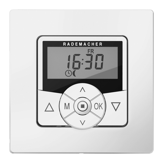
10. Brief description of the standard display and main menu The standard display (example) ◆ Displays the current day of the week and time. ◆ Displays the activated functions. ◆ Manual operation of the Troll Standard is only possible from the standard display. -
Page 29: Introduction To Opening The Menus And Setting The Functions
11. Introduction to opening the menus and setting the functions Open the main menu. Pressing the menu button on the standard display opens the main menu. Select the desired menu or menu number. The selected menu is indicated by a flashing symbol. - Page 30 11. Introduction to opening the menus and setting the functions Each setting must be confirmed with the OK button. Confirming the entry takes you to the next setting or back to the menu. Back to the standard display. Example Pressing the menu button briefly takes you back one menu step.
-
Page 31: Initial Commissioning With The Help Of The Installation Wizard
12. Initial commissioning with the help of the installation wizard The installation wizard, which guides you through the first basic settings, is automatically started for the initial commissioning or after a software reset. Quitting the installation wizard Pressing the M button for one second causes the installation wizard to be cancelled prematurely. - Page 32 12. Initial commissioning with the help of the installation wizard Set and confirm the closing time [ ]. Pre-setting: MO...SO (MON...SUN) * * The opening time and the closing time applies to the entire week. If necessary, you can subsequently select one of two switch- ing time programmes in menu 9.5, see page 43.
-
Page 33: Manual Operation
13. Manual operation Manual operation is possible from the standard display at any time and has priority over the programmed automatic functions. Example for manual control of a roller shutter Open the roller shutter. Pressing the button briefly causes the roller shutter to move to the upper end point. -
Page 34: Memory Function - Accepting The Current Time As Switching Time
14. Memory function - accepting the current time as switching time The memory function enables you to easily adapt the switching times during the course of the year by allowing the current time to be accepted as the switching time, without having to access the switching time menu. If weekday and weekend switching times are activated [ MO...FR / SA+SO ] the newly accepted switching time will only apply to the current group of days, e.g. -
Page 35: Menu Overview
15. Menu overview Main menu Symbol Menu Page AUTO Automatic mode ..........36 Switching times ..........37 Random function ..........40 System settings ..........41 Time and date ........... 42 Switching time programme ........43 Blockage detection ..........44 Device settings ..........47 9.8.1 Automatic summer / winter changeover .......... -
Page 36: Menu 1 - Switching Automatic Mode On/Off
16. Menu 1 - Switching automatic mode on/off AUTO Automatic mode on (symbol on the standard display) ◆ All set automatic functions are active ◆ Manual operation is also possible in automatic mode Automatic mode off (symbol on the standard display) ◆... -
Page 37: Switching Times (Opening And Closing Times) [ / ], Brief Description
17. Switching times (opening and closing times) [ / ], brief description You can configure various opening [ ] and closing times [ ] for the Troll Standard in order to open or close your roller shutter automatically at your preferred times. For this purpose, there are three switching time programmes available in menu 9.5, see page 43: [ 1 ] Weekly switching times (factory setting) -
Page 38: Menu 2 - Configuring Opening And Closing Times [ / ]
17.1 Menu 2 - Configuring opening and closing times [ / ] If the type of switching time programme (weekly switching times, working day / weekend switching times) is not to be changed, start directly with point 2. If you want to change the type of switching time programme, first open menu 9.5, see page 43 and configure the desired switching time programme. - Page 39 17.1 Menu 2 - Configuring opening and closing times [ / ] The following serves to describe the procedure for setting an opening and closing time [ / ] as weekly switching times. Set and confirm an opening time [ ]. Set and confirm the closing time [ ].
-
Page 40: Menu 6 - Configuring The Random Function
18. Menu 6 - Configuring the random function The random function enables a random delay of the set timer periods ranging between 0 and 30 minutes. The random function is executed for: All automatic opening and closing times. Please note the state of the cube symbol on the standard display The cube symbol flashes on the standard display when the random function is activated during the period in which the movement command is being delayed. -
Page 41: Menu 9 - System Settings
19. Menu 9 - System settings This menu enables you to configure additional devices and system settings to customise your Troll Standard to your individual preferences. Menu 9 - System settings Symbol Menu Page Time and date ........... 42 Switching time programme ........43 Blockage detection .......... -
Page 42: Menu 9.1 - Setting The Time And Date
19.1 Menu 9.1 - Setting the time and date Open menu 9.1. Configure and confirm the desired settings. Setting order: Time Date Day.Month Year 2000 to 2099... -
Page 43: Menu 9.5 - Configuring The Switching Time Programme
19.2 Menu 9.5 - Configuring the switching time programme The number of opening and closing times that can be configured de- pends on the desired switching time programme selected in this menu. There are two switching time programmes available: [ 1 ] Weekly switching times (factory setting) [ / ] The switching times apply from (MO .. -
Page 44: Menu 9.6 - Configuring The Blockage Detection
19.3 Menu 9.6 - Configuring the blockage detection The Troll Standard is able to monitor the torque of motors equipped with a mechanical end point setting. This enables the controller to switch off the motor in the event of overloading or blockage. As a result, the roller shutter is protected from damage. - Page 45 19.3 Menu 9.6 - Configuring the blockage detection Ø Motor types | Power 1 06 | 35 mm | 6 Nm 1 10 | 35 mm | bis 10 Nm 2 10 | 45 mm | bis 10 Nm 2 20 | 45 mm | bis 20 Nm 2 30...
- Page 46 19.3 Menu 9.6 - Configuring the blockage detection Automatic reversing function in the event of a blockage In the event of a blockage, the motor immediately runs in the opposite direction for approx. 2 seconds to release the roller shutter. More information about the blockage detection: ◆...
-
Page 47: Menu 9.8 - Device Settings
20. Menu 9.8 - Device settings Menu 9.8 - Device Settings Symbol Menu Page 9.8.1 Automatic summer / winter changeover ..........48 9.8.2 Display contrast ..........49 9.8.4 Timer mode ............49 9.8.5 Button lock ............50 9.8.7 Reversal of rotation direction ......51 9.8.0 Software version .......... -
Page 48: Menu 9.8.1 - Switching The Automatic Summer/Winter
20.1 Menu 9.8.1 - Switching the automatic summer/winter time on/off The Troll Standard features an automatic summer/winter changeover function. Summer time The timer is changed to summer time on the last Sunday in March. The timer is set back one hour at 02:00 hours. Winter time The timer is changed to winter time (standard time) on the last Sunday in October. -
Page 49: Menu 9.8.2 - Setting The Display Contrast
20.2 Menu 9.8.2 - Setting the display contrast Open menu 9.8.2. Set and confirm the desired contrast. 1 = low contrast 10 = high contrast 20.3 Menu 9.8.4 - Setting the timer mode This menu enables you to configure the time base for the internal timer (depending on the local power supply). -
Page 50: Menu 9.8.5 - Switching The Button Lock On / Off
20.4 Menu 9.8.5 - Switching the button lock on / off You can activate the automatic button lock to protect against any unin- tentional input. Open menu 9.8.5. Activate/deactivate the button lock and confirm. On = button lock on Off = button lock off Automatic activation after approx. -
Page 51: Menu 9.8.7- Switching The Reversal Of Rotation Direction On/Off
20.5 Menu 9.8.7 - Switching the reversal of rotation direction on/off It is not necessary to re-wire the motor if the direction of rotation of the connected motor is wrong ([ UP ] button moves the roller shutter downwards and [ Down ] button moves the roller shutter upwards). The direction of the motor can be easily changed using the reversal of rotation direction function. -
Page 52: Menu 9.8.0 - Displaying The Software Version
20.6 Menu 9.8.0 - Displaying the software version This menu enables the current Troll Standard software version to be displayed. Open menu 9.8.0. The current software version is subsequently displayed. Display the device version. S = „Troll“ Standard Perform a display test. Return to menu 9.8 - Device settings. -
Page 53: Deleting All Settings, Software Reset
21. Deleting all settings, software reset A software reset can be performed to reset the Troll Standard to the original default condition as when supplied. Press and hold the four buttons simultaneously for 5 seconds until all the symbols are shown on the display. -
Page 54: Performing A Hardware Reset
22. Performing a hardware reset A hardware reset can be performed in the event that the Troll Standard no longer react to commands. To do so, pull the operating unit out of the installation housing. The centre section on the rear of the operating unit contains an opening with two contacts that must be carefully bridged... -
Page 55: Error Messages
23. Error messages Error 2 (display „E2“) Internal device error highlighting that the Troll Standard may be defective. ◆ Please then contact RADEMACHER Service, see page 60. 24. Dismantling DANGER! There is a risk of fatal electric shock when touching electrical components. -
Page 56: Simplified Eu Declaration Of Conformity
25. Simplified EU declaration of conformity RADEMACHER Geräte-Elektronik GmbH,hereby declares that the Troll Standard complies with the Directives 2014/35/EU (Low-voltage direcive) and 2014/30/EU (EMC directive). The full text of the declaration of conformity is available at the following website: www.rademacher.de/ce... -
Page 57: Warranty Terms And Conditions
Proof of this must be provided by presenting a copy of the invoice. RADEMACHER will remedy any defects that occur within the warranty period free of charge either by repair or by replacement of the affected parts or by supplying a new replacement unit or one to the same value. - Page 60 RADEMACHER Geräte-Elektronik GmbH Buschkamp 7 46414 Rhede (Germany) info@rademacher.de www.rademacher.de Service: * 30 seconds free of charge, subsequently Hotline 01807 933-171* 14 cents / minute from German fixed line Telefax +49 2872 933-253 networks and max. 42 cents / minute from service@rademacher.de...
Need help?
Do you have a question about the Troll Standard 5620 and is the answer not in the manual?
Questions and answers