Advertisement
Available languages
Available languages
Quick Links
H-9648, H-9649
H-9650
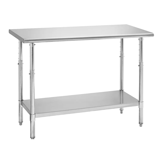
ADJUSTABLE HEIGHT
STAINLESS STEEL
WORKTABLE
TOOLS NEEDED
Phillips
5/32" Allen
Screwdriver
Wrench
(included)
Tabletop x 1
Undershelf x 1
Outer Leg Tube
Flange
Nut
Phillips Head Bolt
Inner Leg Tube
Flange
Nut
Phillips Head Bolt
Gusset
PAGE 1 OF 9
1-800-295-5510
uline.com
10 mm
Flathead
Wrench
Screwdriver
(optional)
ASSEMBLY
Figure 1
Tabletop
Rubber
Mallet
(optional)
PARTS
Leg Plug x 60
Phillips Head Bolt x 8
(Optional)
Inner Leg Tube x 4
NOTE: If purchased with optional casters,
replace adjustable feet after table assembly
is completed.
NOTE: Assemble unit on a smooth non-marring
surface to prevent scratching.
1.
With tabletop upside down, place inner leg tube in
tabletop gusset. Secure inner leg tube to tabletop
gusset with one Phillips head bolt and flange nut
using Phillips head screwdriver and 10 mm wrench.
(See Figure 1)
2. Place outer leg tube over inner leg tube and set to
preferred height. Secure inner and outer leg tubes
together with one Phillips head bolt and flange nut
using Phillips screwdriver and 10 mm wrench. Set
and secure remaining legs at the same height.
(See Figure 1)
Para Español, vea páginas 4-6.
Pour le français, consulter les pages 7-9.
Flange Nut x 8
Outer Leg Tube with
Adjustable Foot x 4
Set Screw x 8
Caster x 4
(optional)
0422 IH-9648
Advertisement

Related Manuals for U-Line H-9648


Summary of Contents for U-Line H-9648
- Page 1 Para Español, vea páginas 4-6. Pour le français, consulter les pages 7-9. H-9648, H-9649 1-800-295-5510 H-9650 uline.com ADJUSTABLE HEIGHT STAINLESS STEEL WORKTABLE TOOLS NEEDED Phillips 5/32" Allen 10 mm Flathead Rubber Screwdriver Wrench Wrench Screwdriver Mallet (included) (optional) (optional) PARTS...
- Page 2 ASSEMBLY CONTINUED 3. Place tabletop/leg assembly on its side. Figure 2 (See Figure 2) 4. Push tabletop/leg assembly through undershelf collars to desired height. A rubber mallet may be needed to move shelf along leg tubes. To ensure exact height, mark desired height on each leg assembly with magic marker or grease pencil.
-
Page 3: Optional Casters
OPTIONAL CASTERS Flip the table over onto a smooth, non-marring surface. Remove adjustable feet from legs using a flat head screwdriver. (See Figure 5) NOTE: You may need to use a rubber mallet or hammer to assist. Figure 5 2. Hold caster base and rotate nylon bushing clockwise. - Page 4 H-9648, H-9649 800-295-5510 H-9650 uline.mx MESA DE TRABAJO DE ACERO INOXIDABLE DE ALTURA AJUSTABLE HERRAMIENTAS NECESARIAS Desarmador Llave Allen Llave de Desarmador Plano Mazo de de Cruz de 5/32" 10 mm (opcional) Caucho (incluida) (opcional) PARTES 60 Tapones para Pata...
- Page 5 CONTINUACIÓN DEL ENSAMBLE 3. Coloque el ensamble de la cubierta/pata de Diagrama 2 costado. (Vea Diagrama 2). 4. Empuje el ensamble de la cubierta/pata a través de los aros de la repisa inferior hasta la altura deseada. Podría ser necesario un mazo de caucho para deslizar la repisa a lo largo de los tubos de las patas.
- Page 6 RUEDAS OPCIONALES 1. Voltee la mesa sobre una superficie lisa que no deje marcas. Retire las patas ajustables de los tubos usando un desarmador de cabeza plana. (Vea Diagrama 5) NOTA: Podría necesitar un mazo de caucho o martillo para ayudarse. Diagrama 5 2.
-
Page 7: Montage
H-9648, H-9649 1-800-295-5510 H-9650 uline.ca TABLE DE TRAVAIL À HAUTEUR RÉGLABLE EN ACIER INOXYDABLE OUTILS REQUIS Tournevis Clé Allen de Clé de Tournevis à Maillet en cruciforme 5/32 po (inclus) 10 mm tête plate caoutchouc (optionnel) (optionnel) PIÈCES Bouchon de tube Boulon à... - Page 8 MONTAGE SUITE 3. Posez l'ensemble des pieds/de la surface sur le côté. Figure 2 (Voir Figure 2) 4. Passez l'ensemble des pieds/de la surface dans les collets de la tablette inférieure à la hauteur désirée. Un maillet en caoutchouc peut être nécessaire pour faire bouger la tablette le long des tubes de pied.
- Page 9 ROULETTES OPTIONNELLES Retournez la table sur une surface lisse qui ne marque pas. Retirez les pattes réglables des pieds avec un tournevis à tête plate. (Voir Figure 5) REMARQUE : Aidez-vous d'un maillet en caoutchouc ou d'un marteau si nécessaire. Figure 5 2.
Need help?
Do you have a question about the H-9648 and is the answer not in the manual?
Questions and answers