Advertisement
Available languages
Available languages
Quick Links
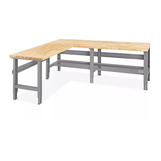
H-9620
96
78" L-SHAPED
X
PACKING TABLES
TOOLS NEEDED
Phillips Head
7/16" Wrench
Screwdriver
Flat Head
Screwdriver
4
1
2
BASE TABLE
1.
Insert adjustable feet (1) into legs (2) and slide into
place at desired height.
NOTE: If desired, insert locking tabs through
legs and adjustable feet to lock feet into place.
2. Place legs (2) in upright position. Legs should be
placed approximately 45" apart.
3. Attach stringers (3) to table legs using center six
holes in back legs. Fasten with 12 bolts, lock washers
and nuts.
PAGE 1 OF 9
1-800-295-5510
uline.com
3/8" Wrench
10 mm Wrench
(For Non-Steel Top Assembly)
Drill
3/16" Drill Bit
(Optional)
(Optional)
LEGS AND FRAME ASSEMBLY
5
3
3
4
8
7
7
#
1
2
3
4
5
6
7
8
6
1/4"-20 x 5/8" Bolt x 28
Lock Washer x 28
4. Place lower shelves (4) across braces of legs. Attach
lower shelves using eight nuts and bolts.
5. Place 96" tabletop (5) on a smooth, non-marring
surface with top side facing down.
6. Flip the assembled frame upside down and line up
with the pre-drilled holes on the bottom side of the
top.
Para Español, vea páginas 4-6.
Pour le français, consulter les pages 7-9.
DESCRIPTION
Adjustable Foot
Leg
96" Stringer – 2-Piece
96" Lower Shelf – 2-Piece
96" Tabletop
L-Leg
48" Stringer
48" Tabletop
Hardware Kit
1/4"-20 Nut x 28
#14 x 3/4" Wood Screw x 46
Locking Tab x 9
QTY
9
4
1
1
1
1
1
1
1021 IH-9620
Advertisement

Related Manuals for U-Line H-9620


Summary of Contents for U-Line H-9620
- Page 1 Para Español, vea páginas 4-6. Pour le français, consulter les pages 7-9. H-9620 1-800-295-5510 uline.com 78" L-SHAPED PACKING TABLES TOOLS NEEDED 3/8" Wrench 10 mm Wrench Phillips Head 7/16" Wrench (For Non-Steel Top Assembly) Screwdriver Flat Head Drill 3/16" Drill Bit...
-
Page 2: Base Table
LEGS AND FRAME ASSEMBLY CONTINUED L-EXTENSION NOTE: Attach L-leg (6) to left side of stringer for right side L-table configuration. Attach to right Insert adjustable feet (1) into leg (2) and L-leg (6) and side of stringer for left side configuration. slide into place at desired height. - Page 3 STEEL TOP ASSEMBLY BASE TABLE Hardware pack includes: DESCRIPTION 1/4"-20 x 5/8" Bolts 1/4"-20 Nuts Lock Washers NOTE: There are four mounting channels provided for installing an optional cabinet or drawer. Figure 4 1. Align leg holes to end of tabletop. Secure with six 1/4"-20 x 5/8"...
-
Page 4: Herramientas Necesarias
H-9620 800-295-5510 uline.mx MESAS DE TRABAJO EN FORMA DE L DE 96 X 78" HERRAMIENTAS NECESARIAS Llave de 3/8" Llave de 10 mm Desarmador Llave de 7/16" (Para Ensamblar la Cubierta que No Sea de Acero) de Cruz Taladro Broca de 3/16"... - Page 5 CONTINUACIÓN DEL ENSAMBLE DE LAS PATAS Y EL ARMAZÓN EXTENSIÓN EN L NOTA: Fije la pata en L (6) en el lado izquierdo del larguero para la configuración derecha de Inserte la base ajustable (1) en la pata (2) y la pata en L la mesa en L.
- Page 6 ENSAMBLE DE LA CUBIERTA DE ACERO BASE DE LA MESA El paquete de la tornillería incluye: DESCRIPCIÓN CANT. Pernos de 1/4"-20 x 5/8" Tuercas de 1/4"-20 Rondanas de Seguridad NOTA: Se proporcionan cuatro canales de instalación para fijar un gabinete o archivero adicionales. Diagrama 4 Alinee los orificios de las patas al extremo de la cubierta.
-
Page 7: Outils Requis
H-9620 1-800-295-5510 uline.ca TABLES D'EMBALLAGE EN L DE 96 X 78 PO OUTILS REQUIS Clé de 3/8 po Clé de 10 mm Tournevis Clé de 7/16 po (Pour le montage d'une surface autre qu'en acier) cruciforme Perceuse électrique Mèche de perceuse Tournevis à... - Page 8 MONTAGE DES PIEDS ET DU CADRE SUITE EXTENSION EN L REMARQUE : Fixez le pied en L (6) sur le côté gauche du longeron pour une configuration de la table en L vers la droite. Fixez-le du côté droit du longeron pour Insérez les pattes réglables (1) dans le pied (2) et le pied en L (6) en les glissant à...
- Page 9 MONTAGE D'UNE SURFACE EN ACIER TABLE DE BASE Le matériel d'installation comprend : DESCRIPTION QTÉ Boulons de 1/4 po-20 x 5/8 po Écrous de 1/4 po-20 Rondelles de blocage REMARQUE : Quatre profilés de montage sont fournis pour l'installation d'une armoire ou tiroir optionnels.
Need help?
Do you have a question about the H-9620 and is the answer not in the manual?
Questions and answers