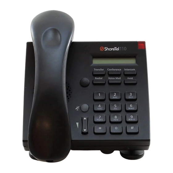
ShoreTel 110 Installation
Wall mount installation for the ip phones and button box
Hide thumbs
Also See for 110:
- User manual (22 pages) ,
- Quick install manual (12 pages) ,
- Quick reference (2 pages)
Advertisement
Wall Mount Installation
for the ShoreTel 110 and 115 IP Phones and BB24 Button Box
Tools Required:
- pencil
- drill
- screwdriver
- studfi nder (optional)
Installing the Wall Mount:
1. Decide where the phone or BB24 will be located. We recommend
mounting near an Ethernet jack.
2. Use a studfi nder to locate the wall stud (skip this step if your are using
"molly" hollow wall anchors).
3. Place the wall mount at the desired location and use the wall mount as
a template. Then, use a pencil to mark where the screws will go.
4. Use a drill to bore a small hole at each pencil mark.
5. Insert screws (or "molly" anchors) into the drilled holes and drive the
screws into the wall until only 1/4 inch remains exposed.
6. Position the wall mount against the wall with the screws protruding.
7. Slide the wall mount downward until it settles into place.
8. Tighten the screws to create a snug fi t.
Mounting the Phone or Button Box:
1. Unplug and remove the handset and stationary base from the
IP phone. (Skip this step if you are installing the BB24.)
2. Plug the Ethernet cable (shipped with the wall mount) into the
RJ-45 port of the phone or BB24 before mounting the device.
(It may be too diffi cult to attach the cable after the device has
been mounted.)
3. Insert the wall mount's upper two tabs into the slots on the
device's rear panel. Then, roll the base of the phone or BB24
toward the lower tabs and snap in place. (Apply upward
pressure on the lower tabs, if necessary.)
4. Reconnect any loose cables and wait for the phone or BB24
to reboot before attempting to place a call.
Exposing the Wall Mount Handset Retainer on the IP 110 or 115:
1. To prevent the phone handset from falling to the fl oor, use your thumb or fi ngernail to pry the wall mount handset retainer
out of its housing (as indicated by the arrow in the left-most section of the illustration below).
2. The retainer is composed of two separate pieces that are held together by a screw. Take a fi rm hold on the lower piece and
then rotate the upper piece 180 degrees.
3. Reinsert the retainer back into the groove such that the tab is now exposed.
ShoreTel, Inc., 960 Stewart Drive Sunnyvale, California 94085 USA Phone: +1.408.331.3300 +1.800.425.9385 Fax: +1.408.331.3333
800-1042-02 Copyright © 1998-2007 by ShoreTel, Inc., Sunnyvale, Californio, U.S.A. All rights reserved.
Also Supplied:
- (4) wood screws
- (4) "molly" hollow wall anchors
- Special Ethernet cable with sharp
bend at the RJ-45 port
Note: The handset
retainer procedure
does not apply to the
BB24 because it does
not have a handset.
www.shoretel.com
Advertisement
Table of Contents


Need help?
Do you have a question about the 110 and is the answer not in the manual?
Questions and answers