Table of Contents
Advertisement
Quick Links
Advertisement
Table of Contents

Subscribe to Our Youtube Channel
Related Manuals for Amazone Catros 3002-T


Summary of Contents for Amazone Catros 3002-T
- Page 1 Operator’s Manual Catros 3002-T Catros 3002-T Catros 3502-T Catros 3502-T Catros 4002-T Catros 4002-T Compact Disk Harrow Please read, understand and follow this operator’s manual MG4862 before operation. BAG0078.3 03.14 Keep it in a safe place for Printed in Germany future use.
- Page 2 IT SHALL NOT seem to be inconvenient or repetitious to read the operating manual as it is not enough to hear from others and to believe an implement is good and to buy it and believe that it will function on its own.
- Page 3 Fax: +49 5405 501-234 E-mail: amazone@amazone.de Spare part orders Spare parts lists are freely accessible in the spare parts portal: www.amazone.de Please send spare parts orders to your AMAZONE dealer. Operator’s manual information Document number: MG4862 Compilation date: 03.14 ...
- Page 4 Should you have problems or questions, please consult this opera- tor’s manual or give your Amazone dealer a call. Regular maintenance and timely replacement of worn or damaged parts increases the lifespan of your implement.
-
Page 5: Table Of Contents
Table of Contents User Information ..................7 Purpose of the document......................7 Directions in the operator’s manual ..................7 Diagrams..........................7 General Safety Instructions ................8 Obligations and liability ......................8 Description of safety symbols ....................10 Personal safety ........................11 Safety and protective equipment ...................11 Additional safety measures....................11 User training...........................12 Safety measures in operation ....................13 Danger through residual energy ....................13... - Page 6 Table of Contents Commissioning ..................44 Checking the suitability of the tractor ..................45 6.1.1 Calculating the total tractor weight, axle loads, load capacities and minimum ballast ..45 6.1.2 Requirements for tractor operation with attached implements ..........49 6.1.3 Implements without brake systems ..................
-
Page 7: User Information
User Information User Information The "User information" section explains how to use the operator’s manual. Purpose of the document This operator’s manual: describes the operation and maintenance of the implement. provides important information on safe and efficient handling of the implement. -
Page 8: General Safety Instructions
replace damaged warning labels. If you still have questions, please contact your Amazone dealer. Obligations of the operator Before starting work, all persons working with/on the implement are obligated to: ... - Page 9 General Safety Instructions Risks in handling the implement The implement is state-of-the art equipped and recognized for its safety. However, there may be risks or restrictions which occur while operating the implement. These risks include: health and safety of the operator and/or third persons ...
-
Page 10: Description Of Safety Symbols
General Safety Instructions Description of safety symbols Safety instructions are indicated by the triangular safety symbol and the capitalized signal word. The signal word (DANGER, WARNING, CAUTION) describes the hazard level and has the following signifi- cance: DANGER indicates an immediate high risk, which will result in death or serious physical injury (loss of body parts or long term damage) if not avoided. -
Page 11: Personal Safety
General Safety Instructions Personal safety The owner or field operations manager must provide the necessary personal protective equipment, such as: protective eyewear safety shoes protective clothing skin protection, etc. The operator’s manual must always be: stored with the implement ... -
Page 12: User Training
General Safety Instructions User training Only those people who have been trained and instructed may work with/on the implement. The owner or field operations manager must clearly specify the responsibilities of the people charged with opera- tion, maintenance and repair work. People being trained may only work with/on the implement under the supervision of an experienced person. -
Page 13: Safety Measures In Operation
General Safety Instructions Safety measures in operation Only operate the implement if all the safety and protective equipment is fully functional. Check the implement at least once a day for visible damage and check the functionality of the safety and protective equipment. Danger through residual energy Note that there may be residual mechanical, hydraulic, pneumatic and/or electrical/electronic energy in the implement. -
Page 14: Spare And Wear Parts
Immediately replace any implement parts which are not in a perfect state. Use only original AMAZONE spare and wear parts or the parts cleared by AMAZONEN-WERKE so that the operating permit retains its validity in accordance with national and international regulations. If... -
Page 15: Warning Labels And Safety Markings On The Implement
General Safety Instructions 2.13 Warning labels and safety markings on the implement 2.13.1 Positioning of warning labels The following diagrams show the arrangement of the warning labels on the implement. Fig. 1 Fig. 2 Fig. 3 Catros02-T BAG0078.3 03.14... - Page 16 General Safety Instructions Always keep all the warning labels on the implement clean and in a legible state. Replace illegible warning labels. You can obtain the warning labels from your dealer using the order number (e.g. MO007). Warning labels - structure Warning labels indicate dangers on and around the implement and warn for hazards.
- Page 17 General Safety Instructions Order number and explanation Warning label MO001 Read and understand the operator’s manual before operating this implement. Failure to follow operating instructions may result in injury or death. MO002 Crushing Hazard To prevent serious injury or death: ...
- Page 18 General Safety Instructions MO008 Falling Hazard To prevent serious injury or death: Do not ride on machinery. Keep others from riding and/or climbing on machinery. MO009 Run-Away Hazard To prevent serious injury, implement damage and/or death: Secure implement from accidental rolling before disconnecting from tractor.
- Page 19 General Safety Instructions MO015 Flying Object Hazard To prevent serious injury: Keep a sufficient distance from the imple- ment as long as the tractor engine is run- ning. Ensure that others keep a safe distance from the implement. MO016 To prevent serious injury or death: ...
-
Page 20: Danger Through Non-Compliance Of The Safety Information
General Safety Instructions 2.14 Danger through non-compliance of the safety information Failure to follow the safety instructions can: pose both a danger to people and also to the environment and the implement lead to the loss of all warranty claims Specifically, non-compliance with the safety information could pose the following risks: ... -
Page 21: Safety Information For Users
General Safety Instructions 2.16 Safety information for users WARNING Risk of being crushed, cut, caught and drawn in or struck due to insufficient traffic and operational safety! Always check the traffic and operational safety before starting up the implement and the tractor. 2.16.1 General safety and accident prevention information ... - Page 22 General Safety Instructions When connecting or disconnecting implements, move the support equipment (if available) to the appropriate position (stability). When activating the support equipment, there is a danger of injury from crushing and/or cutting points! Be particularly careful when connecting the implement to the tractor or disconnecting it from the tractor! There are crushing and cutting points in the area of the connection point between the tractor and the implement.
- Page 23 General Safety Instructions Implement transportation When using public highways, national road traffic regulations must be observed. Before transporting the implement, check for: correct connection of the supply lines lighting system damage, function and cleanliness brake and hydraulic system visible damage ...
-
Page 24: Hydraulic System
Replace the hydraulic hose line if it is damaged or worn. Only use AMAZONE original hydraulic hose lines. The hydraulic hose lines should not be used for longer than six years, including any storage time of maximum two years. Even... -
Page 25: Electrical System
General Safety Instructions 2.16.3 Electrical system When working on the electrical system, always disconnect the battery (negative terminal). Only use the specified fuses. If fuses are used with too high a voltage, the electrical system will be destroyed – fire hazard. ... -
Page 26: Cleaning, Maintenance And Repairs
Disconnect the cable to the tractor generator and battery, before carrying out electrical welding work on the tractor and on attached implements. Spare parts must meet at least the specified technical requirements of AMAZONEN-WERKE! This is ensured through the use of AMAZONE original spare parts. Catros02-T BAG0078.3 03.14... -
Page 27: Loading And Unloading
Loading and Unloading Loading and Unloading Loading using a lifting crane WARNING Risk of crushing due to accidental falling of implement attached to a load carrier during loading and unloading! only attach your lifting gear to/at the designated points ... - Page 28 Loading and Unloading Loading and unloading with a tractor WARNING There is a risk of an accident when the tractor is unsuitable and the implement brake system is not connected to the tractor. Correctly connect the implement to the tractor, before loading the implement onto a transport vehicle or unloading it from a transport vehicle.
-
Page 29: Product Description
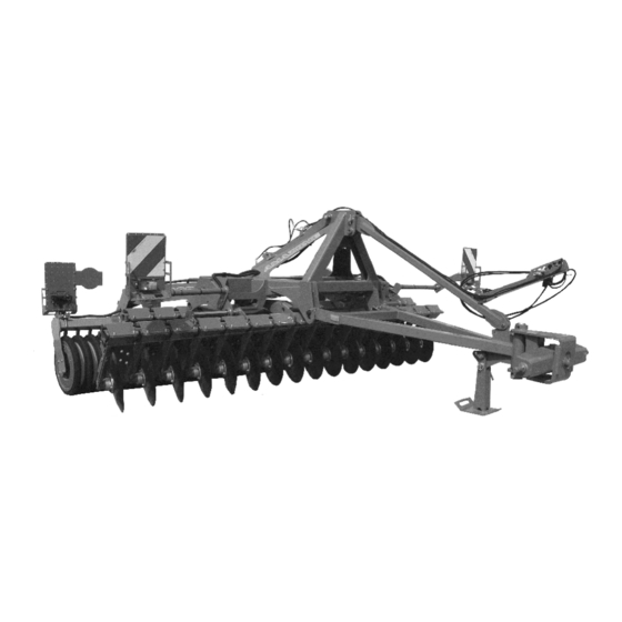
Product Description Product Description This section provides: a comprehensive overview of the implement structure the names of the individual modules and controls Read this section while standing next to the implement. This helps you to better understand the implement. Overview of implement assembly Fig. -
Page 30: Power Supply Cables Between The Tractor And Implement
Product Description Fig. 6 (1) 1st row of disks (2) 2nd row of disks (3) Wedge ring roller (4) Scraper bar for wedge ring roller (5) Hydraulic cylinder, Transport position / Working position (6) Spacer elements for depth adjustment (7) Wheel chocks in transport position Power supply cables between the tractor and implement ... -
Page 31: Transportation Equipment
Product Description Transportation equipment Fig. 7/… (1) Rear lights; brake lights; turn indicators, red reflectors (round) (2) Warning signs (square) Fig. 7 Fig. 8/… (1) 2 limiting lights; turn indicators (2) 2 warning signs (square) Fig. 8 Fig. 9 Two yellow reflective markings on the front of the machine located on the far left and right of the machine (not illustrated). -
Page 32: Intended Use
execution of inspection and maintenance work exclusive use of AMAZONE original spare parts Other uses to those specified above are prohibited and shall be con- sidered as improper. For any damage resulting from improper use: ... -
Page 33: Danger Area And Danger Points
Product Description Danger area and danger points The danger area is the area around the implement in which people can be caught by: work movements made by the implement and its tools materials or foreign objects ejected by the implement ... -
Page 34: Identification Plate And Ce Marking
Product Description Identification plate and CE marking The following diagrams show the location of the identification plate and CE marking. The identification plate shows: Serial No.: Model Approved Drawbar Load (lb) Approved Axle Load (lb) Maximum System Pressure (psi) ... -
Page 35: Tractor Requirements
Product Description 1.18-7 1.18-7 1.18-7 Working depth [mm] [30-180] [30-180] [30-180] Tractor requirements For the implement to be operated as intended, the tractor must fulfill the following requirements: Tractor engine power from 80 hp [60 kW] upwards Catros / Catros 3002-T from 105 hp [77 kW] upwards Catros / Catros... -
Page 36: Structure And Function
Structure and Function Structure and Function The following section provides information on the machine structure and the functions of the individual components. Function Fig. 11 The Catros compact disk harrow is suitable for: shallow stubble cultivation directly after harvesting ... -
Page 37: Hydraulic System Connections
Structure and Function Hydraulic system connections All hydraulic hose lines are equipped with gripping sections. Coloured markings with a code number or code letter have been ap- plied to the gripping sections in order to assign the respective hydrau- lic function to the pressure line of a tractor controller! Films are stuck on the implement for the markings that illustrate the respective hydraulic function. -
Page 38: Connecting The Hydraulic Hose Lines
Structure and Function 5.2.1 Connecting the hydraulic hose lines WARNING Risk of being crushed, cut, caught, drawn in or struck due to faulty hydraulic functions when the hydraulic hose lines are in- correctly connected! When connecting the hydraulic hose lines, observe the colored mark- ings on the hydraulic plugs. -
Page 39: Disconnecting The Hydraulic Hose Lines
Structure and Function 5.2.2 Disconnecting the hydraulic hose lines 1. Adjust the operating lever on the control unit of the tractor to float position (neutral position). 2. Unlock the hydraulic connectors from the hydraulic sockets. 3. Protect the hydraulic connectors and hydraulic connector sock- ets against contamination using the dust protection caps. -
Page 40: Two-Row Disk Harrow
The offsetting of the two disk rows, which can be coordinated via the offset slide with regard to working depth and speed. Adjustment is made with the AMAZONE Fig. 12 eccentric pins. The working intensity of the disks via the working depth. -
Page 41: Wedge Ring Roller
Structure and Function Wedge ring roller Fig. 15 The wedge ring roller (Fig. 15/1) compacts the cultivated soil in strips, assumes the depth control of the concave disks. becomes the running gear during transport. The scraper bar (Fig. 15/2) cleans between the wedge rings. Tensioned crosspiece Fig. -
Page 42: Stand
Structure and Function Stand Fig. 17/… (1) Handle (2) Pin During operation or transport: Stand fixed in raised position with pin and secured with linch pin. With implement disconnected: Stand fixed in lowered position with pin and secured with linch pin. Fig. -
Page 43: Safety Chain For Implements Without Brake System
Structure and Function Safety chain for implements without brake system Implements without a brake system or with a single-line brake system must be equipped with a safety chain in compliance with local country regulations. The safety chain must be correctly fixed to a suitable position on the tractor before transporting. -
Page 44: Commissioning
Commissioning Commissioning This section contains information about: operating your implement for the first time and how you connect the implement to your tractor. Before operating the implement for the first time the operator must have read and understood the operator’s manual. ... -
Page 45: Checking The Suitability Of The Tractor
Commissioning Checking the suitability of the tractor WARNING Danger of machinery breaking during operation; insufficient stability and insufficient tractor steering and braking power is possible when tractor is improperly used! Check the suitability of your tractor before you attach or connect the implement. - Page 46 Commissioning 6.1.1.1 Data required for the calculation Fig. 20 lb [kg] Base (empty) tractor weight See tractor operator’s manual or vehicle lb [kg] Front axle load of the base tractor documentation lb [kg] Rear axle load of the base tractor lb [kg] Front weight (if available) See front weight in technical data, or weight lb [kg] Maximum drawbar load...
- Page 47 Commissioning 6.1.1.2 Calculation of the required minimum ballasting at the front G of the tractor for V min assurance of the steering capability Enter the numeric value for the calculated minimum ballast G V min required on the front side of the tractor in the table (section 6.1.1.7).
- Page 48 Commissioning 6.1.1.7 Table Actual value according to Approved value Double approved calculation according to tractor load capacity (two operator’s manual tires) Minimum ballast front / rear [kg] Total weight [kg] [kg] Front axle load [kg] [kg] [kg] ...
-
Page 49: Requirements For Tractor Operation With Attached Implements
Commissioning 6.1.2 Requirements for tractor operation with attached implements WARNING Risk of damage during operation of components through unapproved combinations of equipment! Ensure that the: connection fittings on the tractor possess sufficient support capability for the actual drawbar load present. ... -
Page 50: Securing The Tractor / Implement Against Unintentional Start-Up And Rolling
Commissioning Securing the tractor / implement against unintentional start-up and rolling WARNING Risk of crushing, cutting, catching, being drawn in and/or knocked down when intervening in the implement through unin- tentional: lowering of the implement when it is lifted with the tractor's three-point hydraulic system and unsecured, ... -
Page 51: Connecting And Disconnecting The Implement
Connecting and Disconnecting the Implement Connecting and Disconnecting the Implement When connecting or disconnecting implements, follow the instructions given in the section "Safety instructions for the operator" page 21. WARNING Risk of crushing through unintentional starting and rolling of the tractor and implement when connecting or disconnecting the implement! Secure the tractor and implement against unintentional start-up and... -
Page 52: Connecting The Implement
Connecting and Disconnecting the Implement Connecting the implement WARNING Danger of damage during operation, insufficient stability and insufficient tractor steering and braking power when tractor is improperly used! You may only connect the implement to a tractor suitable for the purpose. - Page 53 Connecting and Disconnecting the Implement 1. Attach the ball sleeves over the lower link pins of the implement. 2. Secure the implement from unintentional disconnection using linchpins for the upper and lower link pins. 3. Direct people away from the danger area between the tractor and implement before approaching the implement with the trac- tor.
-
Page 54: Disconnecting The Implement
Connecting and Disconnecting the Implement Disconnecting the implement WARNING Risk of crushing, cutting, catching, being drawn in and/or being knocked down through insufficient stability and possible tilting of the disconnected implement! Park the implement on a horizontal space with a hard surface. When disconnecting the implement, there must always be enough space in front of the implement, so that you can align the tractor with the implement if necessary. -
Page 55: Adjustments
Adjustments Adjustments WARNING Risk of crushing, cutting, catching, being drawn in and/or being knocked down through unintentional: falling of the lifted implement using the tractor's three-point hydraulic system. falling of lifted, unsecured implement parts. starting-up and rolling of the tractor-implement combina- tion. -
Page 56: Offset Of The Disk Rows
Adjustments Offset of the disk rows The offset disk row is adjusted as necessary by means of an AMAZONE eccentric pin. For this reason there are 6 insertion holes are available (Fig. 22). 1. Move the implement backwards while in working position. -
Page 57: Working Depth Of Outside Disks
Adjustments The work pattern must be checked by viewing the cultivation horizon behind the implement: (1) Cutting edge 1st disk row (2) Cutting edge 2nd disk row Fig. 24: Correct setting of disk rows. Fig. 24 Fig. 25: Adjust 1st disk row to right and check again. -
Page 58: Scraper
Adjustments Scraper Scrapers are adjusted at the factory. Adjust the setting to the working conditions as follows: 1. Secure the tractor against unintentional starting and/or rolling away. 2. Release the tension bolts (Fig. 28/1) below the scraper. 3. Adjust the scraper in the slotted hole. 4. -
Page 59: Transportation
Transportation Transportation While transporting, follow the instructions given in the section "Safety instructions for the owner or field operations manager ", page 23. Before starting, check that the: supply lines are connected correctly lighting system for damage, function and cleanliness ... -
Page 60: Converting From Operational To Transport Position
Transportation WARNING Risk of damage during operation, insufficient stability and insuf- ficient tractor steering and braking power when tractor is im- properly used! These risks may pose serious injuries and/or death. Observe the permissible axle and drawbar loads of the tractor. WARNING Risk of falling from the implement if riding against regulations! It is prohibited to ride on the implement and/or climb on the imple-... -
Page 61: Use Of The Implement
Use of the Implement Use of the Implement When using the implement, observe the information in the sections "Warning labels and safety markings on the implement", from page 16 and "Safety instructions for operators", from page 21 Observing this information is important for your safety. WARNING Risk of damage during operation, insufficient stability and insuf- ficient tractor steering and braking power when tractor is im-... -
Page 62: Conversion From Transport To Operational Position
Use of the Implement 10.1 Conversion from transport to operational position WARNING Instruct people to leave the danger area of implement's wings before you fold or unfold the implement wings. Align the tractor and implement straight on a flat surface before folding or unfolding the implement's wings! ... -
Page 63: Use In The Field
Use of the Implement 10.2 Use in the field The lifting wing spindles of the implement near the upper link of the tractor must be adjusted so that the frame is parallel to the soil sur- face longitudinally and transversely during operation! 10.3 Headland turning When turning through a curve at the headland, the disk rows must be... -
Page 64: Cleaning, Maintenance And Repairs
Cleaning, Maintenance and Repairs Cleaning, Maintenance and Repairs WARNING Risk of crushing, cutting, catching, being drawn in and/or knocked down through unintentional: falling of the lifted implement using the tractor's three-point hydraulic system falling of lifted, unsecured implement parts ... -
Page 65: Lubricants
Cleaning, Maintenance and Repairs 11.2.1 Lubricants For lubrication work, use a lithium saponified multipurpose grease with EP additives: Company Lubricant ARAL Aralub HL2 FINA Marson L2 ESSO Beacon 2 SHELL Retinax A 11.2.2 Lubrication point overview Fig. 34 Lubrication point Interval [h] Quantity Running gear frame mount Hydraulic cylinder... -
Page 66: Service Plan - Overview
Cleaning, Maintenance and Repairs 11.3 Service plan – overview Carry out maintenance work when the first interval is reached. The times, continuous services or maintenance intervals of any third party documentation shall have priority. After first operation Servicing work Component Specialist workshop page... -
Page 67: Replacing Disks (Workshop Work)
Cleaning, Maintenance and Repairs 11.4 Replacing disks (workshop work) Minimum disk diameter: 1.2 ft [360 mm]. To replace the disks: unfold implement elevate disks secure implement against unintentional lowering 1. Release the four bolts securing the disk 2. -
Page 68: Slide Bearings Of Offset Slide (Workshop Work)
Cleaning, Maintenance and Repairs 11.5 Slide bearings of offset slide (workshop work) Replace slide bearing at approximately. 1/6 inch [4 mm] clearance. To replace the slide bearings (Fig. 38/1), lower the unfolded implement so that the slide bearings are free of tension. The disk units must touch the ground, but must not support the weight of the implement! If necessary, support the disk units! -
Page 69: Finishing Roller
Cleaning, Maintenance and Repairs 11.7 Finishing roller WARNING Inspect the roller bearings for tightness at regularly! Risk of accidents due to defective bearings! Check the bolts for tightness. Required tightening torque: 155 ft lb [210 Nm]. To connect the rollers correctly, the clamping bracket and its bolts must be installed according to Fig. -
Page 70: Hydraulic System
Replace the hydraulic hose line if it is damaged or worn. Only use AMAZONE original hydraulic hose lines. The hydraulic hose lines should not be used for longer than six years, including any storage time of maximum two years. Even... -
Page 71: 11.10.1 Hydraulic Hose Line Labeling
Cleaning, Maintenance and Repairs 11.10.1 Hydraulic hose line labeling The assembly labeling provides the following information: Fig. 42/... (1) Manufacturer's marking on the hydraulic hose line (A1HF) (2) Date of manufacture of hydraulic hose line (04 / 02 = year / month = February 2004) (3) Maximum approved operating pressure (3,045 psi [210 BAR]). -
Page 72: 11.10.4 Installation And Removal Of Hydraulic Hose Lines
11.10.4 Installation and removal of hydraulic hose lines When installing and removing hydraulic hose lines, always observe the following information: Only use AMAZONE original hydraulic hose lines. Ensure cleanliness. You must always install the hydraulic lines so that, in all states of operation: ... -
Page 73: Hydraulic Diagram
Cleaning, Maintenance and Repairs 11.12 Hydraulic diagram Fig. 43 (1) Connection of control unit – Put in working position (Hose marking 1 - yellow) (2) Connection of control unit – Put in transport position (Hose marking 2 - yellow) (3) Hydraulic cylinder (4) Locking block Catros02-T BAG0078.3 03.14... -
Page 74: Bolt Tightening Torques
Cleaning, Maintenance and Repairs 11.13 Bolt tightening torques ft lb [Nm] 10.9 12.9 18.5 [25] 25.8 [35] 30.2 [41] M 8x1 19.9 [27] 28 [38] 30.2 [41] M 10 36 [49] 51 [69] 61 [83] 16 (17) M 10x1 38 [52] 54 [73] 65 [88] M 12... - Page 75 Catros02-T BAG0078.3 03.14...
- Page 76 Postfach 51 Phone: +49 5405 501-0 D-49202 Hasbergen-Gaste Fax: +49 5405 501-234 Germany e-mail: amazone@amazone.de http:// www.amazone.de Plants: D-27794 Hude D-04249 Leipzig F-57602 Forbach Branches in England and France Manufacturers of mineral fertilizer spreaders, field sprayers, seeding implements,...
Need help?
Do you have a question about the Catros 3002-T and is the answer not in the manual?
Questions and answers