Amazone Catros 2503 Special Operating Manual
Mounted compact disc harrow
Hide thumbs
Also See for Catros 2503 Special:
- Original operating manual (74 pages) ,
- Original operating manual (82 pages)
Table of Contents
Advertisement
Quick Links
Catros 2503 Special
Catros 3003 Special
Catros 3503 Special
Catros 4003 Special
MG5533
BAG0160.4 02.19
Printed in Germany
en
Operating Manual
AMAZONE
Mounted compact disc harrow
Catros
+
2503 Special
Catros
+
3003 Special
Catros
+
3503 Special
Catros
+
4003 Special
Please read and follow this
operating manual before putting
the machine into operation.
Keep it in a safe place for
future use.
Advertisement
Table of Contents

Related Manuals for Amazone Catros 2503 Special


Summary of Contents for Amazone Catros 2503 Special
- Page 1 Operating Manual AMAZONE Catros 2503 Special Catros 2503 Special Catros 3003 Special Catros 3003 Special Catros 3503 Special Catros 3503 Special Catros 4003 Special Catros 4003 Special Mounted compact disc harrow Please read and follow this operating manual before putting MG5533 the machine into operation.
- Page 2 Reading the instruction Manual and following it should seem to be in- convenient and superfluous as it is not enough to hear from others and to realize that a machine is good, to buy it and to believe that now everything should work by itself.
- Page 3 +49 5405 501-0 E-mail: amazone@amazone.de Spare part orders Spare parts lists are freely accessible in the spare parts portal at www.amazone.de. Please send orders to your AMAZONE dealer. Formalities of the operating manual Document number: MG5533 Compilation date: 02.19 ...
- Page 4 Dear Reader We update our operating manuals regularly. Your suggestions for improvement help us to create ever more user-friendly manuals. AMAZONEN-WERKE H. DREYER GmbH & Co. KG Postfach 51 D-49202 Hasbergen Phone: +49 5405 501-0 E-mail: amazone@amazone.de Catros BAG0160.4 02.19...
-
Page 5: Table Of Contents
User information User information ..................7 Purpose of the document ......................7 Locations in the operating manual ................... 7 Diagrams used ......................... 7 General safety instructions ................. 8 Obligations and liability ......................8 Representation of safety symbols ..................10 Organisational measures ....................... 11 Safety and protection equipment ................... - Page 6 User information Tractor wheel mark eradicator ....................40 5.10 Rear harrow (optional)......................41 5.11 GreenDrill catch crop sowing unit ..................43 Commissioning ..................44 Checking the suitability of the tractor ..................45 6.1.1 Calculating the actual values for the total tractor weight, tractor axle loads and load capacities, as well as the minimum ballast ................
-
Page 7: User Information
User information User information The "User information" section supplies information on using the op- erating manual. Purpose of the document This operating manual • Describes the operation and maintenance of the machine. • Provides important information on safe and efficient handling of the machine. -
Page 8: General Safety Instructions
General safety instructions General safety instructions This section contains important information on safe operation of the machine. Obligations and liability Comply with the instructions in the operating manual Knowledge of the basic safety information and safety regulations is a basic requirement for safe handling and fault-free machine operation. Obligations of the operator The operator is obliged only to let those people work with/on the ma- chine who... - Page 9 General safety instructions Risks in handling the machine The machine has been constructed to the state-of-the art and the recognised rules of safety. However, there may be risks and re- strictions which occur when operating the machine • For the health and safety of the user or third persons, •...
-
Page 10: Representation Of Safety Symbols
General safety instructions Representation of safety symbols Safety instructions are indicated by the triangular safety symbol and the highlighted signal word. The signal word (DANGER, WARNING, CAUTION) describes the gravity of the risk and has the following sig- nificance: DANGER Indicates an immediate high risk, which will result in death or serious physical injury (loss of body parts or long term damage) if not avoided. -
Page 11: Organisational Measures
General safety instructions Organisational measures The operator must provide the necessary personal protective equip- ment, such as: • Protective glasses • Protective shoes • Protective suit • Skin protection, etc. The operation manual • Must always be kept at the place at which the machine is oper- ated. -
Page 12: User Training
General safety instructions User training Only those people who have been trained and instructed may work with/on the machine. The operator must clearly specify the responsi- bilities of the people charged with operation, maintenance and repair work. People being trained may only work with/on the machine under the supervision of an experienced person. -
Page 13: Safety Measures In Normal Operation
General safety instructions Safety measures in normal operation Only operate the machine if all the safety and protection equipment is fully functional. Check the machine at least once a day for visible damage and check the function of the safety and protection equipment. Dangers from residual energy Note that there may be residual mechanical, hydraulic, pneumatic and electrical/electronic energy at the machine. -
Page 14: Spare And Wear Parts And Aids
Immediately replace any machine parts which are not in a perfect state. Use only genuine AMAZONE spare and wear parts or the parts cleared by AMAZONEN-WERKE so that the operating permit retains its validity in accordance with national and international regulations. If... -
Page 15: Warning Pictograms And Other Signs On The Machine
General safety instructions 2.13 Warning pictograms and other signs on the machine 2.13.1 Positioning of warning pictograms and other labels Warning pictograms The following diagrams show the arrangement of the warning picto- grams on the machine. Always keep all the warning pictograms of the machine clean and in a legible state. - Page 16 General safety instructions Warning pictograms - structure Warning pictograms indicate dangers on the machine and warn against residual dangers. At these points, there are permanent or unexpected dangers. A warning pictogram consists of two fields: Field 1 is a pictogram describing the danger, surrounded by triangular safety symbol.
- Page 17 General safety instructions Order number and explanation Warning pictograms MD078 Risk of contusions for fingers or hands through accessible moving machine parts! This danger causes extremely serious injuries with the loss of body parts such as fingers or hands. Never reach into the danger area when the trac- tor engine is running with PTO shaft / hydraulic system connected.
- Page 18 General safety instructions MD097 Danger of crushing your torso in the stroke range of the three-point suspension due to the narrowing spaces when the three-point hydraulic system is actuated! This danger causes extremely serious injuries and even death. Personnel are prohibited from entering the stroke area of the three-point suspension when the three-point hydraulics are actuated.
-
Page 19: Dangers If The Safety Information Is Not Observed
General safety instructions 2.14 Dangers if the safety information is not observed Nonobservance of the safety information • Can pose both a danger to people and also to the environment and machine. • Can lead to the loss of all warranty claims. Seen individually, non-compliance with the safety information could pose the following risks: •... -
Page 20: Safety Information For Users
General safety instructions 2.16 Safety information for users WARNING Risk of being crushed, cut, caught, drawn in or struck due to insufficient traffic and operational safety! Before starting up the machine and the tractor, always check their traffic and operational safety. 2.16.1 General safety and accident prevention information •... - Page 21 General safety instructions • When coupling and uncoupling machines, move the support equipment (if available) to the appropriate position (stability). • When actuating the support equipment, there is a danger of inju- ry from contusion and cutting points! • Be particularly careful when coupling the machine to the tractor or uncoupling it from the tractor! There are contusion and cutting points in the area of the coupling point between the tractor and the machine.
- Page 22 General safety instructions Machine transportation • When using public highways, national road traffic regulations must be observed. • Before moving off, check: ο the correct connection of the supply lines ο the lighting system for damage, function and cleanliness ο the brake and hydraulic system for visible damage ο...
-
Page 23: Hydraulic System
• Replace the hydraulic hose line if it is damaged or worn. Only use AMAZONE original hydraulic hose lines. • The hydraulic hose lines should not be used for longer than six years, including any storage time of maximum two years. Even... -
Page 24: Electrical System
• Spare parts must meet at least the specified technical require- ments of AMAZONEN-WERKE! This is ensured through the use of AMAZONE original spare parts. Catros BAG0160.4 02.19... -
Page 25: Loading And Unloading
Loading and unloading Loading and unloading Loading using a lifting crane: CAUTION When loading the machine using a lifting crane, use the marked lash- ing points for lifting belts. CAUTION The minimum tensile strength of each lifting belt must be 1000 kg! The machine has 4 lashing points for lifting belts. -
Page 26: Product Description
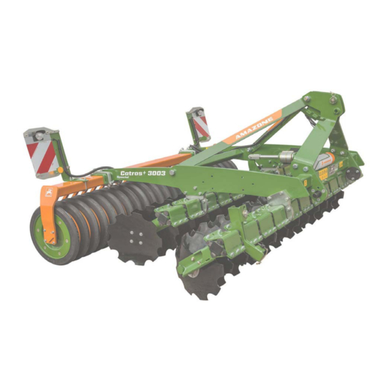
Product description Product description This section: • Provides a comprehensive overview of the machine structure. • Provides the names of the individual modules and controls. Read this section when actually at the machine. This helps you to understand the machine better. Overview of subassemblies (1) Three-point attachment (4) Trailing roller in various versions... -
Page 27: Transportation Equipment
Compliance with all the instructions in this operating manual. • Execution of inspection and maintenance work. • Exclusive use of AMAZONE original spare parts. Other uses to those specified above are forbidden and shall be con- sidered as improper. For any damage resulting from improper use: •... -
Page 28: Danger Area And Danger Points
Product description Danger area and danger points The danger area is the area around the machine in which people can be caught: • By work movements made by the machine and its tools • By materials or foreign objects ejected by the machine •... -
Page 29: Rating Plate And Ce Marking
Product description Rating plate and CE marking The following diagrams show the location of the rating plate and CE marking. The rating plate shows: • Vehicle- / machine ID no.: • Type • Basic weight kg • Permissible system pressure (bar) •... - Page 30 Product description Basic weight Catros Special 2503 3003 3503 4003 Basic machine 1100 1390 1480 Catros [kg] 1130 1430 1540 Catros 1000 Cage roller SW520 [kg] SW600 Tooth packer roller PW600 [kg] Tandem roller TW520/380 [kg] Wedge ring roller KW580 [kg] with Matrix profile KWM650...
-
Page 31: Necessary Tractor Equipment
Product description Necessary tractor equipment For the machine to be operated as intended, the tractor must fulfil the following requirements: Tractor engine power 2503 Special from 59 kW (80 PS) Catros / Catros 3003 Special from 66 kW (90 PS) Catros / Catros 3503 Special from 77 kW (105 PS) Catros / Catros... -
Page 32: Structure And Function
Structure and function Structure and function The following section provides information on the machine structure and the functions of the individual components. Function The Catros compact disc cultivator is suitable for • shallow stubble cultivation directly after threshing • seed bed preparation in spring for maize or sugar beet •... -
Page 33: Hydraulic System Connections
Structure and function Hydraulic system connections • All hydraulic hose lines are equipped with grips. Coloured markings with a code number or code letter have been applied to the gripping sections in order to assign the respective hydraulic function to the pressure line of a tractor control unit! Films are stuck on the implement for the markings that illustrate the respective hydraulic function. -
Page 34: Coupling The Hydraulic Hose Lines
Structure and function 5.2.1 Coupling the hydraulic hose lines WARNING Risk of being crushed, cut, caught, drawn in or struck due to faulty hydraulic functions when the hydraulic hose lines are connected incorrectly! When coupling the hydraulic hose lines, observe the coloured mark- ings on the hydraulic plugs. -
Page 35: Two-Row Disc Cultivator
Structure and function Two-row disc cultivator Catros disc cultivator with serrated discs and 510 mm diameter. Catros disc cultivator with smooth discs and 460 mm diameter. The concave discs are arranged offset to the direction of travel by an angle of 17° at the front and 14°... -
Page 36: Border Elements
Structure and function Border elements Levelling in the edge area is performed using the border elements. The border elements can be folded to reduce the transport width (not for Catros 2503). (1) Side disc (2) Depth adjustment (3) Pin for locking the transport and working position Catros BAG0160.4 02.19... -
Page 37: Roller
Structure and function Roller The roller takes over the depth control of the tools. • Tandem roller TW520/380 The tandem roller consists of ο the front spiral tube roller installed in the top group of holes. ο the rod roller installed in the bottom group of holes. - Page 38 Structure and function • U-profile roller UW580 → Very well suited for light soils. → Resistant to clogging and good load- bearing capacity. • Double U-profile roller DUW580 → Very well suited for light and medium soils. → Resistant to clogging and good load- bearing capacity.
-
Page 39: Three-Point Hitch Frame
Structure and function Three-point hitch frame The implement has: • Category III upper and lower link pins with locking linch pins. • 2 positions for coupling the top link Depending on the installation of the bolted lower link pin, a spread of Category 2 or 3 is reached. Front rack The front rack enables mounting of the crush- board or the tractor wheel mark eradicator. -
Page 40: Crushboard
Structure and function Crushboard The crushboard serves to level and crumble the soil. The working intensity can be adjusted mechani- cally or hydraulically. Tractor wheel mark eradicator The tractor wheel mark eradicators loosen the compacted soil behind the tractor wheels. The working depth of the tractor wheel mark eradicators can be adjusted. -
Page 41: Rear Harrow (Optional)
Structure and function 5.10 Rear harrow (optional) The rear harrow cannot be used on implements with cutting ring roller RW600 and tandem roller TW520/380. The rear harrow is used to crumble and level the soil. The working intensity can be adjusted by insert- ing the pins into different holes. - Page 42 Structure and function Harrow system 12-284 Hi For rollers: TW520/380, DUW580 Spring blade system 167 For roller: UW580 Spring clearer system142 For roller: WW580 Catros BAG0160.4 02.19...
-
Page 43: Greendrill Catch Crop Sowing Unit
Structure and function 5.11 GreenDrill catch crop sowing unit The GreenDrill catch crop sowing unit enables the sowing of fine seeds and catch crops during soil cultivation with the Catros disc cultivator. (1) GreenDrill (2) Foldable ascent (3) Bolt with linch pin for securing the foldable ascent See also the GreenDrill operating manual. -
Page 44: Commissioning
Commissioning Commissioning This section contains information • on operating your machine for the first time. • on checking how you may connect the machine to your tractor. • Before operating the machine for the first time the operator must have read and understood the operating manual. •... -
Page 45: Checking The Suitability Of The Tractor
Commissioning Checking the suitability of the tractor WARNING Danger of breaking during operation, insufficient stability and insufficient tractor steering and braking power on improper use of the tractor! • Check the suitability of your tractor before you attach or hook up the machine. - Page 46 Commissioning 6.1.1.1 Data required for the calculation [kg] Empty tractor weight See tractor operating manual or vehicle [kg] Front axle load of the empty tractor documentation [kg] Rear axle load of the empty tractor [kg] Total weight of rear-mounted machine or See technical data for machine or rear bal- rear ballast last...
- Page 47 Commissioning 6.1.1.2 Calculation of the required minimum ballasting at the front G of the tractor for V min assurance of the steering capability • − • • • Enter the numeric value for the calculated minimum ballast G V min required on the front side of the tractor, in the table (Section 6.1.1.7).
- Page 48 Commissioning 6.1.1.7 Table Actual value according to Approved value ac- Double approved calculation cording to tractor load capacity (two instruction manual tyres) Minimum ballast front / rear ≤ Total weight ≤ ≤ Front axle load ≤ ≤ Rear axle load •...
-
Page 49: Securing The Tractor / Machine Against Unintentional Start-Up And Rolling
Commissioning Securing the tractor / machine against unintentional start-up and roll- WARNING Risk of contusions, cutting, catching, drawing in and knocks when making interventions in the machine through • unintentional lowering of the machine when it is raised with the tractor's three-point hydraulic system and unsecured. •... -
Page 50: Coupling And Uncoupling The Machine
Coupling and uncoupling the machine Coupling and uncoupling the machine When coupling and uncoupling machines, follow the instructions giv- en in the section "Safety instructions for the operator" page 20. WARNING Risk of contusions from unintentional starting and rolling of the tractor and machine when coupling or uncoupling the machine! Secure the tractor and machine against unintentional start-up and rolling away before entering the danger area between the tractor and... - Page 51 Coupling and uncoupling the machine WARNING Risk of contusions, cutting, catching, drawing in and knocks when the machine unexpectedly releases from the tractor! • Use the intended equipment to connect the tractor and the ma- chine in the proper way. •...
-
Page 52: Uncoupling The Machine
Coupling and uncoupling the machine 6. From the tractor seat, couple the upper link to the top attach- ment point of the three-point attachment frame using the top link hook. → The top link hook locks automatically. 7. Perform a visual inspection to ensure that the upper and lower link hooks are correctly locked before reversing the tractor. -
Page 53: Adjustments
Adjustments Adjustments WARNING Risk of contusions, cutting, catching, drawing in and knocks through • unintentional falling of the machine raised using the trac- tor's three-point hydraulic system. • unintentional falling of raised, unsecured machine parts. • unintentional start-up and rolling of the tractor-machine combination. -
Page 54: Hydraulic Working Depth Adjustment
Adjustments Reducing the working depth → More spacer elements behind the stop wash- 1. Raise the coupled implement (unload the front spacer elements). 2. Secure the tractor against unintentional rolling. 3. Swivel the desired number of spacer ele- ments in front of the stop washer away from the setting rod. -
Page 55: Scraper
Adjustments Scraper Scrapers are adjusted at the factory. Adjust the setting to the working conditions as follows: 1. Secure the tractor against unintentional starting and unintentional rolling away. 2. Release the screw (1) below the scraper. 3. Adjust the scraper in the slotted hole. 4. -
Page 56: Adjusting The Working Depth Of The Tractor Wheel Mark Eradicators
Adjustments Manual adjustment 1. Secure the tractor against unintentional starting and unintentional rolling away. 2. Adjust the intensity using the crank and secure the crank with the linch pin. • Turning the crank towards the right: → lower intensity • Turning the crank towards the left: →... -
Page 57: Transportation
Transportation Transportation • On transportation journeys, follow the instructions given in the section "Safety instructions for the operator", page 22. • Before moving off, check: ο that the supply lines are connected correctly. ο the lighting system for damage, function and cleanliness. WARNING Risk of being crushed, cut, caught, drawn in or struck if the ma- chine is unintentionally released from its attached or hitched... -
Page 58: Conversion From Operational To Transport Position
Transportation Conversion from operational to transport position DANGER Risk of injury with overwidth transport. • Put the outer border elements into transport position! • Rear harrow (optional): before transporting the implement, install the transport safety bar. Follow the national road traffic regulations! Putting the border elements into transport position/working position •... -
Page 59: Use Of The Machine
Use of the machine Use of the machine When using the machine, observe the information in the sections • "Warning signs and other labels on the machine", from page 16 • "Safety instructions for operators", from page 20 Observing this information is important for your safety. WARNING Danger of breaking during operation, insufficient stability and insufficient tractor steering and braking power on improper use... -
Page 60: Use On The Field
Use of the machine 10.1 Use on the field The compact disc cultivator should preferably be used in float position of the tractor three-point hydraulic system. The depth guidance is carried out by the roller. During use in the field, operation is limited to raising or positioning the device at the headland The device must be adjusted at the lifting arm spindles and the top link of the tractor so that the frame is parallel to the soil surface longi-... -
Page 61: Cleaning, Maintenance And Repairs
Cleaning, maintenance and repairs Cleaning, maintenance and repairs WARNING Risk of contusions, cutting, catching, drawing in and knocks through • unintentional falling of the machine raised using the trac- tor's three-point hydraulic system. • unintentional falling of raised, unsecured machine parts. •... -
Page 62: Service Plan - Overview
Cleaning, maintenance and repairs 11.2 Service plan – overview • Carry out maintenance work when the first interval is reached. • The times, continuous services or maintenance intervals of any third party documentation shall have priority. After the first working run Servicing work Component See page... -
Page 63: Replacing The Discs (Workshop Work)
Cleaning, maintenance and repairs 11.3 Replacing the discs (Workshop work) Minimum disc diameter: 360 mm. The discs are replaced with • the machine folded out • the discs raised • the machine secured against unintentional lowering 1. Release the four screws securing the disc. 2. -
Page 64: Disc Carrier Fixture
Cleaning, maintenance and repairs 11.5 Disc carrier fixture Check the bolts for tightness. Required tightening torque: 210 Nm. 11.6 Top and lower link pins WARNING Risk of contusions, catching, and knocks when the machine unexpectedly releases from the tractor! Check the upper and lower link pins for visible damage each time you couple the machine. -
Page 65: Hydraulic System
• Replace the hydraulic hose line if it is damaged or worn. Only use AMAZONE original hydraulic hose lines. • The hydraulic hose lines should not be used for longer than six years, including any storage time of maximum two years. Even... -
Page 66: Labelling Hydraulic Hose Lines
Cleaning, maintenance and repairs 11.7.1 Labelling hydraulic hose lines The assembly labelling provides the follow- ing information: (1) Manufacturer's marking on the hydraulic hose line (A1HF) (2) Date of manufacture of hydraulic hose line (04 / 02 = year / month = February 2004) (3) Maximum approved operating pressure (210 BAR). -
Page 67: Installation And Removal Of Hydraulic Hose Lines
Installation and removal of hydraulic hose lines When installing and removing hydraulic hose lines, always observe the following information: • Only use AMAZONE original hydraulic hose lines. • Ensure cleanliness. • You must always install the hydraulic lines so that, in all states of operation: ο... -
Page 68: Hydraulics Diagram
Cleaning, maintenance and repairs 11.8 Hydraulics diagram depth adjustment Catros BAG0160.4 02.19... -
Page 69: Screw Tightening Torques
Cleaning, maintenance and repairs 11.9 Screw tightening torques 10.9 12.9 M 8x1 M 10 16 (17) M 10x1 M 12 18 (19) M 12x1,5 M 14 M 14x1,5 M 16 M 16x1,5 M 18 M 18x1,5 M 20 M 20x1,5 M 22 M 22x1,5 1050...
Need help?
Do you have a question about the Catros 2503 Special and is the answer not in the manual?
Questions and answers