
Related Manuals for Atlas Copco FLEXIROC T30 R


Summary of Contents for Atlas Copco FLEXIROC T30 R
- Page 1 FLEXIROC T30 R Operation Original instructions 2016-11-25 | No: 2969809547.1.2969824267 en-US...
-
Page 3: Table Of Contents
FlexiROC T30 R Table of Contents Table of Contents 1 Introduction ...................... 7 Safety First.......................... 7 The Purpose of this Publication .................... 7 Target Group .......................... 7 Feedback and Contact Information .................. 7 2 Product Description.................... 9 Intended Use of the Product ..................... 9 Misuse of the Product........................ 9 Main Components ........................ 10... - Page 4 FlexiROC T30 R Table of Contents 3.5.20 Stop Drilling/Rotation...................... 49 3.5.21 Display Heater ........................ 51 3.5.22 Replacing Remote Control ..................... 52 3.5.23 Using Cable to Remote Control.................... 53 4 Operation ...................... 55 Startup and Shutdown...................... 55 4.1.1 Turning ON Battery Power ..................... 55 4.1.2...
- Page 5 6.20 Check Hoses and Couplings.................... 117 6.21 Check Diesel Engine Control Panel .................. 118 6.22 Check Dust Collector...................... 118 7 Technical Data.................... 119 Weight ............................. 119 Dimensions FlexiROC T30 R -01................... 119 Dimensions FlexiROC T30 R -03................... 123 Electrical System ........................ 126 Air System .......................... 126 Hydraulic Systems ......................... 126 Performance ........................... 127...
- Page 6 FlexiROC T30 R Table of Contents 8.4.2 Assembling ROC-ANGIE...................... 133 8.4.3 Adjusting ROC-ANGIE to Zero Reading................ 133 8.4.4 Installing ROC-ANGIE ...................... 134 8.4.5 Aiming Examples........................ 135 8.4.6 Technical Data ROC-ANGIE .................... 136 Directional Instrument ...................... 137 8.5.1 Changing Hole Length, Hole Depth, and Laser Setting ............ 137 8.5.2...
-
Page 7: Introduction
1.4 Feedback and Contact Information Atlas Copco works actively with the development and continuous improvement of its prod- ucts and associated documentation. Provide your feedback on products and documenta- tion and access your local supplier under "Contact Us" at www.atlascopco.com. - Page 8 FlexiROC T30 R 1 Introduction No: 2969809547.1.2969824267 en-US...
-
Page 9: Product Description
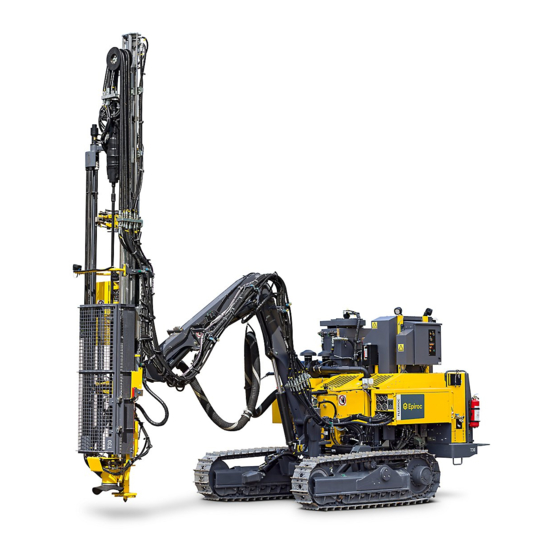
FlexiROC T30 R 2 Product Description 2 Product Description The FlexiROC T30 R has the following features and characteristics: Track-driven blasthole drill Equipped with a top hammer rock drill Powered by a diesel engine 2.1 Intended Use of the Product The rock drill rig and related equipment are designed for drilling holes in opencast mines, in quarries, and on construction sites. -
Page 10: Main Components
FlexiROC T30 R 2 Product Description 2.3 Main Components Main Components Remote control box Feed cylinder Feeder Rock drill Outer boom Inner boom Fuel tank and expansion tank Electric cabinet with diesel panel Air filter No: 2969809547.1.2969824267 en-US... -
Page 11: Wagon Frame With Track Frames
FlexiROC T30 R 2 Product Description Dust collector Boom head Drill rod support Track frame Control panel Power Pack Platform Diesel engine Winch Compressor Electric cabinet with radio unit Pressure gauge panel and operator panel Radiator 2.4 Wagon Frame with Track Frames... -
Page 12: Boom System
FlexiROC T30 R 2 Product Description 2.6 Boom System The boom system consists of: Inner and outer boom bodies Boom head Feed holder Associated hydraulic cylinders The directional valves for positioning the feed with the rock drill control the boom system. -
Page 13: Air System
2.12 Data Plate Data Plate The data plate contains the serial number (product identification number) for each individ- ual machine, and is required when: Contacting Atlas Copco for support Ordering components or kits Creating records Maintaining records No: 2969809547.1.2969824267 en-US... - Page 14 FlexiROC T30 R 2 Product Description No: 2969809547.1.2969824267 en-US...
-
Page 15: Controls And Instrument
FlexiROC T30 R 3 Controls and Instrument 3 Controls and Instrument Controls Control panel Remote control box Pressure gauge cluster and operator panel Electric cabinet with diesel panel No: 2969809547.1.2969824267 en-US... -
Page 16: Pressure Gauge Cluster
FlexiROC T30 R 3 Controls and Instrument 3.1 Pressure Gauge Cluster NOTE: The pressure gauges must be under supervision during drilling. Pressure Gauges Pump pressure, pump 1 (Percussion, tramming motors, feeder and control pressure too high, and low speed to tramming motor) -
Page 17: Operator Panel
FlexiROC T30 R 3 Controls and Instrument Operator display Rotation pressure Damper pressure (for COP 16XX) or feed pressure (for COP 12XX) ECL pressure Pressure, return oil filter 3.2 Operator Panel Control Panel Image Description Error message No: 2969809547.1.2969824267 en-US... -
Page 18: Control Panel Menus
FlexiROC T30 R 3 Controls and Instrument Image Description Percussion pressure Feed pressure Rotation Escape Enter Left Down Right 3.2.1 Control Panel Menus The operator panel provides information on diagnostics and different adjustments and set- tings. There are three main menus: Settings No: 2969809547.1.2969824267 en-US... - Page 19 FlexiROC T30 R 3 Controls and Instrument Diagnostics Options These main menus then branch out into submenus. Select the desired menu using the ar- rows and confirm with Enter. The buttons that are selectable under each menu are illumi- nated and can then be used.
-
Page 20: Settings Submenus
FlexiROC T30 R 3 Controls and Instrument Overview Menus 3.2.2 Settings Submenus The Settings main menu contains the following submenus: Under Drill Control System, active functions are visible: No: 2969809547.1.2969824267 en-US... -
Page 21: Diagnostics Submenus
FlexiROC T30 R 3 Controls and Instrument Under RPCF (Rotation Pressure Control Feed), the following settings can be made: Enabled: If the setting is changed to NO, then the RPCF function is deactivated. Start (bar): The setting for rotation pressure at which the drill feed pressure starts to drop. - Page 22 FlexiROC T30 R 3 Controls and Instrument Under Counters, engine and percussion hours can be read. Under PWM Outputs, desired and actual valve actuation can be read. If a fault is detected in the valve in question, it is indicated with the text message ERROR.
- Page 23 FlexiROC T30 R 3 Controls and Instrument Under Digital Inputs, digital inputs are located. Under Engine, there is information about fuel consumption and engine load, among other things. Unit Info CPU1 gives information about software part number, software version, and whether the CAN modules are working.
-
Page 24: Options Submenus
FlexiROC T30 R 3 Controls and Instrument NOTE: If the COMPASS HEAD shows 1999 degrees, the GPS compass lacks com- munication with the satellites. If it shows 2999 degrees, the GPS compass lacks CAN communication with the machine. 3.2.4 Options Submenus The Options main menu contains the following submenus: Under Login, settings to change the level of what can be seen can be made. -
Page 25: Shortcut Menus
FlexiROC T30 R 3 Controls and Instrument Under Load Parameters, drilling parameters can be loaded. They cannot be saved at lo- gin level OP, but require a higher login level. 3.2.5 Shortcut Menus NOTE: Shortcut menus can only be changed if the function in question is active. - Page 26 FlexiROC T30 R 3 Controls and Instrument NOTE: Only set high percussion pressure when high percussion is used. The pressure information is measured by a pressure transducer, and the lower value is the desired PWM current for Y100. Can only be used when the function is used. Adjust desired current with arrow up and down.
-
Page 27: Control Panel
FlexiROC T30 R 3 Controls and Instrument 3.3 Control Panel Control Panel Engine bay lighting Work lights, feeder Work lights, front Work lights, rear Signal Horn Circuit breaker for activating winch No: 2969809547.1.2969824267 en-US... - Page 28 FlexiROC T30 R 3 Controls and Instrument Preheating or Tramming Hydraulic oil preheating Tramming Reset button. Activated at each start (after ignition key) or when the emergency stop has been activated Starter key for diesel engine Ignition Switch for loading compressor during tramming...
-
Page 29: Diesel Engine Control Panel
FlexiROC T30 R 3 Controls and Instrument 3.4 Diesel Engine Control Panel Diesel Panel Image Description High soot content in the particulate filter. Regeneration required. Automatic regeneration blocked. High exhaust temperature. No: 2969809547.1.2969824267 en-US... -
Page 30: Remote Control
FlexiROC T30 R 3 Controls and Instrument Image Description Yellow indicator lamp for preheating the diesel engine. The lamp illuminates when preheating is activated. Green indicator lamp for compressor. Illuminates green when the compressor is loaded. Green indicator lamp for radio communication. Illuminates green when the rig is in contact with the remote control box. - Page 31 FlexiROC T30 R 3 Controls and Instrument Left-hand multi-function lever (Feed positioning and rod handling) Mode switch Positioning Drilling Tramming Tramming levers left and right Forward Neutral Forward Multifunction knob. See section Menu views. Navigation. Right-hand multi-function lever (Boom positioning and drilling) Emergency stop Stops the diesel engine (must be reset before restart).
-
Page 32: Safety Precautions Before Using Remote Control
FlexiROC T30 R 3 Controls and Instrument Winch motor Wind in Neutral Wind out Upper drill rod support Open Close Lower drill rod support Open Close Resetting hole depth Suction hood/Auto positioning Suction hood up (Drilling position)/ Auto positioning On (Positioning mode) -
Page 33: Right-Hand Multi-Function Lever
FlexiROC T30 R 3 Controls and Instrument Functions when positioning mode is selected. Sector Activity Feed tilt, front Feed tilt, rear Feed swing (left) Feed swing (right) Feed extension down Feed extension up Functions when drilling mode is selected. Sector... - Page 34 FlexiROC T30 R 3 Controls and Instrument Functions when positioning mode is selected. Sector Activity Boom lowering Boom lift Boom swing right Boom swing left Boom extension in Boom extension out Functions when drilling mode is selected. Sector Activity Rapid feed-forward...
-
Page 35: Right-Hand Multifunction Lever-Proportional Function
FlexiROC T30 R 3 Controls and Instrument Sector Activity High percussion. Break loose with deactivated au- tomatic drilling. Stop flushing air Proportional rotation speed. Only manual percus- sion. Proportional feed pressure. Proportional rotation speed. Only manual percussion. Functions during collaring... -
Page 36: Touch Buttons
FlexiROC T30 R 3 Controls and Instrument 3.5.5 Touch Buttons Symbol Function Description Indicates communication Trans- The symbol flashes during weak mit/Receive communication. Indicates whether the radio box The symbol flashes before the is controlling remote control has received the command. - Page 37 FlexiROC T30 R 3 Controls and Instrument Symbol Function Description Water mist, On or Off Track oscillation lock, On or Off Flushing air, On or Off Disengaging the damper pres- Active when the button is sure pressed and held. Applies to the COP 3060.
-
Page 38: Menu Navigation
FlexiROC T30 R 3 Controls and Instrument Symbol Function Description Signal Horn Open or close hatches Option "Silence kit" Open or close hatches Option "Silence kit" Automatic rod handling Winch On or Off Sleeve retainer On or Off 3.5.6 Menu Navigation Use the multifunction knob (A) and Escape (B) key to navigate, read, or change values in the different menus. -
Page 39: Menu For Information And Adjusting
FlexiROC T30 R 3 Controls and Instrument Button Description Function Escape Back one step in the menu struc- ture. Any changes that have been made in a menu are only confirmed when Enter is pressed first. 3.5.7 Menu for Information and Adjusting The menus show current information or provide the option for setting adjustable values. -
Page 40: Angle Indication Menu
FlexiROC T30 R 3 Controls and Instrument 3.5.8 Angle Indication Menu Upper value on left shows current tilt angle of feeder. To the right is an adjustment box where the desired tilt angle can be set. Lower value on left shows current swing position of feeder. To the right is an adjust- ment box where the desired side angle can be set. -
Page 41: Hole Depth And Hole Length Menu
FlexiROC T30 R 3 Controls and Instrument 3.5.10 Hole Depth and Hole Length Menu The upper box shows current hole length/hole depth, drill bit position, and penetration rate. Resetting with the touch button resets all values. Enter desired hole length/hole depth in the lower box. -
Page 42: Tramming Speed Menu
FlexiROC T30 R 3 Controls and Instrument 3.5.12 Tramming Speed Menu The menu for tramming speed adjustment appears when the switch is in the tramming po- sition, with tramming levers activated. Adjust tramming speed using the multifunction knob. 3.5.13 Winch Power Menu... -
Page 43: Feed Pressure Menu
FlexiROC T30 R 3 Controls and Instrument The menu for winch force adjustment appears when the switch is in the tramming position, with the touch button for Winch activated. Adjust winch force using the multifunction knob. 3.5.14 Feed Pressure Menu Once forward feed is activated, the feed pressure can be adjusted with the multifunction knob. - Page 44 FlexiROC T30 R 3 Controls and Instrument Each lever movement is shown with the interval 0 - 100. Each lever movement is shown with the interval 0 - 100. Testing the circuit breakers: The white indication in the center of the symbol moves up or down when testing circuit breakers, and indicates correct function.
-
Page 45: Error Messages
The figure 0 (A) gives an indication that there is no error mes- sage and the remote control works normally. If 0 has changed to another figure, then the Atlas Copco service organization must be informed for troubleshooting. No: 2969809547.1.2969824267 en-US... - Page 46 FlexiROC T30 R 3 Controls and Instrument Lever Fault The message is shown during engagement if the levers are not in start position. Release the levers for the message to disappear. The message is shown in the event of a lever fault. Communication is disconnected.
- Page 47 FlexiROC T30 R 3 Controls and Instrument Communication Fault The message is shown when radio communication is interrupted. Approach the machine for automatic reconnection. NOTE: The blue indicator lamp on the remote control flashes when communication is weak. Button Fault The message is shown if the wrong button or button combination is pushed when the remote control is started.
- Page 48 FlexiROC T30 R 3 Controls and Instrument The message is shown in the event of a fault in the button. Go to test mode to check the buttons. Inclination Error The message is shown in the event of unpermitted inclination of the remote control.
-
Page 49: Timeout Function
FlexiROC T30 R 3 Controls and Instrument If the error message remains after restart, contact the Atlas Copco service or- ganization. 3.5.17 Timeout Function The remote control has a timeout function. When the remote control has not been activated , Enter key or for 15 seconds the levers become inactive. - Page 50 FlexiROC T30 R 3 Controls and Instrument Stop Drilling/Rotation Function in Adjustment Mode When adjusting the angle of the feeder with the mode switch (B) in position drilling (2), the mode switch must be changed to position positioning (1). With continued drilling with the mode switch in position positioning, the left multi-function lever (A) and the right multi-func- tion lever (E) deactivates after 5 seconds of inactivity.
-
Page 51: Display Heater
FlexiROC T30 R 3 Controls and Instrument 3.5.21 Display Heater Display Heater in Operation If the temperature falls below approximately -9 °C, the display heater is switched on auto- matically. The symbol (A) is shown in the display. The heater is also switched off automati- cally around approximately 0 °C. -
Page 52: Replacing Remote Control
FlexiROC T30 R 3 Controls and Instrument No Display Heater 3.5.22 Replacing Remote Control Use the learn link routine for replacing the remote control. Learn link connects transmitter (rig) with receiver (remote control). After the procedure the rig addresses to the new re- mote control. -
Page 53: Using Cable To Remote Control
FlexiROC T30 R 3 Controls and Instrument è Now the transfer of data starts. The transfer is complete when the following im- age is shown on the display: Switch off the remote control with the emergency stop. Switch off the rig control system. - Page 54 FlexiROC T30 R 3 Controls and Instrument Activate the remote control as usual. NOTE: When using the cable make sure that the machine does not run over the cable! No: 2969809547.1.2969824267 en-US...
-
Page 55: Operation
FlexiROC T30 R 4 Operation 4 Operation 4.1 Startup and Shutdown 4.1.1 Turning ON Battery Power Precondition p Daily maintenance has been carried out. Turn the battery isolation switch a quarter of a turn clockwise until the handle stops. 4.1.2 Turning OFF Battery Power The battery isolation switch must be turned off once the diesel engine is shut down after finishing work, or before a period of long-term storage. -
Page 56: Activating Remote Control
FlexiROC T30 R 4 Operation 4.1.3 Activating Remote Control WARNING Accidental Operation Accidental operation can cause serious injury or damage property. The operator must have a clear line of sight when working with a remotely operated machine. Before operating the machine, always check that the controls are correctly adjusted. - Page 57 FlexiROC T30 R 4 Operation Push the reset-button (H). Activate the remote control with touch button Turn the mode switch (B) on the remote control to position (3) tramming. Check that active drill stop (F) is not activated. Establish radio communication by pressing touch button...
-
Page 58: Starting Diesel Engine
FlexiROC T30 R 4 Operation 4.1.4 Starting Diesel Engine NOTE: Monitor pressure gauges and display for diesel engine when in operation. Activate the remote control. Start the diesel engine by pressing the touch button NOTE: If the rig has a cold starting kit: During cold starting the hy- draulic pumps are unloaded when the engine is started. -
Page 59: Stopping Diesel Engine
FlexiROC T30 R 4 Operation There are three different regeneration modes: Automatic, Blocked, and Forced. In the op- erator panel, in the Settings menu, there is the Engine submenu, where the choice can be made between blocked or forced regeneration. - Page 60 FlexiROC T30 R 4 Operation Stop the diesel engine by pressing touch button Deactivate the remote control by pressing the active drill rig stop (F) on the remote control. Turn the ignition key (J) to OFF position (2) on the control panel.
-
Page 61: Tramming/Driving
FlexiROC T30 R 4 Operation NOTE: If the main power switch is turned off too early, then there is a risk that the saved engine parameters are lost. 4.2 Tramming/Driving 4.2.1 Safety Precautions Before Tramming WARNING Tipping Risk The tipping over of a machine can cause serious injury or death. -
Page 62: Preparations Before Tramming
FlexiROC T30 R 4 Operation WARNING Accidental Operation Accidental operation can cause serious injury or damage property. The operator must have a clear line of sight when working with a remotely operated machine. Before operating the machine, always check that the controls are correctly adjusted. - Page 63 FlexiROC T30 R 4 Operation Filling Fuel Manually WARNING Burning Hazard Hot engine and components can cause serious personal injury. Shut off the engine during all maintenance work. Be careful when draining hot oil and fluids. Use personal protective gear.
- Page 64 FlexiROC T30 R 4 Operation Filling DEF Tank WARNING Empty DEF Tank There is a risk of damage to the equipment if the engine is operated with empty DEF tank. The machine can be switched off and only personnel from Cummins staff can clear the fault code generated.
-
Page 65: Basic Tramming
FlexiROC T30 R 4 Operation Loosen the radiator cap (A) to the stop position, release the pressure in the cooling system and only then remove the cap. Add coolant until the level is between the upper and the lower mark (B). - Page 66 FlexiROC T30 R 4 Operation Position the feeder against the feed support (T) with multi-function levers (A) and (E). Raise the hydraulic jack. Switch (K), position (1). Open the track oscillation lock with touch button Select tramming speed depending on terrain characteristics. Touch button NOTE: Low tramming speed gives the highest traction and con- versely.
-
Page 67: Tramming On Level Ground
FlexiROC T30 R 4 Operation NOTE: A horn sounds when the drill rig reverses. NOTE: To operate one crawler track while the other is stationary, the tracks are subjected to unnecessary stresses and must there- fore be avoided. 4.2.4 Tramming on Level Ground Correct and Incorrect Position when Tramming on Level Ground 4.2.5 Tramming Uphill... -
Page 68: Tramming Downhill
FlexiROC T30 R 4 Operation 4.2.6 Tramming Downhill Correct and Incorrect Position for Tramming Downhill 4.2.7 Tramming Across Slopes WARNING Increased Risk of Sliding Can cause serious injury or death Be aware of that the risk of sliding is highest when tramming across a slope. -
Page 69: Safety Precautions Before Using Winch
FlexiROC T30 R 4 Operation 4.2.8 Safety Precautions Before Using Winch WARNING Risk of Moving Parts Can cause serious personal injury and damage to property. Ensure that unauthorized personnel are outside of the working area. Never use the winch with less than four turns remaining on the winch drum... -
Page 70: Checking Before Using The Winch
FlexiROC T30 R 4 Operation The machine must be switched off during anchoring or adjustment of the cable. A damaged cable must always be replaced. It is of the utmost importance that the cable is correctly fitted in the winch eye. It must be... -
Page 71: Tramming Up Inclines
FlexiROC T30 R 4 Operation Disengage the winch drum by lifting and turning the disengagement lever (1) a quar- ter-turn to a locked position. Pull out the wire and fasten the eye to the anchor point. Lift and turn back the engagement lever. Try turning the drum by hand to check that it is engaged. -
Page 72: Tramming Down Inclines
FlexiROC T30 R 4 Operation Set the winch pressure regulator (R106) to the desired pressure. Multifunction knob (D). Activate the winch circuit by setting the circuit breaker (F) on the control panel to posi- tion (1). Reverse up the incline using the tramming levers (C), and make sure that the wire is kept taut constantly. -
Page 73: Checking After Tramming
FlexiROC T30 R 4 Operation Reduce the winch cable pressure gradually until the drill rig can be driven smoothly down the incline with a suitable counterbalance from the winch. Make sure that the cable remains taut constantly. NOTE: The winch wire is always retracted on activation or tram- ming. -
Page 74: Positioning
FlexiROC T30 R 4 Operation 4.3 Positioning 4.3.1 System Settings GPS Compass Activation If the rig is equipped with a GPS compass, it is activated on machine start-up. NOTE: Make sure that the antennas are free from snow 4.3.2 Positioning Machine... -
Page 75: Drill System Positioning
FlexiROC T30 R 4 Operation Correct and Incorrect Uphill Setup Downhill Setup Position the machine as close to horizontal as possible. Correct and Incorrect Downhill Setup Setup Across Slopes WARNING Increased Risk of Slipping Can cause serious injury or death Be aware of that the risk of slipping is highest when setting up the rig across a slope. -
Page 76: Drilling
FlexiROC T30 R 4 Operation Hold the hole depth reset button for five seconds. è The blasting direction is now locked and the angles in the display are locked even though the aiming device is moved. NOTE: If the angles change when turning the aiming device, the GPS compass does not work. - Page 77 FlexiROC T30 R 4 Operation Operate the rod handling arms out from drill center. Left-hand multi-function lever (A) sector (A). Rapid feed the rock drill to its lower position. Right-hand multi-function lever (E) sector (A). No: 2969809547.1.2969824267 en-US...
- Page 78 FlexiROC T30 R 4 Operation Position the feed beam to horizontal position. Open the drill rod support (switch M and N). Move the drill rod in through the drill rod support and then close (switch 12 and 13) the drill rod support.
-
Page 79: Setting Up For Drilling
FlexiROC T30 R 4 Operation Apply hard grip by moving the right-hand multi-function lever to sector (C). Fully unthread the shank adapter from the drill rods. Right-hand multi-function lever sector (H). Reposition the drill rods in the carousel by moving the left-hand multi-function lever to sector (A) 4.4.3 Setting Up for Drilling... - Page 80 FlexiROC T30 R 4 Operation Make sure that the track oscillation lock is open. Touch button Set the drill rig in the horizontal position with the controls for track oscillation (G). Close the track oscillation lock Lower the jack to the ground (K).
-
Page 81: Preparing For Drilling
FlexiROC T30 R 4 Operation 4.4.4 Preparing for Drilling Put mode switch (B) in drilling position (2). Enable the sleeve retainer with touch button if a drill rods with loose sleeve is used. Position the drill rods into drill center with the left multi-function lever (A). -
Page 82: Drilling Hole
FlexiROC T30 R 4 Operation Open the rod grippers by turning and moving the left multi-function lever to section (A). 4.4.5 Drilling Hole Set the mode switch (B) in drilling position . The compressor is loaded automati- cally. Check that the track oscillation cylinders are locked. Touch button Check that the dust collector is activated. -
Page 83: Stop Drilling
FlexiROC T30 R 4 Operation Start drill feed. Right multi-function lever forward through sector (F). Low percussion is activated by turning the right multi-function lever counterclockwise and holding it turned for more than 0.5 second. NOTE: Use the drilling lever intermittently through sector (F) until solid rock is reached. -
Page 84: Feed Drilling Manually
FlexiROC T30 R 4 Operation Turn the right multi-function lever (E) counterclockwise when in low percussion, flush air on. Turn the right multi-function lever clockwise when in high percussion, flush air on. Move the right multi-function lever to sector (E) to disengage all operating functions (including flushing air). -
Page 85: Drilling Automatically
FlexiROC T30 R 4 Operation NOTE: After 5 seconds, the positioning functions will be deactivated and only percus- sion stop will work. To resume drilling, reset the mode switch to drilling position or press the multifunction knob (D). 4.4.9 Drilling Automatically Set the mode switch (B) in drilling position Check that the dust collector is activated. - Page 86 FlexiROC T30 R 4 Operation Check that the switch for flushing air is in the ON position. Flushing air starts at the same time as percussion is activated. Touch button Lower the rock drill until the drill bit is pressing lightly against the ground. Right multi- function lever (E), position (3).
-
Page 87: Loosening Manually
FlexiROC T30 R 4 Operation Switch up to high feed pressure and percussion pressure. Right multi-function lever through sector (D.F.L). Cease drilling by: Turning the right multi-function lever (E) counterclockwise when in low percus- sion, flush air on. Turning the right multi-function lever clockwise when in high percussion, flush air 4.4.10 Loosening Manually... -
Page 88: Loosening Automatically
FlexiROC T30 R 4 Operation 4.4.11 Loosening Automatically Select the settings in the operator panel. 4.4.12 Adding Extension Rods WARNING Accidental Operation Accidental operation can cause serious injury or damage property. The operator must have a clear line of sight when working with a remotely operated machine. -
Page 89: Adding Extension Rods With Rhs
FlexiROC T30 R 4 Operation Open the drill rod supports with circuit breakers (M) and (N). 4.4.13 Adding Extension Rods with RHS Precondition Make sure that the upper drill rod support (for locking the sleeve) is closed. (See sec- tion on controls, upper drill rod support switch.) Fully unthread the shank adapter from the drill sleeve. -
Page 90: Adding Extension Rods With Ras
FlexiROC T30 R 4 Operation Move left multi-function lever to sector (C) to move the drill rod out from the carousel to drill center. Move left multi-function lever to sector (C) to obtain hard grip. Move right multi-function lever) to sector (G) to thread the drill rods into the rock drill. - Page 91 FlexiROC T30 R 4 Operation Lock the coupling sleeve, close the drill rod support. Move the right multi-function lever (E) into threading position (H) to disconnect the rock drill from the drill rods. Move the right multi-function lever into position (C) to move the rock drill back.
-
Page 92: Unthreading And Extracting
FlexiROC T30 R 4 Operation Open the drill rod supports with circuit breakers (M) and (N). 4.4.15 Unthreading and Extracting WARNING Accidental Operation Accidental operation can cause serious injury or damage property. The operator must have a clear line of sight when working with a remotely operated machine. - Page 93 FlexiROC T30 R 4 Operation Move left multi-function lever (1) to sector (C) to move the rod handling arms into drill center. Turn the left-hand multi-function lever (1) to neutral position to obtain hard grip. Hold the left-hand multi-function lever in position (C).
-
Page 94: Unthreading And Extracting With Ras
FlexiROC T30 R 4 Operation Move right multi-function lever in position (A) to rapid-feed the rock drill to retrieve the next drill rod. Move right multi-function lever to sector (G) to thread in the next drill rod. 4.4.16 Unthreading and Extracting with RAS Precondition p Knock loose the joints before extraction. -
Page 95: Adjusting Water Flow For Drilling With Water Mist
FlexiROC T30 R 4 Operation 4.4.17 Adjusting Water Flow for Drilling with Water Mist The flow of water in the flushing air must be sufficient to prevent dust during collaring and drilling. Normally, a greater flow of water is required at the start of a hole. -
Page 96: Replace Drill Bit
FlexiROC T30 R 4 Operation Check point Inspection Instructions Dust collector (DCT) Suction ability and filter cleaning In the event of dust build-up: Check the filter in the filter holder, the suction hose and the drill-steel support gasket. If water flushes out of the hole the dust collector must be switched off. -
Page 97: In Case Of Breakdown Or Incident
FlexiROC T30 R 4 Operation NOTICE High Impact Percussion Risk of damage to drill Never start percussion with the drill bit in mid-air. Operate the feeder until the dowel is approximately 10 cm from the rock. Make sure that the rotation lever is in neutral position. - Page 98 FlexiROC T30 R 4 Operation Difficulties in Loosening the Coupling Sleeve The best method of loosening the coupling sleeve is to “drill” the last few centimetres with- out feed pressure and rotation, leaving percussion active for a few seconds to break the coupling sleeve.
-
Page 99: Transport
FlexiROC T30 R 5 Transport 5 Transport 5.1 Preparations Before Hoisting WARNING Risk of Crushing Crushing can cause serious personal injury or death. Use extreme caution when slinging and hoisting heavy objects. Hoisting must take place at the center of gravity. -
Page 100: Hoisting Drill Rig
FlexiROC T30 R 5 Transport The articulation lock must be installed in locked position before loading the machine onto the transport vehicle. 5.3 Hoisting Drill Rig WARNING Suspended Load Suspended load can cause serious personal injury and property damages. Do not approach a suspended load. -
Page 101: Before Transporting Loaded Drill Rig
FlexiROC T30 R 5 Transport 5.4 Before Transporting Loaded Drill Rig WARNING Tipping Risk The tipping over of a machine can cause serious injury or death. Lock the track oscillation before hoisting the machine. Adapt transportation equipment to the dimensions and weight of the machine. -
Page 102: Towing
FlexiROC T30 R 5 Transport 5.5 Towing WARNING Moving Parts May cause serious personal injury Place a wedge under both of the track frames before disengaging the traction gears CAUTION Low Oil Level in Traction Gears There is a risk of damage if the machine is towed with low oil level in the traction gears. -
Page 103: Towing Crawler
FlexiROC T30 R 5 Transport Carrier 5.5.1 Towing Crawler Before the machine can be towed, the traction gear on both track frames must be disen- gaged. Precondition p The track frames must be clean and free of all dirt and mud before the transmission cover plate is removed. - Page 104 FlexiROC T30 R 5 Transport Refit the O-ring (D) and the cylinder barrel (E). Secure the cover plate (B) in position again using the four countersunk screws. Repeat the procedure for the other track frame. The machine can now be towed.
-
Page 105: Daily Maintenance
FlexiROC T30 R 6 Daily Maintenance 6 Daily Maintenance 6.1 Maintenance table Maintenance Task Calendar Time Wash Machine Externally Daily Check Condition of Signs Daily Check Lubricant Tank Level Daily Check Fire Extinguishers Daily Check Emergency Stops and Work Lights... -
Page 106: Visual Check
FlexiROC T30 R 6 Daily Maintenance WARNING High-Pressure Cleaning High-Pressure Cleaning using compressed air, water jets, or steam jets can cause per- sonal injury. Make sure that appropriate protective clothing is worn to protect eyes and exposed parts of the body. - Page 107 FlexiROC T30 R 6 Daily Maintenance Checkpoints Cylinder brackets Feed wire with attachments Rock drill with cradle Feed holder with brackets Boom Boom bracket with pin Boom head Track frames with attachments Operator platform with attachments Winch with brackets Winch...
-
Page 108: Wash Machine Externally
FlexiROC T30 R 6 Daily Maintenance Jack All emergency stops Checkpoints Remote Control Rubber bellows on levers and switches Seals on switches and knobs The joint between the upper and lower halves of the remote control must be tightened. The remote control must not be cracked 6.4 Wash Machine Externally... -
Page 109: Check Lubricant Tank Level
FlexiROC T30 R 6 Daily Maintenance 6.6 Check Lubricant Tank Level NOTE: Bleeding of the lubrication system is necessary if all the oil is drained out of it. Precondition p The level must not be below 40 mm (1.6"). Check the tank and connections for signs of leakage. -
Page 110: Check Emergency Stops And Work Lights
FlexiROC T30 R 6 Daily Maintenance 6.8 Check Emergency Stops and Work Lights NOTE: Check each emergency stop button individually. The previous emergency stop must be reset before checking the next emergency stop. The emergency stop buttons and wires must be checked before each shift and after tramming. -
Page 111: Check Hydraulic Oil Level
FlexiROC T30 R 6 Daily Maintenance Precondition p The coolant level must be checked when the diesel engine is cold. Loosen the radiator cap (A) to the stop position, release the pressure in the cooling system and only then remove the radiator cap. The expansion tank is on the roof of the machine. -
Page 112: Check Hydraulic Oil Filter
Check to see if the needle on the pressure gauge Pressure in the return oil filter (B) is in the red zone. If so, the filter must be changed. Contact Atlas Copco. NOTE: The pressure gauge (B) Pressure in the return oil filter is only reliable when the oil has reached a temperature of at least 40 °C (104 °F) -
Page 113: Check Engine Oil Level
FlexiROC T30 R 6 Daily Maintenance Check for signs of leakage on the traction gears (B). Check for signs of leakage on the carrier roller (C). Check for signs of leakage on the track rollers (D). Visually inspect the tension on the crawler tracks (E). -
Page 114: Drain Water Condensation From Preliminary Fuel Filter
FlexiROC T30 R 6 Daily Maintenance Check that the oil level is between the upper and lower mark on the dipstick (A). Fill oil through the filler cap (B) if necessary. NOTE: Only use engine oil that the engine manufacturer approves for engine and type of operation. -
Page 115: Check Def Fluid Level
FlexiROC T30 R 6 Daily Maintenance 6.15 Check DEF Fluid Level Check the DEF fluid level (A). Top up if necessary. 6.16 Check Compressor Oil Level Precondition p The machine is parked on a flat and leveled surface. Switch off the machine and allow the oil level to settle for at least five minutes. -
Page 116: Check Limit Sensors
FlexiROC T30 R 6 Daily Maintenance 6.17 Check Limit Sensors Check function while drilling. Check that the cradle is level with each limit sensor (A) as it stops. No: 2969809547.1.2969824267 en-US... -
Page 117: Check Winch
FlexiROC T30 R 6 Daily Maintenance 6.18 Check Winch Check for damage, unwinding, wear, and corrosion on the winch cable (A). Check for damage, cracks, and wear on the hook (B) and check that it is properly mounted. 6.19 Check Remote Control Make sure none of the rubber bellows on switches and levers are damaged 6.20 Check Hoses and Couplings... -
Page 118: Check Diesel Engine Control Panel
FlexiROC T30 R 6 Daily Maintenance 6.21 Check Diesel Engine Control Panel Check that no fault indicator lamp comes on the diesel panel. In the event of a fault in- dication, stop the rig and rectify the fault. 6.22 Check Dust Collector Check the filter in the filter holder, the suction hose, and the drill rod support drill gas- ket if there is dust formation. -
Page 119: Technical Data
Weight (standard equipped without drill rods and 9 500 kg (20 950 Ibs) optional equipment) Winch 280 kg (617 Ibs) 7.2 Dimensions FlexiROC T30 R -01 3.6 m (11 ft 10 inches) 10.1 m (33 ft 2 inches) No: 2969809547.1.2969824267 en-US... - Page 120 FlexiROC T30 R 7 Technical Data 2.9 m (9 ft 7 inches) 2.8 m (9 ft 3 inches) 4.2 m (13 ft 10 inches) 7.3 m (23 ft 12 inches) 2.5 m (7 ft 11 inches) 0.4 m (1 ft 4 inches)
- Page 121 FlexiROC T30 R 7 Technical Data 2.3 m (7 ft 7 inches) 4.0 m (13 ft 2 inches) 7 m² 1.7 m (5 ft 7 inches) 4.0 m (13 ft 2 inches) No: 2969809547.1.2969824267 en-US...
- Page 122 FlexiROC T30 R 7 Technical Data 45° 50° No: 2969809547.1.2969824267 en-US...
-
Page 123: Dimensions Flexiroc T30 R -03
FlexiROC T30 R 7 Technical Data 7.3 Dimensions FlexiROC T30 R -03 2.9 m (9 ft 7 inches) 9.2 m (30 ft 3 inches) 2.9 m (9 ft 7 inches) 2.8 m (9 ft 3 inches) 4.2 m (13 ft 10 inches) 6.2 m (20 ft 5 inches) - Page 124 FlexiROC T30 R 7 Technical Data 2.5 m (8 ft 3 inches) 0.4 m (1 ft 4 inches) 2.6 m (8 ft 7 inches) 5.3 m (17 ft 5 inches) 15 m² No: 2969809547.1.2969824267 en-US...
- Page 125 FlexiROC T30 R 7 Technical Data 3.7 m (12 ft 2 inches) 4.3 m (14 ft 2 inches) 13° 50° No: 2969809547.1.2969824267 en-US...
-
Page 126: Electrical System
24 V/70W Alternator Voltage 24 V/70A 7.5 Air System Description Data FlexiROC T30 R -01 Compressor: C111 Maximum working pressure 8.5 bar Free air delivery at 8.5 bar 95 l/s FlexiROC T30 R -01 Compressor: C111 Maximum working pressure 8.5 bar Free air delivery at 8.5 bar... -
Page 127: Performance
NOTE: Stability is specified regarding CE standards. CE standards stipulate that a winch must be used when a machine is operating on an inclination steeper than 20 de- grees. FlexiROC T30 R -01 Data Inclination angles - tramming Downward or upward, maximum 20º/19º... -
Page 128: Capacities
FlexiROC T30 R 7 Technical Data FlexiROC T30 R -03 Data Inclination angles - tramming Downward or upward, maximum 20º/19º without winch Downward or upward, maximum 30º/30º with winch Laterally, maximum 20º/20º Inclination angles for drill rig Longitudinally, maximum (up- 20º/20º... -
Page 129: Options
FlexiROC T30 R 8 Options 8 Options 8.1 Filling Fuel Using Electric Fuel Filling System Precondition p Hose and filter are clean. Connect the attached hose to the fuel source. Move switch (B) to the ON position. Press switch (A) to start filling. -
Page 130: Thread Lubrication System
FlexiROC T30 R 8 Options è The electric filler pump stops automatically when the fuel tank is full or if the source of the fuel runs out. 8.2 Thread Lubrication System Lubrication tank Pump No: 2969809547.1.2969824267 en-US... -
Page 131: Operation Of Thread Lubrication System
FlexiROC T30 R 8 Options Brushes Drill rod threads are lubricated using two brushes (C) attached on the RHS carousel lower bracket. Lubricant comes from a pump (B) placed in a lubrication tank (A) at the front of the chassis frame. The pump works on compressed air from the drill rig compressor. The pump can be activated manually or automatically. -
Page 132: Roc-Angie
FlexiROC T30 R 8 Options Description Data Power Supply 12–28 V DC Current usage 0.04 A Operating temperature -20°C - +50°C Enclosing IP65 Angle measurement Measurement range 2 * 20º Measurement accuracy 0.5º 8.4 ROC-ANGIE NOTE: It is important to aim ROC-ANGIE in the blasting direction or parallel with the direction of the drill hole. -
Page 133: Preparing For Assembly Roc-Angie
FlexiROC T30 R 8 Options 8.4.1 Preparing for Assembly ROC-ANGIE Set the feed in a vertical position with the aid of a spirit level. Adjust forward and rear- ward for a precise vertical reading. Adjust left and right for a precise vertical reading. -
Page 134: Installing Roc-Angie
FlexiROC T30 R 8 Options Loosen and retighten all bolts by hand. Look at the upper scale and adjust the left and right bolts (A) to an exact zero reading on the (C) upper scale. Tighten the left and right bolts by hand. -
Page 135: Aiming Examples
FlexiROC T30 R 8 Options Adjust the feeder to the correct angle. Start drilling. 8.4.5 Aiming Examples Two different ways of aiming ROC-ANGIE are described here. In the first example, the aiming point is in line with the blasting direction. -
Page 136: Technical Data Roc-Angie
FlexiROC T30 R 8 Options NOTE: The aiming point must be at a distance of at least 100 m. 8.4.6 Technical Data ROC-ANGIE Description Data Measurement range 20° Precision 9.2° Weight, including bracket 5.0 kg Dimensions: Width 130 mm Height... -
Page 137: Directional Instrument
FlexiROC T30 R 8 Options 8.5 Directional Instrument Drill aim device Sensors To control drilling length and penetration rate, the system is equipped with a drilled length sensor. This is installed on the upper sheave and is connected to the display together with other components in the system. - Page 138 FlexiROC T30 R 8 Options Press Enter to open the submenus under Settings. Press arrow right to access the Angle Indication menu and press Enter to open the menu. Press Enter to open the menu. Press Enter once again to be able to change the values in the menu.
-
Page 139: Activating Or Inactivating Hole Angle, Hole Depth, And Laser Equipment
FlexiROC T30 R 8 Options Browse with the left and right arrows to change the values, and the up and down ar- rows to move between the settings. Save the changed value by pressing Enter. Go back out of the menus using the ESC key. - Page 140 FlexiROC T30 R 8 Options No: 2969809547.1.2969824267 en-US...
- Page 141 8 Options No: 2969809547.1.2969824267 en-US...
- Page 142 FlexiROC T30 R 8 Options No: 2969809547.1.2969824267 en-US...
- Page 143 8 Options No: 2969809547.1.2969824267 en-US...
- Page 144 www.atlascopco.com...
Need help?
Do you have a question about the FLEXIROC T30 R and is the answer not in the manual?
Questions and answers