Sign In
Upload
Download
Table of Contents
Contents
Add to my manuals
Delete from my manuals
Share
URL of this page:
HTML Link:
Bookmark this page
Add
Manual will be automatically added to "My Manuals"
Print this page
×
Bookmark added
×
Added to my manuals
Manuals
Brands
Atlas Copco Manuals
Construction Equipment
SmartROC T45
Safety manual
Atlas Copco SmartROC T45 Safety Manual
Rock drills
Hide thumbs
1
2
Table Of Contents
3
4
5
6
7
8
9
10
11
12
13
14
15
16
17
18
19
20
21
22
23
24
25
26
27
28
29
30
31
32
33
34
35
36
37
38
39
40
41
42
43
44
45
46
47
48
page
of
48
Go
/
48
Contents
Table of Contents
Bookmarks
Table of Contents
Table of Contents
1 Introduction
The Purpose of the Safety Manual
Target Group
Safety Messages in Publications
Feedback and Contact Information
2 Product Liability
3 Risks and Hazards
Stored Energy Hazard
Burn Hazard
Entanglement and Shearing Hazard
Crushing Hazard
Tipping Hazard
Scalding Hazard
Cablebreak Hazard
Pressurized Systems Hazard
Hazard Zone
Work Requiring Special Authorization
4 Safety Precautions
General Safety Guidelines
Personal Protection
Safety During Lifting, Installing and Connecting
Safety Precautions During Tramming
Safety Precautions During Operation
Safety Precautions During Service and Maintenance
Safety Guidelines, Working with Pressurized Components
Safety Guidelines, Working with Compressor
5 Safety Functions
Emergency Stop
Location of Emergency Stop
Resetting the Emergency Stop
Protective Guard
FOPS and ROPS
Fire Fighting Equipment
Fire Readiness
Fire Fighting System
Description of Fire Extinguishers
Location of Fire Extinguishers
In Case of Fire Fire Extinguisher
Emergency Exit
6 Warning Signals
Warning Beacon
Warning Beacon Automatic Systems
Signal Horn Button Location
7 Noise and Vibration
Noise Levels and Vibration Values
Declared Values
Causes of High Noise Levels
Effects of Noise
Noise Reduction Factors
Noise Combined with Other Risk Factors
Factors Affecting Whole Body Vibration
Vibration Reduction
8 Signs
General Guidelines
Warning Signs
Mandatory Action Signs
Prohibition Signs
Fire Equipment Signs
Evacuation Route Sign
Information Signs
Data Plate Contents
Signs for Ordering Spare Parts
9 Stability
Spirit Level
10 Environmental Protection
Environmental Guidelines
Oils and Greases
Fuel Spill
Exhaust Gases
Handling of Spills and Waste During Maintenance
Enduser Responsibility During Disposal
Advertisement
Quick Links
1
The Purpose of the Safety Manual
2
Oils and Greases
Download this manual
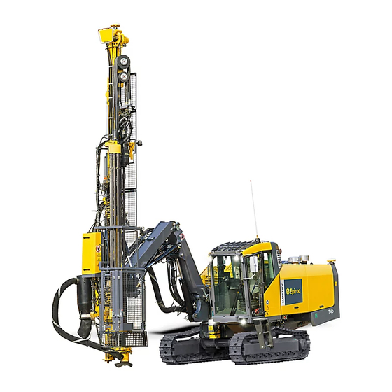
Atlas Copco Rock Drills
SmartROC T45/C50
Safety
Original instructions
© 2015 Atlas Copco AB
20150428 | No: 153375115.3.18014399362287499 enUS
Table of
Contents
Previous
Page
Next
Page
1
2
3
4
5
Advertisement
Table of Contents
Need help?
Do you have a question about the SmartROC T45 and is the answer not in the manual?
Ask a question
Questions and answers
Related Manuals for Atlas Copco SmartROC T45
Construction Equipment Atlas Copco FLEXIROC T30 R Operation
(144 pages)
Construction Equipment Atlas Copco FlexiROC T30 R Maintenance Manual
(144 pages)
Construction Equipment Atlas Copco FlexiROC T35 R Translation Of The Original Instructions
(132 pages)
Construction Equipment Atlas Copco SmartROC T4511 Maintenance Manual
(139 pages)
Construction Equipment Atlas Copco SmartROC T45-11 Original Instructions Manual
Rock drills (86 pages)
Construction Equipment Atlas Copco PowerROC T50 Tier 4 Operator Instructions Manual
(112 pages)
Construction Equipment Atlas Copco SmartROC T45-10 Instructions Manual
Rock drills (144 pages)
Construction Equipment Atlas Copco SmartROC D65 T4F Operation
(212 pages)
Construction Equipment Atlas Copco SmartROC C50 Safety Manual
Rock drills (48 pages)
Construction Equipment Atlas Copco HiLight V5+ PNE Instruction Manual
Portable light tower (80 pages)
Construction Equipment Atlas Copco Dynapac CC900G Instruction Manual
Vibratory roller (96 pages)
Construction Equipment Atlas Copco HB 2000 Safety And Operating Instructions Manual
Hydraulic breakers (72 pages)
Construction Equipment Atlas Copco Qc4003 Instruction Manual
(25 pages)
Construction Equipment Atlas Copco CS 14 Safety And Operating Instructions Manual
Crawler for christensen core drilling rig (14 pages)
Construction Equipment Atlas Copco Dynapac SD2500W Operation & Maintenance Manual
Paver finisher (466 pages)
Construction Equipment Atlas Copco DYNAPAC CA5000 Instruction Manual
(160 pages)
This manual is also suitable for:
Smartroc c50
Table of Contents
Print
Rename the bookmark
Delete bookmark?
Delete from my manuals?
Login
Sign In
OR
Sign in with Facebook
Sign in with Google
Upload manual
Upload from disk
Upload from URL


Need help?
Do you have a question about the SmartROC T45 and is the answer not in the manual?
Questions and answers