
Related Manuals for Atlas Copco FlexiROC T35 R


Summary of Contents for Atlas Copco FlexiROC T35 R
- Page 1 FlexiROC T35 R/T40 R Operation Translation of the original instructions 2017-02-13 | No: 3171473547.1 en...
- Page 3 Reference NOTE: Always read the information in the Safety document before starting to use the rig or starting maintenance work.
-
Page 5: Table Of Contents
FlexiROC T35 R/T40 R ...................... 17 3.1.1 Weight (Standard equipment Without drill steel) .............. 17 3.1.2 Performance ........................... 17 3.1.3 Tilt angles FlexiROC T35 R / ROC T40 R ................ 17 3.1.4 Hydraulic systems ........................ 18 3.1.5 Electrical system........................ 18 3.1.6 Air system FlexiROC T35 R .................... - Page 6 FlexiROC T35 R/T40 R Table of Contents 5.1.4 Left-hand multifunction lever in drilling position.............. 40 5.1.5 Right-hand multifunction lever in positioning mode .............. 41 5.1.6 Left-hand multifunction lever in positioning mode .............. 42 5.1.7 Pressure adjustments and pressure gauges (COP 1800)............ 42 5.1.8...
- Page 7 FlexiROC T35 R/T40 R Table of Contents Changing drill bit........................ 108 Action in case of drilling problems .................. 109 8.7.1 Drilling problems........................ 109 8.7.2 High coupling sleeve temperature .................. 109 8.7.3 Difficulties in loosening the coupling sleeve ................. 110 8.7.4 Hole deflection........................ 110 9 Angle instruments.....................
- Page 8 FlexiROC T35 R/T40 R Table of Contents viii No: 3171473547.1 en...
-
Page 9: General
See separate instructions for documentation on the rock drill/rotation unit, the diesel engine and certain other components. For other questions refer to the local Atlas Copco company office. Addresses and tele- phone numbers are in the Maintenance instructions. 2.2 Application The drilling equipment is designed mainly for drilling blast holes in e.g. -
Page 10: Principal Components
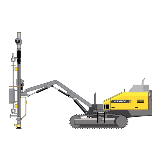
FlexiROC T35 R/T40 R 2 General 2.3 Principal components Principal components Rod handling equipment (RHS) Feeder Boom system Operator platforms Radiator Hydraulic oil cooler Hydraulic oil pumps Dust collector (DCT) Diesel engine Compressor No: 3171473547.1 en... -
Page 11: General System Description
FlexiROC T35 R/T40 R 2 General Hydraulic oil pumps Electric cabinet Radio receiver Track frames 2.4 General system description 2.4.1 General description of the drill rig This drill rig is a fully diesel-hydraulic drill rig designed for surface drilling applications such as in quarries and on construction sites. -
Page 12: Power Pack
FlexiROC T35 R/T40 R 2 General Emergency stop cable Emergency stop Receiver Compressor Hydraulic systems Air system Boom Dust collector DCT 2.4.2 Power pack The hydraulic drill rig is powered by a turbocharged, water-cooled diesel engine which is equipped with an afterburner chamber to reduce emissions. -
Page 13: Hydraulic System
FlexiROC T35 R/T40 R 2 General The emergency stop buttons/cables are connected in series with the diesel engine cut-out system. As soon as an emergency stop button/cable is activated, the diesel engine will be stopped immediately. Reset the emergency stop buttons before restarting the engine. The engine cannot be started while one of the emergency stops is still activated. - Page 14 FlexiROC T35 R/T40 R 2 General Rapid feed Rod handling Tramming motor, left Tramming motor, right Flow divider Percussion Drill feed Rotation RPC-F No: 3171473547.1 en...
-
Page 15: Hydraulic Pumps
FlexiROC T35 R/T40 R 2 General Positioning Winch Cooler motor Pressure adjustment Rotation adjustment Dust collector (DCT) Filler pump Filter Pump 4 Diesel engine Pump 1 Pump 2 Pump 3 Reversing valve 2.4.8 Hydraulic pumps Hydraulic pump 1 Pump 1 is the main pump in the hydraulic system and is of the axial piston type. The pump... -
Page 16: Air System
FlexiROC T35 R/T40 R 2 General Pump no. Flow (litre/min) Pressure (bar, max.) Table 2: Hydraulic pump output (2200 rpm) 2.4.9 Air system The air system consists of the compressor with oil separator, hoses and valves. The com- pressor is driven directly by the diesel engine. -
Page 17: Technical Data
Max. engine speed (2200 rpm) Drilling (2000 rpm) 3.1.3 Tilt angles FlexiROC T35 R / ROC T40 R NOTE: Stability is specified with respect to CE standards stipulating that rigs must not be operated on inclinations steeper than 20 degrees without the use of a winch. -
Page 18: Hydraulic Systems
Voltage 2 x 12 V/185 Ah Work lights Voltage 24 V/70 W Alternator Voltage 28V/95 Ah 3.1.6 Air system FlexiROC T35 R Description Data Compressor: C111 Max. air pressure 10.5 bar Free air delivery at 10.5 bar 127 l/s Working pressure 10.5 bar... -
Page 19: Others
FlexiROC T35 R/T40 R 3 Technical data Description Data Hydraulic systems total 320 l Fuel tank 330 l DEF tank 27 l Traction gear Compressor oil 24 l Lubricating oil tank 10 l Diesel engine oil 16 l Engine cooling system 35 l 3.1.9 Others... - Page 20 FlexiROC T35 R/T40 R 3 Technical data Transport position, alternative 1 Other dimensions No: 3171473547.1 en...
- Page 21 FlexiROC T35 R/T40 R 3 Technical data Coverage area Feeder angles of inclination Feed inclination angles with swing cylinder connected in various ways. No: 3171473547.1 en...
- Page 22 FlexiROC T35 R/T40 R 3 Technical data Normal position in downward-directed drilling Toe-hole drilling No: 3171473547.1 en...
-
Page 23: Daily Checks
FlexiROC T35 R/T40 R 4 Daily checks 4 Daily checks 4.1 Foreword This chapter provides instructions for daily inspection and maintenance to be carried out by the operator before each shift. Regarding weekly inspections ad other maintenance tasks, see separate instructions "Maintenance schedules". -
Page 24: Checklist
FlexiROC T35 R/T40 R 4 Daily checks 4.2.2 Checklist Check points. Feed holder with attach- Boom ment Boom head Boom support Feed cylinder with at- Winch wire rope with tachment hook Hose drum with cradle Winch with brackets Cylinder brackets... -
Page 25: Before Starting
FlexiROC T35 R/T40 R 4 Daily checks Remote control box Rubber bellows on The joint between the levers and switches upper and lower halves of the box must be well tightened. Seals on switches and The box must not be... -
Page 26: Status Field Symbols
FlexiROC T35 R/T40 R 4 Daily checks WARNING Serious injury Dangerous compressed air Can cause serious injury Release the pressure in the tank before removing the filler plug 4.3.2 Status field symbols The status field on the engine display shows information to the operator in the form of col- oured symbols. - Page 27 FlexiROC T35 R/T40 R 4 Daily checks Symbol Description Symbol Description Battery Compressor air filter Indicates that the Indicates that the com- voltage from the battery pressor air filter is is less than 24V clogged ECL collection Indicates that the ECL...
-
Page 28: Checks
FlexiROC T35 R/T40 R 4 Daily checks Symbol Description Symbol Description Coolant level Compressor temperat- Indicates that the coolant level to the en- Indicates that the com- gine is too low. Engine pressor temperature is stopped automatically too high. Engine... -
Page 29: Fuel Filter
FlexiROC T35 R/T40 R 4 Daily checks 4.3.4 Fuel filter Fuel filter. Check point Inspection Instructions Water separator Primary fuel filter Drain off the water (A). Table 9: Fuel filter. 4.4 Functionality test after start 4.4.1 Checks Check point Inspection Instructions... -
Page 30: Function Test While Drilling
FlexiROC T35 R/T40 R 4 Daily checks Check point Inspection Instructions NOTE: The return oil pressure gauge will show reliable readings once the oil has reached a temperature of at least 40º C (104ºF) Hydraulic pressure Visual check Observe the pressure gauges to... -
Page 31: Diesel Control Panel
FlexiROC T35 R/T40 R 4 Daily checks Check point Inspection Instructions the needle is in the red zone, the filter must be changed. Call for a service technician. Check all the pressure gauges to see that the hydraulic pres- sure is normal. Call for a service technician if there are any devi- ations. - Page 32 FlexiROC T35 R/T40 R 4 Daily checks No: 3171473547.1 en...
-
Page 33: Controls
FlexiROC T35 R/T40 R 5 Controls 5 Controls 5.1 Controls 5.1.1 General The equipment for filling up with fuel, hydraulic oil and compressor oil is located close to the appropriate tanks. General drawing Gradient meter Fire extinguisher No: 3171473547.1 en... -
Page 34: Remote Control Box
FlexiROC T35 R/T40 R 5 Controls Control panel for pressure and pressure gauges Test connections for the hydraulic circuits Display for diesel engine Electric cabinet 5.1.2 Remote control box WARNING Serious injury Danger of accidental operation May cause serious personal injury and damage to property... - Page 35 FlexiROC T35 R/T40 R 5 Controls Functions Remote control box. S100 Circuit breaker Flushing air Default: Full flushing air/ Dust collector active Default: Reduced flushing air/ Dust collector active Flushing air deactivated S101 Release button Rotation and feed cease Percussion ceases/ Normal mode NOTE: If the release button has not been reset, it will not be possible to restart rotation, percussion or feed.
- Page 36 FlexiROC T35 R/T40 R 5 Controls Open Drilling stops automatically S130 Mode selector knob for remote control box Adjustment mode while drilling Drilling/Shut-down/Preheating Positioning/Tramming/Winching S132 Drill rig stop active NOTE: Works only when radio system is active! S137 Switch for Tramming speed...
- Page 37 FlexiROC T35 R/T40 R 5 Controls S177 Switch, right Track oscillation Lower front section Neutral Raise the front S181 Circuit breaker Dust collector (DCT) Dust collector activated Dust collector inactivated S182 Sleeve grippers button Sleeve grippers to drill centre Sleep grippers to carousel...
-
Page 38: Right-Hand Multifunction Lever In Drilling Position
FlexiROC T35 R/T40 R 5 Controls Max. water mist S465 Button for zeroing hole depth R106 Winch traction potentiometer (when tramming) Clockwise - Increased pressure, more traction Anticlockwise - Reduced pressure, less traction Indicator lamp Flashes green quickly: Indicates that the remote control box is searching for... - Page 39 FlexiROC T35 R/T40 R 5 Controls Sector Function Drill feed reverse (when percussion active)/ Rapid feed reverse (when percussion inactive). If low percussion is activated manually, rapid feed re- verse can be obtained Drill rotation-Self-holding/air Rotation right Drill feed forwards (self-holding feed percussion...
-
Page 40: Left-Hand Multifunction Lever In Drilling Position
FlexiROC T35 R/T40 R 5 Controls Deactivates flushing air (deactivates rotation after 0.5 sec) Table 20: Rotation of multi-function lever when rotation and flushing air functions are active. 5.1.4 Left-hand multifunction lever in drilling position Sector description - Multi-function lever S260... -
Page 41: Right-Hand Multifunction Lever In Positioning Mode
FlexiROC T35 R/T40 R 5 Controls Neutral Closed rod grippers Table 22: Turning of multi-function lever S261 5.1.5 Right-hand multifunction lever in positioning mode Sector description - multi-function lever S261 Sector Function Boom lowering Neutral Boom lift Boom swing (left) Boom swing (right) Table 23: Sector description. -
Page 42: Left-Hand Multifunction Lever In Positioning Mode
FlexiROC T35 R/T40 R 5 Controls 5.1.6 Left-hand multifunction lever in positioning mode Sector description - Multi-function lever S260 Sector Function Feed tilt (spike forward) Neutral Feed tilt (spike rearward) Feed swing (left) Feed swing (right) Table 25: Sector description Feed extension down Feed extension up Table 26: Turning of multi-function lever S260... - Page 43 FlexiROC T35 R/T40 R 5 Controls Pressure adjustment and pressure gauges. Adjustment of RPCF Adjusting high percussion pressure Adjusting low percussion pressure Adjusting threading pressure Adjusting unthreading pressure Adjusting high drill feed pressure Adjusting low drill feed pressure Adjusting rotation speed...
-
Page 44: Pressure Adjustments And Pressure Gauges (Cop 1238 Series)
FlexiROC T35 R/T40 R 5 Controls Extra air outlet 5.1.8 Pressure adjustments and pressure gauges (COP 1238 series) NOTE: The pressure gauges must be checked during drilling. Pressure adjustment and pressure gauges. Adjustment of RPCF Adjusting high percussion pressure Adjusting low percussion pressure... -
Page 45: Control Panel For Diesel Engine And Directional Instrument
FlexiROC T35 R/T40 R 5 Controls Percussion pressure gauge Return oil pressure gauge Drill feed pressure gauge Lubrication oil pressure gauge Flushing air pressure gauge Rotation pressure gauge Extra air outlet 5.1.9 Control panel for diesel engine and directional instrument... - Page 46 FlexiROC T35 R/T40 R 5 Controls S180 Circuit breaker for compressor loading Compressor loaded Compressor unloaded S186A Signal Horn R189 Potentiometer for engine speed (active only when "high speed" is activated) S197 Work lights Work lights front and rear on...
-
Page 47: Display For Engine And Directional Instruments
FlexiROC T35 R/T40 R 5 Controls 5.1.10 Display for engine and directional instruments Display for engine and directional instruments Display for engine and directional instruments. The diesel engine is controlled by an electronic unit that continually sends information to the engine display. The engine display consists of two fields and nine function buttons (See illustration: Engine display). - Page 48 FlexiROC T35 R/T40 R 5 Controls Primary field The push buttons a - c provide direct access to the selected graphic presentation. To se- lect a graphic presentation: select the desired presentation using the arrow keys and con- firm by pressing the Enter key.
- Page 49 FlexiROC T35 R/T40 R 5 Controls Symbol Description Symbol Description Engine service Rock drill service Indicates time for en- Indicates time for rock gine service according drill service according to to preselected number preselected number of of hours hours Communication fault...
- Page 50 FlexiROC T35 R/T40 R 5 Controls Symbol Description Symbol Description Illuminates when regen- Is shown when the soot eration has started. content is > 80%. Automatic regenera- Self-holding of drilling tion blocked lever ceases Used when there is a Illuminates when the...
- Page 51 FlexiROC T35 R/T40 R 5 Controls Menus Main menu and shortcut menus Main menu Engine information Directional instrument Drilled length GPS compass (additional equipment) Statistics System Settings No: 3171473547.1 en...
- Page 52 FlexiROC T35 R/T40 R 5 Controls 1 Main menu Main menu. Opens graphical presentation for diesel engine Opens graphical presentation for directional in- strument Opens graphical presentation for hole length/ver- tical depth Opens graphical presentation for statistics Opens graphic presentation for system status...
- Page 53 FlexiROC T35 R/T40 R 5 Controls Bar graph showing engine temperature. The bar changes colour when changing to warning, first yellow warning then red warning. Bar graph showing hydraulic oil temperature. The bar changes colour when changing to warning. First yellow warning then red warning.
- Page 54 FlexiROC T35 R/T40 R 5 Controls Directional instrument - digital display mode. Shows required inclination angle of the feeder in relation to the blast direction Shows desired lateral angle of the feeder Counter showing actual angle of inclination in rela-...
- Page 55 FlexiROC T35 R/T40 R 5 Controls Activation of laser receiver (optional equipment). At activation the laser symbol with grey back- ground is shown in the status field and after a hit the background changes to green. Hole Depth The symbol indicates that vertical hole depth is...
- Page 56 FlexiROC T35 R/T40 R 5 Controls 4 GPS compass GPS compass. Current value Locking the current value for blasting direction Last locked value Activating the GPS compass 5 Statistics Statistics menu. Fuel information Engine information Time/consumption No: 3171473547.1 en...
- Page 57 FlexiROC T35 R/T40 R 5 Controls 5.1 Fuel information Fuel information Fuel consumption (litres per hour) Fuel pressure Total fuel consumption Fuel level DEF (Diesel Exhaust Fluid) level 5.2 Engine information Engine information. Power output Engine oil pressure Charge air pressure...
- Page 58 FlexiROC T35 R/T40 R 5 Controls 5.3 Time - length - specific charging Time - length - specific charging menu. Reset and display of fuel consumption Reset and display of engine hours Reset and display of percussion hours Reset and display of total hole length/hole depth -...
- Page 59 FlexiROC T35 R/T40 R 5 Controls 6 System System menu. Opens graphic presentation for CAN BUS commu- nication Opens graphical presentation for sensor informa- tion Opens graphical presentation of ECM 6.1 Communication Communication menu. D173 GPS D510 I/O modules D170 Boom axis sensor...
- Page 60 FlexiROC T35 R/T40 R 5 Controls 6.1.1 Module status Symbols in the previous menu marked with a blue frame can be activated using Enter. Fol- lowing which the current status of the modules is shown. Current status of D510 I/O module 6.2 Sensor information PMAI/PMAI1/PAMI2/PMO...
- Page 61 FlexiROC T35 R/T40 R 5 Controls Sensor Function Status Event ~8200 mV Aim device straight ahead Aim device max left PLC/Y105 Reset hole length 0-10000 mV When zeroing B172 Length meter pulses When measuring Table 31: Sensor information Sensor Function Status...
- Page 62 FlexiROC T35 R/T40 R 5 Controls Sensor Function Status Event K200 Stop Engine Engine stopped PLC/X4 Drill stop/hole length Desired hole length ob- reached tained Table 34: Sensor information NOTE: Any status other than the one given indicates a sensor fault or that something else happened to the function.
- Page 63 FlexiROC T35 R/T40 R 5 Controls Pos. Function Selection of drilled length measurement method: Mark the box using the arrow keys and confirm with Enter. Select hole depth gauge or vertical depth gauge using the arrow keys and confirm with Enter.
- Page 64 FlexiROC T35 R/T40 R 5 Controls Pos. Function When the preset number of drill-metres has been reached the "Drill bit grinding" symbol will be shown in the display status field. The interval is set in accordance with the steps below.
- Page 65 FlexiROC T35 R/T40 R 5 Controls 7.2 Display lighting and background colour Lighting and background colour menu. Pos. Function Light adjustment: When the plus button is selec- ted, the background lighting increases when Enter is pressed. When the minus button is selected, the background lighting decreases when Enter is pressed.
- Page 66 FlexiROC T35 R/T40 R 5 Controls Service menus Setting the service interval and reporting service. 7.3.1 Sensor calibration Sensor calibration menu. Feed dump angle Feed swing Boom Swing Cradle position Information on cradle speed GPS compass Select a setting using the arrow keys and then reset using Enter. See the chapter on "Op- erating the directional instrument"...
- Page 67 FlexiROC T35 R/T40 R 5 Controls Run the rock drill cradle all the way up Go to menu 7.3.1 "Sensor calibration" and reset "Cradle position"(e). Go to the "Sensor information" menu and lower the cradle slowly until sensor B104 gives an indication (0 becomes 1) Go back to the "Sensors/calibration"...
- Page 68 FlexiROC T35 R/T40 R 5 Controls The distance between the laser sensor and the drill bit should be in the box (a). This value needs to be adjusted in the following cases: Changing length of drill steel Replacement of laser sensor Load/Save parameters Calibration values for the direction instrument can be saved on a USB card in this menu.
-
Page 69: Other Controls
FlexiROC T35 R/T40 R 5 Controls 5.2 Other controls 5.2.1 Electric cabinet A1 electric cabinet. Battery charger for remote control box batteries. Settings for ECG and ECL Timer diesel heater (optional) Grease brushes (Option) The amount of grease being pumped can be ad- justed with the time relay K449. -
Page 70: Test Connections For The Hydraulic Circuits
FlexiROC T35 R/T40 R 5 Controls The shape of the pulse is adjusted on the bottom knob. It must always be at B. NOTE: The entire system can be turned off by stopping the supply of air with the cock by the grease pump. -
Page 71: Front Cover
FlexiROC T35 R/T40 R 5 Controls 5.2.3 Front cover Front cover When the front cover is fully opened it is locked in open position. To close the front cover, press button (a) on the gas spring. No: 3171473547.1 en... - Page 72 FlexiROC T35 R/T40 R 5 Controls No: 3171473547.1 en...
-
Page 73: Operating
FlexiROC T35 R/T40 R 6 Operating 6 Operating 6.1 Activating the remote control box WARNING Serious injury Danger of accidental operation May cause serious personal injury and damage to property The operator must always have an overview of the drill rig and the remote control box... - Page 74 FlexiROC T35 R/T40 R 6 Operating Check that no emergency stop is activated. Reset the emergency stops with the reset button (C). No: 3171473547.1 en...
- Page 75 FlexiROC T35 R/T40 R 6 Operating Emergency stop location Reset the emergency stop on the radio box (A). Turn the starter key on the diesel panel to the On position, S139 to position (b). No: 3171473547.1 en...
- Page 76 FlexiROC T35 R/T40 R 6 Operating Press the reset button (A) on the diesel panel. Activate the radio box with one rapid press of the start button S186 (B). Then press the same button for 2-3 seconds. No: 3171473547.1 en...
-
Page 77: Diesel Engine Starting
FlexiROC T35 R/T40 R 6 Operating è A symbol will light up on the diesel engine display once the remote control box has been activated. Unless a control is used on the remote control box within 10 seconds, the box will go into so-called "standby mode". - Page 78 FlexiROC T35 R/T40 R 6 Operating Turn the ignition key to ignition (b). Ignition key S139. Reset the emergency stop with the reset button (A) on the diesel panel. Activate the radio box with one rapid press of the start button S186 (B). Then press the same button for 2-3 seconds.
-
Page 79: Regeneration (Tier 4 Final)
FlexiROC T35 R/T40 R 6 Operating è A symbol will light up on the diesel engine display once the remote control box has been activated. Press the start button S186 (B) and then (within 5 seconds) press the button (C) for Suction cup position down (c) and hold for more than one second, then press Suction cup (C) position up (a) until the engine starts. -
Page 80: General
FlexiROC T35 R/T40 R 6 Operating 6.3.1 General Regeneration is a process that burns out the soot from the diesel engine's particulate filter. In normal conditions, regeneration starts automatically and without affecting the rig's per- formance. The operator cannot influence the regeneration process. Regeneration is started and stopped without a message being shown on the display. -
Page 81: Stopping The Diesel Engine
FlexiROC T35 R/T40 R 6 Operating Switching off the engine Repeatedly bypassing delayed shutdown (DES) of the engine damages the DEF injector. Each time delayed shutdown is bypassed it is recorded in the event log in the rig's control system. - Page 82 FlexiROC T35 R/T40 R 6 Operating NOTE: Repeatedly bypassing delayed shutdown (DES) of the engine damages the DEF injector. Each time delayed shut- down is bypassed it is recorded in the event log in the rig's control system. Press the start button (B) and then (within 5 seconds) press the button for Suc- tion Hood Down (C) position (c) and hold until the engine stops.
-
Page 83: Tramming
FlexiROC T35 R/T40 R 6 Operating 6.6 Tramming 6.6.1 Tramming WARNING Serious injury Risk of dumping/sliding May cause severe personal injury and damage to property Always check the prevailing ground conditions where the rig shall be operated Keep the track oscillation pedals open during tramming... - Page 84 FlexiROC T35 R/T40 R 6 Operating WARNING Serious injury Danger of accidental operation May cause serious personal injury and damage to property The operator must always have an overview of the drill rig and the remote control box Always check that the controls are correctly adjusted before operating...
- Page 85 FlexiROC T35 R/T40 R 6 Operating NOTE: The gradient meter shows the chassis frame inclination and not the actual ground inclination. Tramming Put the remote control box into tramming and positioning mode. Knob S130, position (h). Position the feeder against the feed support (A). Multi-function levers S261 and S280.
-
Page 86: Checking After Tramming
FlexiROC T35 R/T40 R 6 Operating NOTE: Low tramming speed gives the highest traction and vice versa. Operate the levers to move the drill rig in the desired direction. Levers S174 and S175. NOTE: If one crawler track is operated while the other is stationary the tracks are subjected to unnecessary stresses. -
Page 87: Tramming, Uphill
FlexiROC T35 R/T40 R 6 Operating 6.8.2 Tramming, uphill Extend the boom system and use it as a counterweight when tramming uphill. Left: Correct position for tramming uphill. Right: Wrong position. 6.8.3 Tramming, downhill Retract the boom system maximally towards the drill rig. -
Page 88: Using The Winch When Tramming
FlexiROC T35 R/T40 R 6 Operating Left: Correct position for traversing inclines. Right: Wrong position. 6.9 Using the winch when tramming WARNING Serious injury Risk from dumping and moving parts May cause serious personal injury and damage to property Ensure that unauthorised personnel are outside of the working area... -
Page 89: General
FlexiROC T35 R/T40 R 6 Operating WARNING Serious injury Danger of accidental operation May cause serious personal injury and damage to property The operator must always have an overview of the drill rig and the remote control box Always check that the controls are correctly adjusted before operating... - Page 90 FlexiROC T35 R/T40 R 6 Operating WARNING Serious injury Risk of dumping May cause severe personal injury and damage to property Keep the winch cable continuously taught Activate the remote control box (see chapter: Activating the remote control box). Make sure the remote-control box is in tramming mode. Knob S130, position (h).
- Page 91 FlexiROC T35 R/T40 R 6 Operating Remote control box. Set the winch potentiometer to desired pressure by turning it. Potentiometer R106. Control panel for diesel engine. Activate the winch circuit. Switch S172, position (a). Activate wind-in manually to ensure the lock mechanism is fully engaged in the drum before putting strain on the winch.
-
Page 92: Tramming Down Inclines
FlexiROC T35 R/T40 R 6 Operating Left: The winch lock mechanism is completely disengaged. Right: The winch lock mechanism is fully engaged. Reverse up the incline using the tramming levers. Make sure that the wire is kept taut constantly. 6.9.3 Tramming down inclines Check that the track oscillation lock is deactivated. -
Page 93: Before Drilling
FlexiROC T35 R/T40 R 7 Before drilling 7 Before drilling 7.1 Safety WARNING Serious injury May cause severe personal injury Ensure that unauthorised personnel are not within the working area Do not approach the area surrounding rod/pipe gripper or carousel... - Page 94 FlexiROC T35 R/T40 R 7 Before drilling Remote control box. Position the feed beam horizontally. Right and left multifunction levers. Put the remote-control box in drilling mode. Knob S130, position (b). Move the rod handling arms into the carousel. Left-hand multifunction lever, position (a).
-
Page 95: Setting Up For Drilling
FlexiROC T35 R/T40 R 7 Before drilling Run the rock drill up with the drill rod until it stops at the automatic stop in the drill steel. Right-hand multifunction lever, position (c). When switch S113 is activated, the cradle will be stopped automatically in the right position for inserting the drill rod into the carousel. - Page 96 FlexiROC T35 R/T40 R 7 Before drilling CAUTION Risk of injury Risk of feed beam bending To avoid overloading the feeder, do no use the cylinder alone for lowering the boom, or the cylinder for feed extension individually to place the feeder against the ground Do not raise the front section of the track frame from the ground Put the remote control box in tramming and positioning mode.
-
Page 97: Setup For Drilling - General Principles
FlexiROC T35 R/T40 R 7 Before drilling Incorrect set up. Position the feed beam to desired inclination and place the spike firmly against the ground without lifting the drill rig. Right and left-hand multifunction lever. NOTE: Do not lift the drill rig with the feeder! 7.4 Setup for drilling - General principles... -
Page 98: Downhill Setup
FlexiROC T35 R/T40 R 7 Before drilling 7.4.2 Downhill setup Left: Correct position for drilling uphill. Right: Wrong position. 7.4.3 Downhill setup Set up the drill rig as close to the horizontal as possible. Left: Correct position for drilling downhill. Right: Wrong position for drilling downhill. -
Page 99: Drilling
FlexiROC T35 R/T40 R 8 Drilling 8 Drilling 8.1 Start of drilling WARNING Serious injury Danger of accidental operation May cause serious personal injury and damage to property The operator must always control of the rig and the remote control box... - Page 100 FlexiROC T35 R/T40 R 8 Drilling Diesel panel Check that the switch for flushing air is in position for REDUCED/FULL FLUSHING AIR. Flushing air starts at the same time as percussion is started. Switch S100, posi- tion (a). Close the drill-steel supports. Switches S119 and S187, position (a).
-
Page 101: Manual Drill Feed
FlexiROC T35 R/T40 R 8 Drilling NOTE: Use the drill lever intermittently through sector (b) until solid rock is reached. NOTE: Collaring with feed too high will make the drill bit veer off in the wrong direction and result in a deviating hole and bent drill string. -
Page 102: Boom/Feed Adjustment While Drilling
FlexiROC T35 R/T40 R 8 Drilling The holding circuit has now ceased and the feed can be controlled manually in sec- tors (f) and (a). To continue with self-holding, move the multi-function lever back to sector (j). 8.1.2 Boom/feed adjustment while drilling... -
Page 103: Break Loose
FlexiROC T35 R/T40 R 8 Drilling If water emerges from the drill hole Switch off DCT to protect the filters Table 37: The borehole: 8.3 Break loose WARNING Serious injury Danger of accidental operation May cause serious personal injury and damage to property... -
Page 104: Automatic Break Loose
FlexiROC T35 R/T40 R 8 Drilling Leave percussion active until all the drill rod couplings/couplings are loose. Then deactivate percussion by pressing button S101 once. NOTE: Remember that the rotation stop button S101 is a "toggle switch", rotation will not start unless the button is reset! For informa- tion see chapter: Controls NOTE: High percussion is better when releasing. - Page 105 FlexiROC T35 R/T40 R 8 Drilling Remote control box. Make sure that the upper drill-steel support (for locking the sleeve) is closed. (See section on controls, upper drill-steel support switch.) Make sure that the rapid feed stop's rod handling positions are deactivated in order to allow the rock drill to stop above the rod carousel.
-
Page 106: Unthreading And Extracting
FlexiROC T35 R/T40 R 8 Drilling If there is not a drill steel in the rod grippers, the carousel must first be rotated so that there is a rod in position. Left multi-function lever, sector (d) or (e). Sector description - Left multi-function lever. - Page 107 FlexiROC T35 R/T40 R 8 Drilling NOTE: The rod grippers are opened automatically when the carousel rotates. Applies only to FR T30 R -01 with RHS. Make sure the shank joints are broken loose. Activate the rapid feed stops. Switch S113, position (a).
-
Page 108: Changing Drill Bit
FlexiROC T35 R/T40 R 8 Drilling Sector description, right multi-function lever. Return the left-hand multi-function lever to neutral position (loose grip). Activate unthreading by moving the right multi-function lever to sector (i) (break loose rod joints). Pull back on the right-hand multi-function lever (rock drill stops at limit switch). -
Page 109: Action In Case Of Drilling Problems
FlexiROC T35 R/T40 R 8 Drilling Make sure that the rotation lever is in neutral. Move the drill bit forward until it is pressed against the rock. Switch on high percussion pressure for several seconds. Switch off percussion pressure when the drill bit has loosened. If the percussion pres- sure is engaged for too long then the drill steel can detach from the shank adapter. -
Page 110: Difficulties In Loosening The Coupling Sleeve
FlexiROC T35 R/T40 R 8 Drilling 8.7.3 Difficulties in loosening the coupling sleeve The best method of loosening the coupling sleeve is to "drill" the last few centimetres without feed pressure and rotation, leaving percussion active for a few seconds to break loose the coupling sleeve. -
Page 111: Angle Instruments
FlexiROC T35 R/T40 R 9 Angle instruments 9 Angle instruments 9.1 General Depending on the equipment level chosen, the drill rig can be equipped with one of the fol- lowing alternatives: Angle instrument with aim device (standard equipment). Laser plane instrument (option). - Page 112 FlexiROC T35 R/T40 R 9 Angle instruments Directional instrument - graphic display mode Spike forward = +º Spike back = -º Table 38: Feed movement - Tilt (feeder forward and reverse) Spike left = +º Spike right = -º Table 39: Feed movement - Swing (feeder right and left) NOTE: The display shows Tilt movement forwards = +º...
-
Page 113: Laser Plane Instrument (Option)
FlexiROC T35 R/T40 R 9 Angle instruments Reset: Resetting the drilled length instrument. Before the start of each hole, the drill bit should be positioned against the ground. Use the arrow keys to mark the button by the symbol and press Enter. -
Page 114: Gps Compass (Option)
FlexiROC T35 R/T40 R 9 Angle instruments Drilled length Activation of the laser plane function: Mark the field by moving with the arrow keys until the button is blue and then press Enter to confirm. Laser plane function indication: The indicator is lit in the status field of the display when the function is active. -
Page 115: Drilled Length Instrument
FlexiROC T35 R/T40 R 9 Angle instruments Shows the aim device's compass direction Shows the compass direction selected for locking Shows whether the function is off or on Table 41: Menu F4 Turn the aim device to the required compass direction. - Page 116 FlexiROC T35 R/T40 R 9 Angle instruments Main menu The depth instrument has the following functions: Drilled length Indication of selected measurement method The method of measurement is selected in the "Settings" menu. Use the arrow keys to mark the button by the symbol. Press Enter to toggle between the two alternatives. Use the ESC key to leave the menu when the desired symbol is shown.
-
Page 117: Settings
FlexiROC T35 R/T40 R 9 Angle instruments Number of drill rods. Reset of drilled length counter: Before the start of each hole, the drill bit should be posi- tioned against the ground. Use the arrow keys to mark the button next to the symbol and press Enter. - Page 118 FlexiROC T35 R/T40 R 9 Angle instruments The current setting is shown in the field at the bottom left. If this differs from the equip- ment to be used, it must be changed. Use the arrow keys to mark the correct type of equipment and confirm with Enter.
-
Page 119: Calibration
FlexiROC T35 R/T40 R 9 Angle instruments D171 Inclination sensor B172 Length Sensor Switch Adjusting screws Carefully open the cover and set the DIP switches as illustrated below. The illustration is also found on the inside of the A1 cabinet door. - Page 120 FlexiROC T35 R/T40 R 9 Angle instruments Sensor calibration menu. Feeder tipping angle Feed swing Boom Swing Cradle position Information on cradle speed If any value is not 0, it must be reset for the instrument to function correctly. Use the arrow keys to mark one button at a time and press Enter to reset the value.
-
Page 121: Operation
FlexiROC T35 R/T40 R 9 Angle instruments Calibration sensor. The symbol for "Calibrate length sensor" in the status bar of the display will be extin- guished once the length sensor is calibrated. Warning symbol "Length sensor not calibrated". 9.1.7 Operation Move the rig to the drill site and set it up in the desired position. - Page 122 FlexiROC T35 R/T40 R 9 Angle instruments Set the desired hole length / vertical depth in the drilled length instrument's menu if automatic drill stop is to be used. Position the drill bit against the ground and reset the drilled length instrument either directly in the angle instrument's menu or by first selecting the drilled length instru- ment's menu and then resetting it.
-
Page 123: Options
FlexiROC T35 R/T40 R 10 Options 10 Options 10.1 Thread lubrication 10.1.1 Thread lubrication with brushes Function Drill steel threads are lubricated using two brushes (C) mounted on the RHS carousel lower bracket. Grease comes from a pump (B) placed in a grease container (A) at the front of the chassis frame. - Page 124 FlexiROC T35 R/T40 R 10 Options Brushes for thread lubrication. Operation Lubrication is regulated with a switch that is described in the chapter, Controls. During normal use, the system will operate automatically. The grease pump will then operate when the rod handling lever is in position to move a rod to the drill centre. This means that each time a rod is moved out from the carousel, a certain amount of grease will be pumped to the brushes that the rod threads subsequently pass.
-
Page 125: Electric Filler Pump
FlexiROC T35 R/T40 R 10 Options 10.2 Electric filler pump 10.2.1 Electric pump for filling fuel Electric filler pump The pump is used to fill fuel. Make sure that the hose and the filter are clean. Connect the attached hose to the fuel source. -
Page 126: Water Mist System
FlexiROC T35 R/T40 R 10 Options The electric filler pump will stop automatically when the drill rig fuel tank is full. It will also stop if the source of fuel runs out. 10.3 Water mist system 10.3.1 General The water mist system is a pressurised system that is pressurised from the drill rig's air system. - Page 127 FlexiROC T35 R/T40 R 10 Options Drain outlet. Drain cock. The system is filled with pure water via (A) the pressure tank cap. The system pressure can be read on (C) the tank pressure gauge. The system is drained from water through the cock (E).
- Page 128 FlexiROC T35 R/T40 R 10 Options Water mist system. Fine adjustment of water mist Valve. Valve. Strainer Cock for adjusting the water mist system. No: 3171473547.1 en...
-
Page 129: Water Mist System 225 Litres
FlexiROC T35 R/T40 R 10 Options When the circuit breaker for the water mist system is in position (a) (valves fully open), the quantity of water is controlled solely by the cock (J) on the water mist system. The cock should normally be set so that water mist emerges from the drill bit. - Page 130 FlexiROC T35 R/T40 R 10 Options Operation Pressure tank and drill panel The water tank must be filled with pure water and possibly dust binding additive through the filler valve on top of the tank (A). The tank can be drained through the valve on the bottom of the tank (B).
- Page 131 FlexiROC T35 R/T40 R 10 Options Setting WARNING Serious injury Never carry out maintenance work while the drill rig is in operation Make sure that the hydraulic, water and air systems are depressurised and that the electrical system is without current before starting any work The system has two possible settings: Basic setting with shut-off valve (5).
- Page 132 www.atlascopco.com...
Need help?
Do you have a question about the FlexiROC T35 R and is the answer not in the manual?
Questions and answers