
Related Manuals for Atlas Copco PowerROC T50 Tier 4


Summary of Contents for Atlas Copco PowerROC T50 Tier 4
- Page 1 Atlas Copco PowerROC T50 Tier 4 Operator's instructions PM NO. 9852 3289 01a 2014-09...
- Page 2 Atlas Copco (Nanjing) Construction & Mining Equipment Ltd., China All product names in this publication are trademarks of Atlas Copco. Any unauthorized use or copying of the contents or any part thereof is prohibited. Illustrations and photos may show equipment with optional extras.
-
Page 3: Table Of Contents
3.1 PowerROC T50 Tier 4 ........ - Page 4 5.3 Pressure gauges ............30 5.4 Engine display .
- Page 5 8.6.4 Hole deflection ........... 85 Options .
-
Page 7: Safety
1 Safety 1 Safety 1.1 Reference Note Always read the information in the Safety document before starting to use the rig or starting maintenance work. 1250 0099 89... - Page 8 1 Safety...
-
Page 9: General
See separate instructions for documentation on the rock drill, the diesel engine and certain other components. For other questions refer to the local Atlas Copco company office. Addresses and telephone numbers are in the Maintenance instructions. 2.2 Application The drilling equipment is designed mainly for drilling blast holes in e.g. -
Page 10: Principal Components
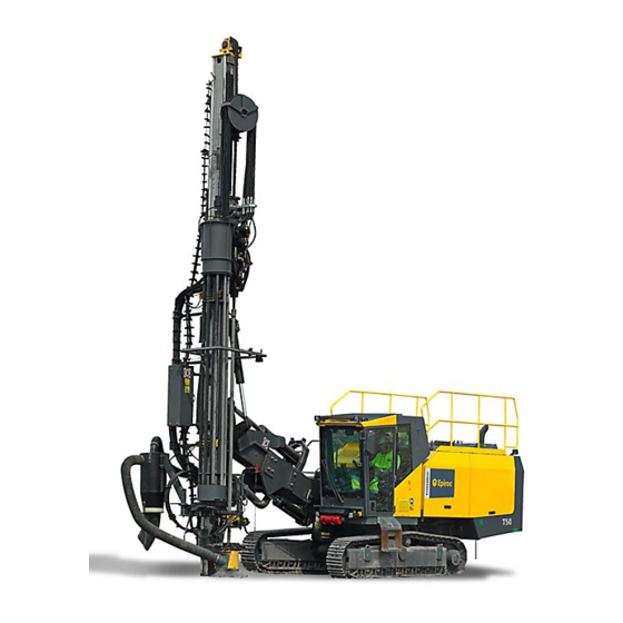
2 General 2.3 Principal components Figure 1 Principal components Compressor Diesel engine Operator's cab Control panel for drilling Boom Feeder Rod handling system (RHS) Upper drill-steel support Lower drill-steel support... -
Page 11: General System Description
2 General Track frames Feed motor Dust collector (DCT) Engine Radiator Compressor and hydraulic oil cooler 2.4 General system description 2.4.1 General description of the drill rig This drill rig is a fully diesel-hydraulic drill rig designed for surface drilling applica- tions such as in quarries and on construction sites. -
Page 12: Wagon Frame With Track Frames
2 General Feed Rock Drill Tracks Cooling System Lube System Drill-steel Support (DS) 2.4.2 Wagon frame with track frames The diesel engine, chassis, dust collector, hydraulic system, air system and boom system are mounted on the wagon frame. The wagon frame comprises a frame with the operator's cab/platform mounted on the left. -
Page 13: Boom System
2 General 2.4.4 Boom system The boom system consists of boom body, telescopic boom, boom head, feed holder and associated hydraulic cylinders. The boom system is controlled by directional valves for positioning the feed with the rock drill at different distances and direc- tions. - Page 14 2 General Pump no. Description Dust collector, Oil pre-heater Cooler for compressor and hydraulic oil Cooler for diesel engine The hydraulic oil tank is located on the right-hand side of the drill rig. The coolers are located at the rear of the wagon. (For further details, See Figure 3 Hydraulic system functions)
-
Page 15: Air System
2 General Filter Return Oil Fill Pump Cooler (Engine) Cooler (Compressor And Hydraulic) Position Percussion Feed Load Sensor Water Mist Pilot Pressure Tramming Rotation Load Sensor Oil Pre-heater Track oscillation Support leg 2.4.8 Air system The air system consists of the compressor with oil separator, hoses and valves. The compressor is driven directly by the diesel engine. - Page 16 2 General...
-
Page 17: Technical Data
2 * 12 V/200 Ah Working lights Front 4 * 70 W Rear 2 * 70 W Feeder 2 * 70 W Air system PowerROC T50 Tier 4, Compressor C146 Max. air pressure 10.5 bar Free air delivery at 10.5 bar 232 L/s Capacities... - Page 18 3 Technical data Hydraulic systems Hydraulic oil tank 380 L Hydraulic system, total 470 L Fuel tank 500 L Traction gear Compressor oil 63 L Lubricating oil tank 5.25 L Diesel engine 30 L Engine cooling system 51 L Climate unit Refrigerant, type R134A Refrigerant, quantity...
-
Page 19: Dimensions
3 Technical data 3.2 Dimensions 10800 Figure 4 Transport dimensions Figure 5 Measured from above... - Page 20 3 Technical data 3640 5330 Figure 6 Measured from the side...
- Page 21 3 Technical data 3644 2810 4267 3324 4253 4375 Figure 7 Coverage area from the side...
- Page 22 3 Technical data Figure 8 Coverage area from above Figure 9 Boom swing angle from above...
- Page 23 3 Technical data Figure 10 Feeder angles of inclination Figure 11 Coverage area for bottom-hole drilling...
- Page 24 3 Technical data Figure 12 Front face horizontal drill coverage area...
-
Page 25: Daily Checks
4 Daily checks 4 Daily checks 4.1 Foreword This chapter provides instructions for daily inspection and maintenance to be carried out by the operator before each shift. Regarding weekly inspections and other maintenance tasks, see separate instructions “Maintenance schedules”. 4.2 Extra safety check 4.2.1 Safety DANGER •... -
Page 26: Checklist
4 Daily checks Before each shift starts an extra and thorough visual safety check should be carried out in order to detect: • Damage that could give rise to structural weakness or cracks. • Wear that could have the same consequences. •... -
Page 27: Before Starting
4 Daily checks Hose drum with cradle Cylinder bracket Boom/boom head Boom support with pivot Operator's cab with brackets Track frames with attachments Feed Motor 4.3 Before starting 4.3.1 Safety WARNING • Danger of moving parts. • Can cause serious injuries. •... -
Page 28: Drill-Steel Support
4 Daily checks 4.3.2 Drill-steel support Figure 14 Drill-steel support Table 1 Drill-steel support Check point Control object Action Grease nipples Fill grease into the grease nipples. Cylinder bracket, drill-steel Check the torque. See table “Atlas supports Copco Standard torques”. Lock nut for adjusting screw, Check the torque. -
Page 29: Drill Rig
4 Daily checks 4.3.3 Drill rig Table 2 Drill rig Check point Inspection Instructions Drill rig Visual check Check for any signs of leaks, damage, breakage or cracks. 4.3.4 Engine package Table 3 Engine package Check point Inspection Instructions Engine/Compressor Visual check Check for leakage around the engine and compressor. -
Page 30: Compressor Tank
4 Daily checks 4.3.5 Compressor tank Figure 15 Compressor tank Table 4 Compressor tank Check point Control object Action Tank, draining Open drain plug (A). Drain the water. The drill rig must have been standing still for one hour before the water can be drained. -
Page 31: Electrical System
4 Daily checks 4.3.6 Electrical system Figure 16 Electrical system Table 5 Electrical system Check point Control object Action Working lights Check the function of all the working lights. Emergency stop Attachment. Check each emergency stop individu- buttons/cable ally. The engine must stop. Before checking the next emergency stop the previous one must be reset before restarting. -
Page 32: Functionality Test After Starting
4 Daily checks 4.4 Functionality test after starting 4.4.1 Checks Note The emergency stop buttons and cable must be checked before each shift and after tramming. Table 6 Checks Check point Inspection Instruction Emergency stop but- Function Check each emergency stop individually. The tons (all) and the emer- engine must stop! gency stop cable on the... -
Page 33: Function Test While Drilling
4 Daily checks 4.5 Function test while drilling 4.5.1 Hydraulic hoses to rock drill Table 8 Hydraulic hoses Check point Inspection Instructions The rock drill Abnormal vibration Check the accumulator. For further details in the hydraulic see “Maintenance instructions” for the hydraulic hoses hoses. -
Page 34: Engine Display
4 Daily checks 4.5.3 Engine Display Figure 18 Engine Display Table 10 Engine Display Check point Inspection Instructions Engine Display Visual check Check that no fault indicator comes on. In the event of a fault indication, stop the rig and rectify the fault. 4.5.4 Dust collector (DCT) Table 11 Dust collector (DCT) Check point... -
Page 35: Controls
5 Controls 5 Controls 5.1 General The controls and gauges are located inside the operator's cab. The equipments for filling fuel, hydraulic oil and compressor oil are located near the respective tank. 5.2 Cab Figure 19 Cab Gauge panel Gradient meter Engine control panel Tramming control panel Control panel for optional equipment... -
Page 36: Pressure Gauges
5 Controls RHS control lever Tramming lever Rod handling control panel Drilling lever Carousel control panel Air conditioner Emergency stop Fire extinguisher Hammer for emergencies 5.3 Pressure gauges Note The pressure gauges must be checked during drilling. Figure 20 Pressure gauge panel... -
Page 37: Engine Display
5 Controls Fuel level gauge Hydraulic oil temperature gauge Air discharge temperature gauge Flushing air pressure gauge Feed pressure gauge Rotation pressure gauge Percussion pressure gauge Damper pressure gauge Engine display Engine oil pressure gauge Engine coolant temperature gauge Low hydraulic oil indicator Low fuel indicator Hydraulic oil filter restriction indicator Air intake filters restriction indicator... - Page 38 5 Controls Display Some of the engine and transmission parameters which may be displayed in standard or metric units on the screen. Menu key Enter or exit menu screens Left arrow key Scroll the screen or move the parameter selection to the left or upward. Right arrow key Scroll the screen and move the parameter selection to the right or downward.
-
Page 39: Engine Control Panel
5 Controls 5.5 Engine control panel S189 S130 S186 S800 S139 Figure 22 Engine control panel S800 Preheating switch (option) S139 Ignition switch a = OFF b = ON c = START S189 Engine speed switch a = LOW ENGINE SPEED b = HIGH ENGINE SPEED The engine speed can be switch between 1200 r/min and 1800 r/min directly by operating switch S189. -
Page 40: Tramming Control Panel
5 Controls 5.6 Tramming control panel S803 S130A S176 S445 S177 Figure 23 Tramming control panel S803 DCT/RHS control lever a = FULL AIR, DCT ON b = ROD HAND SYSTEM (RHS) c = REDUCED AIR, DCT ON d = FULL AIR e = NEUTRAL S445 Track oscillation floating switch... -
Page 41: Control Panel For Optional Equipment
5 Controls 5.7 Control panel for optional equipment Figure 24 Control panel for optional equipment Water mist system switch a = REDUCTED FLOW b = NEUTRAL c = MAXIMUM FLOW Water flow adjusting knob Turn clockwise = INCREASE Turn counterclockwise = DECREASE Low water level indicator Super rotation switch a = ON... -
Page 42: Hydraulic Pressure Control Panel
5 Controls 5.8 Hydraulic pressure control panel Figure 25 Hydraulic pressure control panel Feed pressure adjusting knob Turn clockwise = INCREASE Turn counterclockwise = DECREASE Percussion pressure adjusting knob Turn clockwise = INCREASE Turn counterclockwise = DECREASE Rotation speed adjusting knob Turn clockwise = INCREASE Turn counterclockwise = DECREASE... -
Page 43: Position Control Panel
5 Controls 5.9 Position control panel Figure 26 Position control panel Feeder control lever a = FEED SWING (Spike left) b = FEED SWING (Spike right) c = FEED TILT (Spike rearward) d = FEED TILT (Spike forward) e = NEUTRAL Boom control lever a = BOOM SWING RIGHT b = BOOM SWING LEFT... -
Page 44: Tramming Levers
5 Controls 5.10 Tramming levers Figure 27 Tramming levers 1 / 2 Left/Right Tramming lever a = FORWARD b = NEUTRAL c = BACKWARD Note If one crawler track is operated while the other is stationary, the tracks are sub- jected to unnecessary stresses. -
Page 45: Drilling Lever
5 Controls 5.11 Drilling lever Figure 28 Drilling lever The drilling lever is a multi-functional lever which controls functions including feed and tramming: S446A Percussion pressure switch a = HIGH PERCUSSION PRESSURE c = LOW PERCUSSION PRESSURE S446B Percussion switch a = ON c = OFF S449... -
Page 46: Control Panel For Ds/Suction Hood
5 Controls Drilling lever a = FEED DWON b = NEUTRAL c = FEED UP d = ROTATE COUNTERCLOCKWISE e = ROTATE CLOCKWISE f = DRILLING (FEED DOWN & ROTATE REVERSE) Note When feeding in position f, the drilling lever is locked. 5.12 Control panel for DS/suction hood S119 S187... -
Page 47: Rhs Control Lever
5 Controls S167 Suction Hood switch a = DOWN b = UP 5.13 RHS control lever S182 Figure 30 RHS control lever Loose grip Hard grip, from drill center to carousel Open grip, from drill center to carousel Hard grip Open grip Hard grip, from carousel to drill center Open grip, from carousel to drill center... -
Page 48: Auto-Drilling Control Panel
5 Controls 5.14 Auto-drilling control panel S807 S809 Figure 31 Auto-drilling control panel S807 Reduced flushing air switch a = ON b = OFF S809 Auto-drilling switch a = ON b = OFF 5.15 Carousel control lever S805 S111B Figure 32 Carousel control panel S805 Carousel rotation button... -
Page 49: Control Panel For Operator's Cab
5 Controls S111B Carousel rotation direction switch a = COUNTERCLOCKWISE b = CLOCKWISE 5.16 Control panel for operator's cab Figure 33 Control panel for operator's cab Working lights cab, front Working lights rig, rear Working lights, feeder Select switch of water for windscreen wiper Windscreen wiper, front Windscreen wiper, upper Air conditioner switch... -
Page 50: Hammer For Emergencies
5 Controls The meter indicates the angles for safe operation of the drill rig. The chassis could tip over outside the specified angle limits. CAUTION • The gradient meter shows the chassis frame angle and not the actual ground camber. 5.18 Hammer for emergencies Figure 35 Emergency hammer with belt cutter If the cab door is blocked, use the hammer to break the rear window so that you can... -
Page 51: Fire Extinguisher
5 Controls 5.19 Fire extinguisher Figure 36 Fire extinguishers The drill rig is equipped with two fire extinguishers (A-B-C powder). The fire extinguishers (A) are fitted down at the front of cab, and at the rear of the rig on the right-hand side. Class A-B-C fires can be put out. -
Page 52: Other Controls
5 Controls 5.20 Other controls 5.20.1 Test connections for the hydraulic circuits Figure 37 Test connections Test instrument for checking the hydraulic circuits. Connect the test instrument to the different outlets (see table below). Table 13 Test connections Hydraulic pump 1: Feed, Tramming, Position, Percussion, RHS, Track oscil- lation, Sleeve retainer (option), Water mist (option), Support leg (option) Hydraulic pump 2: Rotation, Tramming Hydraulic pump 3: Dust collector, Oil pre-heater... -
Page 53: Operating
6 Operating 6 Operating 6.1 Diesel engine starting Note Observe pressure gauges, signal lamps and indicator lamps during operation. 1 Set the main switch (1) to ON (1a) (Clockwise). Figure 38 Main switch 2 Make sure that tramming/drilling switch (S130) in the IDLING position (b). S189 S130 S186... -
Page 54: Stopping The Diesel Engine
6 Operating Figure 40 Engine display • Turn the ignition key (S139) to START position (c) (press and turn to right). • Warning indicators (2) and (3) should be extinguished before the ignition key (S139) is turned to START position (c). If no, please check to solve the warning and restart. - Page 55 6 Operating S189 S130 S186 S800 S139 Figure 41 Engine control panel 3 Turn the ignition key (S139) to OFF position (a). 4 Set the main switch to OFF position (1b). Note Always set the main switch to OFF (1b) when the diesel engine has stopped! Figure 42 Main switch...
-
Page 56: Tramming
6 Operating 6.3 Tramming WARNING • Risk of tipping/sliding. • May cause severe personal injury and damage to property. • Always check the ground condition where the rig shall travel. • Track oscillation must be kept open. • Do not exceed the permitted incline angles. •... - Page 57 6 Operating 2 Operate the hydraulic jack switch (6) to adjust the hydraulic jack (only for the rigs equipped with hydraulic jack). Figure 44 Control panel for optional equipment Note When the hydraulic jack is lowered, stones or similar substance may be resting on the jack.
- Page 58 6 Operating S189 S130 S186 S800 S139 Figure 46 Engine control panel 5 Operate the tramming speed switch (S130A, See Figure 45 Tramming control panel) to position (a) or position b to get a suitable speed according to the nature of the terrain.
-
Page 59: Checking After Tramming
6 Operating 6.4 Checking after tramming All emergency stops must be checked after tramming. 6.5 Tramming - General principles 6.5.1 Tramming, general Direct the boom system straight ahead before opening the track oscillation lock. While tramming, the track oscillation lock must be open so that the tracks can move freely whenever there is a change in terrain. -
Page 60: Tramming, Downhill
6 Operating 6.5.3 Tramming, downhill The boom and rock drill/rotation unit must be as far back as possible. Figure 49 Left: Correct position for traversing inclines. Right: Wrong position. 6.5.4 Tramming on transverse inclines Use the boom system as a counterweight when traversing inclines. Note! The risk of slipping is greatest when tramming on a transverse incline. -
Page 61: Maximum Permitted Angles Of Inclination During Tramming And Setting-Up For Drill- Ing
6 Operating 6.5.5 Maximum permitted angles of inclination during tram- ming and setting-up for drilling The angles refer to the camber of the ground and not the inclination of the rig. Track oscillation must always be open during tramming and track oscillation must always be locked during setting-up for drilling. - Page 62 6 Operating Illustration reference Direction Max. angle of inclination Forward Reverse Left Right...
- Page 63 6 Operating Setting-up for drilling with the feeder in vertical position and centered between the track frames. Illustration reference Direction Max. angle of inclination Forward Reverse Left Right...
- Page 64 6 Operating Setting-up for drilling with the feeder in vertical position and the boom swung max to left. Illustration reference Direction Max. angle of inclination Forward Reverse Left Right...
- Page 65 6 Operating Setting-up for drilling with the feeder in vertical position and the boom swung max to right. Illustration reference Direction Max. angle of inclination Forward Reverse Left Right...
- Page 66 6 Operating Setting-up for drilling with the feeder top in extreme position forwards, the feeder laterally vertical and centered between the track frames. Illustration reference Direction Max. angle of inclination Forward Reverse Left Right...
- Page 67 6 Operating Setting-up for drilling with the feeder top in extreme position forwards and to the left, and with the boom swung maximum to the left. Illustration reference Direction Max. angle of inclination Forward Reverse Left Right...
- Page 68 6 Operating Setting-up for drilling with the feeder top in extreme position forwards and to the right, and with the boom swung maximum to the right. Illustration reference Direction Max. angle of inclination Forward Reverse Left Right...
-
Page 69: Before Drilling
7 Before drilling 7 Before drilling 7.1 Safety WARNING • May cause severe personal injury. • Ensure that unauthorized personnel are not within the working area. • Do not approach the area surrounding rod/pipe gripper or carousel. • Always use lifting assistance when loading and unloading the carousel. - Page 70 7 Before drilling 2 Operate the DCT/RHS control lever (S803) into RHS position (b). S803 S130A S176 S445 S177 Figure 52 Tramming control panel 3 Activate the carousel rotation by operating the switch (S111B) and pressing but- ton (S805) and to rotate the carousel to required position. S805 S111B Figure 53 Carousel control panel...
- Page 71 7 Before drilling Figure 54 Drilling lever 5 Set the drill-steel support switches (S119, S187) to OPEN position (b) to open the drill-steel supports. S119 S187 S167 Figure 55 DS/Suction hood control panel 6 Insert a drill steel through the drill-steel supports and then operate the switches (S119, S187) to close the supports.
- Page 72 7 Before drilling – When the drill-steel supports are closed the pipe may move suddenly. Make sure that no person is in the vicinity of the pipe. 7 Operate the drilling lever (A) to position (d) to joint the adapter into the drill steel sleeve fully.
- Page 73 7 Before drilling 13 Run the rock drill to a proper position for insert the drill steel into the carousel by operating the drilling lever (A) to position (c). 14 Operate the RHS control lever to position (d) to obtain a hard grip. 15 Operate the drilling lever (A) to ROTATE CLOCKWISE position (e) to unscrew the shank adapter from the drill steel.
-
Page 74: Setting Up For Drilling
7 Before drilling 7.3 Setting up for drilling WARNING • Risk of tipping. • May cause severe personal injury and damage to property. • Always check the ground conditions where the rig shall be maneuvered. • Keep the track oscillation cylinders locked during setting-up for drilling. - Page 75 7 Before drilling S803 S130A S176 S445 S177 Figure 57 Tramming control panel 3 Operate the hydraulic jack switch (6) to lower the jack firmly on the ground with- out lifting the track frames from the ground. (only for the rigs equipped with hydraulic jack.) Figure 58 Control panel for optional equipment Note...
- Page 76 7 Before drilling 5 Position the feeder to the required position for drilling. 6 Place the feed spike firmly on the ground without lifting the drill rig with boom and feeder.
-
Page 77: Drilling
8 Drilling 8 Drilling 8.1 Start of drilling Make sure that the rock drill is in the upper position, with a drill steel coupled to the rock drill and a drill bit mounted on the drill steel. 1 Check that the track oscillation cylinders are locked by switch (S445). Note Don't operate the track oscillation when drilling. - Page 78 8 Drilling S189 S130 S186 S800 S139 Figure 60 Engine control panel 3 Set the switch (S167) to DOWN position (a) to lower the suction hood. S119 S187 S167 Figure 61 DS/Suction Hood control panel 4 Operate the switches (S119, S187) to close the drill-steel supports. 5 Operate the DCT/RHS control lever (S803) to position (c) to activate the dust collector.
- Page 79 8 Drilling – Set the percussion switch (S446B) to ON position (a) and percussion pressure switch (S446A) to position (c) to activate low pressure percussion. Figure 62 Drilling lever 7 Operate the switch (S167) to move down the suction hood into proper position to collect dust and observe the drill state.
- Page 80 8 Drilling 9 High percussion can be started once homogeneous rock has been reached. This also means high feed pressure is obtained. Set switch (S446A) to position (a) to get high pressure percussion. Setting switch (4, See Figure 24 Control panel for optional equipment) can get super feed.
-
Page 81: Checks During Drilling
8 Drilling 8.2 Checks during drilling Monitor drilling performance and pay particular attention to the points below: Should anything out of the ordinary occur, stop drilling and clear up the trouble or ask service personnel to investigate. Rock drill: • Abnormal impact hose vibration. -
Page 82: Adding Drill Rods
8 Drilling 8.3 Adding drill rods 8.3.1 Knocking the coupling loose 1 Make sure the coupling sleeve is located at the rattling position (inside of the upper-steel support). 2 Push the drilling control lever (A) to NEUTRAL position (b) and make sure the feed and rotation is stopped. -
Page 83: Rod Adding
8 Drilling 4 Set the switch (S446B) to ON position (a) and then operate the drilling lever to NEUTRAL position (b). 5 Operate the drilling lever (A) to position (e) to unscrew the shank adapter from the drill rod. 6 Press the button (S449) to activate the rapid feed function and then operate the drilling lever to position (c) to move up the rock drill to a proper position for add- ing a new rod. - Page 84 8 Drilling S182 Figure 66 RHS control lever 3 Set the switch (S111B) to position (a) and press the button (S805) to rotate a rod into grippers. S805 S111B Figure 67 Carousel control panel 4 Operate the RHS control lever to position (d) to hard clamp, then to position (f) to move the rod out of the carousel to drill center.
- Page 85 8 Drilling Figure 68 Drilling lever 7 Operate the drilling lever (A) to position (d) to thread the adapter fully into the new-added drill rod and then thread the new drill rod to the drill string in the drill-steel support. 8 Operate RHS control lever to position (e) to open the grippers and then to posi- tion (c) to move the grippers into the carousel.
-
Page 86: Extracting Drill Steel
8 Drilling 8.4 Extracting drill steel 1 Knock the joints when the required hole depth has been reached. 2 Open the drill-steel supports by operating the switches (S119, S187). S119 S187 S167 Figure 70 DS/Suction Hood control panel 3 Activate the rapid feed button (S452) and operate the drilling lever (A) to move up the rock drill until the sleeve is in the upper drill-steel support. - Page 87 8 Drilling 4 Close the upper drill-steel support to lock the sleeve. 5 Operate the DCT/RHS control lever to RHS position (b). S803 S130A S176 S445 S177 Figure 72 Tramming control panel 6 Operate the RHS control lever to position (e) to open the grippers, then to posi- tion (g).
- Page 88 8 Drilling the rotation direction, then press the button (S805) only once to let the carousel rotate for one rod space. S805 S111B Figure 74 Carousel control button 8 Tighten the joint between the adapter and the upper rod slightly while RHS con- trol lever is still in position (d).
-
Page 89: Changing Drill Bit
8 Drilling direction, then press the button (S805) only once to let the carousel rotate for one rod space. 17 Operate the drilling lever to position (a) to run the rock drill directly above the sleeve in the drill-steel support and then operate the drilling lever to position (d) to thread it in. -
Page 90: Action In Case Of Drilling Problems
8 Drilling 8.6 Action in case of drilling problems 8.6.1 Drilling problems If the following trouble occurs during drilling: • Hot coupling sleeves (loose coupling sleeves). • Difficulties in uncoupling the coupling sleeves. • Hole deflections. 8.6.2 High coupling sleeve temperature Note Coupling sleeve temperature must not exceed 120 °C (248 °F). -
Page 91: Difficulties In Loosening The Coupling Sleeve
8 Drilling d. Check and/or adjust damper pressure so that the shank adapter is in “float posi- tion”. 8.6.3 Difficulties in loosening the coupling sleeve The best method of loosening the coupling sleeve is to “drill” the last few centime- ters without feed pressure and rotation, leaving percussion active for a few seconds to break loose the coupling sleeve. - Page 92 8 Drilling...
-
Page 93: Options
9 Options 9 Options 9.1 Thread lubrication 9.1.1 Function Drill steel threads are lubricated by means of spraying grease on them through a noz- zle which is located on the upper drill-steel support. The grease comes from a compressed air powered pump (B) which is located in a grease container (A) on the front of the chassis frame. -
Page 94: Operation And Adjustment
9 Options 9.1.2 Operation and adjustment The direction of the nozzle must be adjusted so that the grease reaches the male thread when a pipe is in breakout position. The threads must be greased during both drilling and retraction. The control button (S449) is on the back of drilling lever. Figure 76 Drilling lever... -
Page 95: Cold Start
9 Options 9.2 Cold start Always use cold start function when starting a cold engine at temperature below 0 °C. There’s a control panel (A) located in the rear-left corner of the cab to control the operation of the heater system. Refer to the separate instruction for the control panel when using it. -
Page 96: Electric Filler Pump
9 Options 9.3 Electric filler pump 9.3.1 Electric pump for filling fuel Figure 78 Electric filler pump The pump is used to fill fuel. 1 Make sure that the hose and the filter are clean. 2 Connect the attached hose to the fuel source. 3 Move switch (B) to position 1. -
Page 97: Electric Pump For Filling Hydraulic Oil
9 Options 9.3.2 Electric pump for filling hydraulic oil Figure 79 Switch for electric filling pump The pump is used to fill hydraulic oil. 1 Set the main switch to ON position. 2 Make sure that the hose and the filter are clean. 3 Connect the attached hose to the oil source. -
Page 98: Electrical Preheating
9 Options 9.4 Electrical preheating 9.4.1 General Hoses and valves for air and water can be heated with heating coils before starting up. If temperature is above -10 °C then no heating is required as a rule. Make sure that main switch is in ON position. Heating is switched on maximum 5-10 minutes before starting the engine and is switched off when the engine has started. -
Page 99: Hydraulic Oil Preheating
9 Options 9.5 Hydraulic oil preheating Normal operating temperature of the hydraulic oil is 40 C. Before operating the drill rig, the oil should be preheated to minimum operating temperature 20 C. For implementing the preheating function, follow the below procedure: 1 Start the diesel engine. -
Page 100: Water Mist System 400 Liters
9 Options 9.6 Water mist system 400 liters The 400 liter water mist system is not pressurized. The water is pumped into the air circuit using a hydraulic pump. Figure 83 Water mist system Water tank Water filter Check valve Shut-off valve Fast fill valve Proportional flow valve Y112D... -
Page 101: Operation
9 Options 9.6.1 Operation S189 S130 S186 S800 S139 Figure 84 Engine control panel Figure 85 Control panel for optional equipment • Select DRILLING by turning switch (S130) to position (a). • The water tank must be filled with pure water and possibly dust binding additive through the filler valve (5) on bottom of the tank. -
Page 102: Reversing Camera
9 Options If there is a risk of freezing, the tank should be emptied and the system flushed with anti-freeze before leaving the rig overnight or for the weekend. The filter (2, See Figure 83 Water mist system) should be regularly dismantled and cleaned. -
Page 103: Menus
9 Options 9.7.2 Menus • There are three menus, Picture, System and Channel option. • Change between the menus with lower part on the button (2). • Change between the sub-menus with upper part on the button (2). Table 14 Menus Menu Sub-menu Options... -
Page 104: Hqs (Hole Quality System)
9 Options 9.8 HQS (Hole Quality System) 9.8.1 General HQS is a complete system for gradient measurement, hole depth measurement on bench drill rigs. HQS 10 MKII - Complete instrument for hole gradient measurement. HQS 11 MKII - Complete instrument for measuring angles, hole depth and drilling rate. - Page 105 9 Options Control box m/min + / - · m Figure 88 Control box (A) “Switch On/Off” Rocker switch for turning the HQS system on and off. (B) “Total (Sm)” Push button for showing total number of meters drilled in rock on the lower display and mean penetration rate for the last drill steel on the upper dis- play when held depressed.
- Page 106 9 Options In the “Angle” position (a) the upper display shows the angle of inclination and the lower display shows the lateral angle. Note All angles refer to the angle to which the sight is pointing. If the switch is moved to the Angle position (a) during drilling then the system will continue to measure the length of the hole being drilled.
- Page 107 9 Options 3 Adjust the aim so that it points in the rock blasting direction. Aim at an object as far away as possible that is easy to remember. Note The displays now show all drilling angles relative to the line of sight. Figure 90 Sight 4 Set the feed so that it is positioned in the right drilling angles.
- Page 108 9 Options 6 Take the rods up from the hole. 7 Maneuver the drill rig to the position for the next hole. Note If the GPS sight is fitted then the blast direction must be set in the system. The actual direction of the carrier is shown on the upper display. The desired blast direction is shown on the lower display.
- Page 109 9 Options 4 Press button (D) and turn until the lower display shows the required hole depth. Release the push button. If the hole depth is set at 0.0 then the length stop is switched off. 5 To activate the counter, set switch (F) in position (a) and then back to position (c).
- Page 110 9 Options...
- Page 112 www.atlascopco.com...
Need help?
Do you have a question about the PowerROC T50 Tier 4 and is the answer not in the manual?
Questions and answers