
Related Manuals for Atlas Copco SmartROC T45-11


Summary of Contents for Atlas Copco SmartROC T45-11
- Page 1 Atlas Copco Rock Drills SmartROC T4511 Operation Original instructions © 2015 Atlas Copco AB 20150318 | No: 877393547.2.9007200134301195 enUS...
-
Page 3: Table Of Contents
SmartROC T45-11 Table of Contents Table of Contents 1 Introduction ...................... 5 Safety First.......................... 5 The Purpose of this Publication .................... 5 Target Group .......................... 5 2 Product Description.................... 7 Intended Use of the Product ..................... 7 Nonintended Use of the Product ..................... 7 Main Components ........................ 8 Data Plate............................ 9 3 Controls and Instruments .................. 11 Operating Controls ........................ 12 Right Control Panel........................ 13 Left Lever in Tram Mode/Positioning Mode................ 14 Left Lever in Drill Mode ...................... 15 Right Lever in Tram Mode/Positioning Mode ................ 16 Right Lever in Drill Mode...................... 17 Tramming Levers ........................ 19 Operator's Environment Control Panel.................. 20... - Page 4 SmartROC T45-11 Table of Contents 4.5.2 Drill a Hole .......................... 49 4.5.3 Stop Drilling .......................... 50 4.5.4 Adding Drill Rods........................ 50 4.5.5 Changing a Drill Bit......................... 52 4.5.6 Checks During Drilling ...................... 52 4.5.7 In Case of Breakdown or Incident .................. 53 5 Transport ...................... 55 Preparations Before Hoisting .................... 55 Before Loading the Machine onto the Transport Vehicle ............ 55 Hoisting a Drill Rig ........................ 56 Before Transporting the Loaded Drill Rig................ 57 6 Daily Maintenance.................... 59 Maintenance Table ........................ 59...
-
Page 5: Introduction
SmartROC T45-11 1 Introduction 1 Introduction 1.1 Safety First Always read the information in the Safety document before starting to use the product or starting maintenance work. 1.2 The Purpose of this Publication The Operation manual is intended to: Give an overall description of methods, required calculations, and settings Give an overall description of machine features Instruct the operator in applicable controls, handling, and operation Instruct the operator in operator maintenance and troubleshooting 1.3 Target Group The information in this publication is intended for everyone involved in the application, op eration, and maintenance of the machine and related equipment. All readers are expected to possess basic competence regarding mining methods, construction methods, and the machines used for that kind of operation. Atlas Copco is not liable for any damage, injuries, or deaths caused by users who misun derstand the published information and/or use it incorrectly. - Page 6 SmartROC T45-11 1 Introduction...
-
Page 7: Product Description
SmartROC T45-11 2 Product Description 2 Product Description The SmartROC T4511 has the following features and characteristics: Trackdriven blasthole drill Equipped with a top hammer rock drill Powered by a diesel engine Automatic rodhandling system Computerbased rig control system 2.1 Intended Use of the Product The rock drill rig and related equipment are designed for drilling holes in opencast mines, in quarries, and on construction sites. It is designed solely for this purpose. 2.2 Nonintended Use of the Product Any use not described in the section, Intended Use of the Product, are forbidden. Examples of nonintended and forbidden use: Lifting or transporting loads or people Supporting objects Scaling rock Cleaning stopes and drill locations using the feed Using the boom to help the machine move up inclines The list is not exhaustive. WARNING NonIntended Use Using the machine for tasks other than what is described in the instructions can cause serious injury or death. The instructions must be followed in all applications and tasks when using the machine. Read the instructions before using the machine, and become familiar with the permitted tasks and machine capabilities. -
Page 8: Main Components
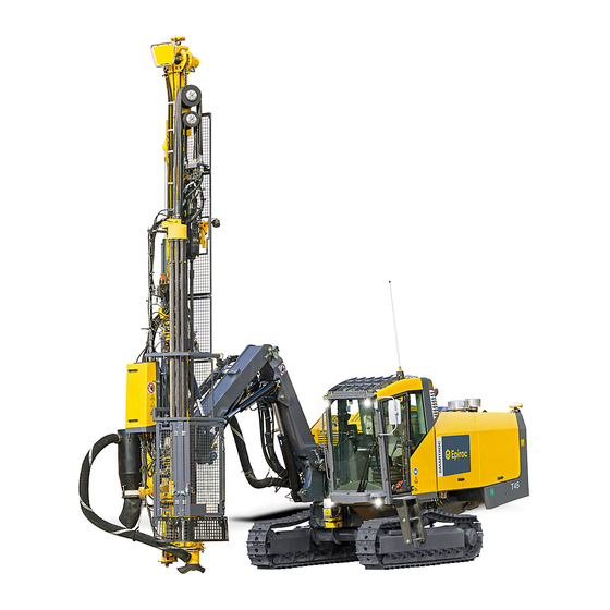
SmartROC T45-11 2 Product Description 2.3 Main Components Main Components Feed Rod Handling System (RHS) Drill support Boom Crawler tracks Dust Collector (DCT) Intercooler and radiator Compressor and hydraulic oil cooler Compressor Diesel engine Hydraulic pumps... -
Page 9: Data Plate
SmartROC T45-11 2 Product Description Operator's cabin Operator's panel 2.4 Data Plate Data Plate The data plate contains the serial number (product identification number) for each individ ual machine, and is required when: Contacting Atlas Copco for support Ordering components or kits Creating records Maintaining records... - Page 10 SmartROC T45-11 2 Product Description...
-
Page 11: Controls And Instruments
SmartROC T45-11 3 Controls and Instruments 3 Controls and Instruments Overview Left lever Right lever Right control panel Operator's environment control panel Winch control unit... -
Page 12: Operating Controls
SmartROC T45-11 3 Controls and Instruments 3.1 Operating Controls Operating Panel Mode selector Positioning mode Drill mode Tram mode Winch mode/Remote control mode Flush air Water mist Dust Collector (DCT) Tramming levers Track oscillation levers Display Escape button Display Toggle button Display Navigation knob Signal Horn Preheating (hydraulic oil) Jack in Jack out... -
Page 13: Right Control Panel
SmartROC T45-11 3 Controls and Instruments 3.2 Right Control Panel Right Control Panel Diesel engine start/stop button Rotation control Value adjustment for buttons B, F, G, and H Automatic rod handling Dust collector Percussion control Feed control Tramming low speed/high speed Track oscillation lock Activation of compressor and/or hydraulics for grinding Automatic thread lubrication Thread lubrication Ignition key/CAN system start USB port... -
Page 14: Left Lever In Tram Mode/Positioning Mode
SmartROC T45-11 3 Controls and Instruments 3.3 Left Lever in Tram Mode/Positioning Mode Left Lever in Tram Mode/Positioning Mode Feed tilt forward Feed tilt backward Feed swing left Feed swing right Feed extension up Feed extension down Semiauto positioning... -
Page 15: Left Lever In Drill Mode
SmartROC T45-11 3 Controls and Instruments 3.4 Left Lever in Drill Mode Left Lever in Drill Mode Rod to carousel Rod to drill center/Hard grip (when rod is in drill center) Rotate carousel (clockwise) Rotate carousel (counterclockwise) Upper drill steel support Lower drill steel support Close drill steel support press and hold button for drill steel support Open drill steel support press and hold button for drill steel support Suction hood Up Suction hood Down Press and hold button both levers work as during positioning mode Press and hold button Open gripper... -
Page 16: Right Lever In Tram Mode/Positioning Mode
SmartROC T45-11 3 Controls and Instruments 3.5 Right Lever in Tram Mode/Positioning Mode Right Lever in Tram Mode/Positioning Mode Boom lowering Boom lift Boom swing left Boom swing right Boom extension out Boom extension in Confirm suggested hole HNS system... -
Page 17: Right Lever In Drill Mode
SmartROC T45-11 3 Controls and Instruments 3.6 Right Lever in Drill Mode Right Lever in Drill Mode Rapidfeed forward Rapidfeed backward Rotation (counterclockwise) and flush air Rotation (clockwise) Reduced autodrilling Full autodrilling Threading Unthreading High percussion Low percussion Resetting of depth meter Retraction Manual flush air... - Page 18 SmartROC T45-11 3 Controls and Instruments Drill stop Proportional Function for Right Lever in Drill Mode Rotation Feed Sector A has a proportional function for rotation and feed. High Percussion and Low Percussion during Collaring and Fulldrilling Deactivates drilling during collaring (low percussion, low rotation, low feed). Does not deacti vate flush air. Activates collaring during fulldrilling (low percussion, low rotation, low flush air, low feed). Activates fulldrilling during collaring (high percussion, high rotation, high flush air, low feed). Deactivates drilling during fulldrilling (percussion, rotation, feed). Does not deactivate flush air.
-
Page 19: Tramming Levers
SmartROC T45-11 3 Controls and Instruments 3.7 Tramming Levers Tramming Controls Forward Neutral Reverse... -
Page 20: Operator's Environment Control Panel
SmartROC T45-11 3 Controls and Instruments 3.8 Operator's Environment Control Panel Panel for Operator's Cabin Front cabin working lights Rear cabin working lights Feed working lights Engine compartment light Upper windshield washers Upper windshield wiper (each press increases speed) - Page 21 SmartROC T45-11 3 Controls and Instruments Upper windshield wiper (each press reduces speed) switch off by pressing and holding the button for 2 seconds Front windshield washer Front windshield wiper (each press reduces speed) switch off by pressing and holding the but ton for 2 seconds Front windshield wiper (each press increases speed) Right windshield wiper (each press reduces speed) switch off by pressing and holding the but ton for 2 seconds Right windshield wiper (each press increases speed) Right windshield washer Air conditioner Air conditioning fan (each press reduces speed) Air conditioning fan (each press increases speed) Temperature (each press reduces temperature) Temperature (each press increases temperature) Heater fan (each press increases speed) Heater fan (each press reduces speed)
-
Page 22: Winch Control Unit
SmartROC T45-11 3 Controls and Instruments 3.9 Winch Control Unit Winch Control Unit Emergency stop Front button, track oscillation up Front button, track oscillation down LED indicates radio contact between winch control unit and receiver unit LED indicates error message LED grip sensor Boom swing, boom lift Track oscillation, right crawler track (up) Track oscillation, right crawler track (down) Track oscillation left crawler track (down) Track oscillation, left crawler track (up) Tramming lever LED indicates low battery LED indicates fully charged battery Front button, increasing winch power Front button, decreasing winch power... - Page 23 SmartROC T45-11 3 Controls and Instruments Cable socket for cable operation without radio contact Cable socket for winch control unit, battery charging cable Winch Control Unit Touch Buttons Cabin/Remote control unit, LED illuminates during winch operation Winch in Winch out Activate winch High speed tramming Low speed tramming Hydraulic jack out Hydraulic jack in Function key Signal horn Winch control unit Off/On...
- Page 24 SmartROC T45-11 3 Controls and Instruments...
-
Page 25: Operation
SmartROC T45-11 4 Operation 4 Operation 4.1 Startup and Shutdown 4.1.1 Turning On Battery Power Condition p Daily maintenance has been carried out. Turn the battery isolation switch a quarter of a turn clockwise until the handle stops. 4.1.2 Turning Off Battery Power The battery isolation switch must be turned off once the diesel engine has stopped, after finishing work, or for longterm storage. Condition p The diesel engine is switched off. Wait 2 minutes after the diesel engine has been switched off. NOTICE Fluid remaining in Hoses after Shutdown Risk of damage to Diesel Exhaust Fluid (DEF) system. Always wait 2 minutes after the engine has shutdown before turning off the battery isolation switch. Turn the battery isolation switch a quarter of a turn counterclockwise until the handle stops. -
Page 26: Starting The Diesel Engine
SmartROC T45-11 4 Operation 4.1.3 Starting the Diesel Engine NOTE: Monitor the display during operation of the machine. Condition p The battery isolation switch is set to ON. p No emergency stop is activated. Turn the ignition key (B) to the ignition position to activate the control system. Wait about one minute. Press the Reset button in the cabin. è A green circle around the start button (C) shows that the ignition is switched on. NOTE: If the green circle flashes, the system is not ready for the engine to start. Wait until the green circle is lit steady. If it continues to flash, check which symbols are shown on the display and correct the error. Press the escape button (A) to reset startup messages. Press and hold the start button (C) for the diesel engine. Release the button when the diesel engine starts. NOTE: If the engine fails to start, stop trying after 20 seconds and wait one minute before trying again. Check the hydraulic oil temperature. If the hydraulic oil temperature is below 20ºC (68ºF), drilling does not work. -
Page 27: Warming Up The System
SmartROC T45-11 4 Operation 4.1.4 Warming Up the System When working in a cold climate, it is important to: Use the preheating function Use ISO VG 32 hydraulic oil Open the recirculation valve when starting These functions prevent preheating and the heating is stopped automatically: Drilling Rotation Tramming Activating Cylinder Functions during Preheating It is recommended to activate the cylinder functions in cold climate. Condition p Preheating is active. Position the boom and feeder. Start rod handling and track oscillation to activate cylin der functions. è Activation of cylinder functions warms the oil in the system. Run rotation for one minute. è Cold oil in the rotation circuit is changed. Rotation prevents preheating and the heating is stopped. Preheating starts automatically after rotation. Heat the oil until the temperature of the hydraulic oil is above 21°. Automatic Preheating Automatic preheating is activated from the control system menu Settings, Rig. The activa tion is set to zero when the control system is restarted and needs reactivation. Automatic preheating warms the hydraulic oil when the oil temperature falls below 20º, min. temperature for heating in a situation which allows preheating. The preheating con tinues until max. temperature for heating is reached. After drilling, rotation, and tramming preheating starts automatically. Manual Preheating Manual preheating is activated on the panel located by the righthand lever. Manual preheating is applied when the hydraulic oil temperature is below min. tempera ture for heating. The mode selector must be in tram mode, drill mode, or positioning mode. -
Page 28: Particle Filter Regeneration
SmartROC T45-11 4 Operation ReCirculation Valve for Preheating ReCirculation valve for preheating There is a recirculation valve under the front hatch on the lefthand side of the rig. When the temperature is below 0° the rig must be started with the recirculation valve open. When the rig has reached operating temperature the recirculation valve must be closed. The recirculation valve must be closed in order for drilling to work. 4.1.5 Particle Filter Regeneration Regeneration cleanses the particle filter of the exhaust system. In normal conditions, re generation starts automatically and does not affect the performance of the machine. WARNING Very High Exhaust Temperatures Can cause serious personal injury and damage to property. Park the machine in the open air during regeneration. Never cover the particle filter. Never let flammable materials come in contact with the particle filter. When regeneration is in progress, the symbol High Exhaust Temperature is shown as a warning in the menu status bar. Symbol Indicating that Forced Regeneration is Required When the symbol for forced regeneration is shown in the menu status bar, a forced regen eration must be started. The remaining hours until the next automatic regeneration is shown in menu Engine. This symbol appears when the counter showing hours to next regeneration indicates zero and a forced regeneration is required. -
Page 29: Delayed Engine Shutdown
SmartROC T45-11 4 Operation If automatic regeneration is blocked when the warning is shown, the machine must be moved to a safe place before activating the forced regeneration. To make conditions more favourable for the regeneration to start, idling mode is recom mended. Time Remaining until next Automatic Regeneration The remaining hours until the next automatic regeneration is shown in menu Engine. The number of hours indicated is an approximation. The regeneration process can be started several hours before the time shown. Blocked Automatic Regeneration Automatic regeneration can be blocked temporarily, for example: Exhaust venting equipment is fitted on the rig in connection with repairs. Personnel need to be on the superstructure of the rig with the diesel engine started. Vegetation or other flammable materials are near the exhaust gases. Automatic regeneration can only be blocked when the diesel engine is started. Blocked re generation is automatically reset when the ignition is switched off/on. Automatic regeneration is blocked in menu Engine. Forced Regeneration Forced regeneration can only be started when there is less than eight hours remaining until next automatic generation. A forced regeneration can be started for two reasons: The warning symbol is shown in the menu status bar. When this symbol is shown in the menu, forced regeneration must be started. The machine will soon be working in a location that is not safe for regeneration, requir ing a forced regeneration to be performed directly. 4.1.6 Delayed Engine Shutdown When the engine is switched off, it may continue to run at idling speed for a few minutes. The delayed engine shutdown (DES) time varies between 1 and 7 minutes. DES is intended to enable the diesel exhaust fluid (DEF) injection system to cool down be fore the engine stops. This reduces the risk of damage to the DEF injector. Testing Emergency Stops on Machines Equipped with DEF injection system The emergency stop system should be tested prior to each shift by activating each emer gency stop button. If the engine is hot, there is a risk of damaging the DEF injector. In such cases, the engine must be restarted immediately after each emergency stop button has been pressed. -
Page 30: Stopping The Diesel Engine
SmartROC T45-11 4 Operation Dialogue Box for Delayed Engine Shutdown NOTICE Increased Wear Risk of damage to diesel exhaust fluid injector. Do not bypass the delayed engine shutdown period. When there is a requirement for the engine to run at idling speed, a dialogue box is shown in the control system. It is always recommended to wait until the engine is turned off auto matically. If Force engine shutdown is selected, DES is bypassed and the engine is switched off immediately. Repeatedly bypassing DES of the engine damages the DEF in jector. Each bypass of DES is recorded in the event log in the rig control system and the diesel engine ECM. 4.1.7 Stopping the Diesel Engine Set the mode selector (A) in tram mode Run the engine at idling speed for 2 minutes. Press the stop button (C) to switch off the diesel engine. NOTICE Increased Wear Risk of damage to diesel exhaust fluid injector. Do not bypass the delayed engine shutdown period. è The engine may continue to run at idling speed for a 17 minutes. Turn the ignition key (B) to "OFF" position after the engine has stopped. -
Page 31: Activating The Winch Control Unit
SmartROC T45-11 4 Operation Wait 2 minutes before turning off the battery isolation switch. NOTICE Fluid remaining in Hoses after Shutdown Risk of damage to Diesel Exhaust Fluid (DEF) system. Always wait 2 minutes after the engine has shutdown before turning off the battery isolation switch. 4.1.8 Activating the Winch Control Unit WARNING Unintentional Maneuvering Can cause serious injury and damage to property. Always have an overview of the drill rig and the winch control unit. Never operate the winch control unit from the drill rig when the winch is being used. Always deactivate the winch control unit when not in use. Set the mode selector on the operation panel in the remote mode Press and hold the ON button on the winch control unit until the indication lights flash once. Press the button for cabin/remote control unit on the winch control unit. è The indicator light comes on when the winch control unit and the receiver unit on the drill rig have radio contact. 4.1.9 Deactivating the Winch Control Unit WARNING Unintentional Maneuvering Can cause serious injury and damage to property. Always have an overview of the drill rig and the winch control unit. Never operate the winch control unit from the drill rig when the winch is being used. Always deactivate the winch control unit when not in use. Press the button for cabin/remote control unit on the winch control unit. è The indicator light goes off. Press the OFF button to switch off the winch control unit. -
Page 32: Tramming
SmartROC T45-11 4 Operation Set the mode selector on the operation panel to drill mode, tram mode, or positioning mode to activate desired functions. 4.2 Tramming 4.2.1 Preparations Before Tramming Perform a walkaround inspection of the machine. Start the diesel engine. Set the boom and feed to the correct position for tramming. Correct Position for Tramming Correct Position for Tramming Direct the boom system straight ahead, and contract the boom and position the feed against the outer boom before opening the track oscillation lock. -
Page 33: Basic Tramming
SmartROC T45-11 4 Operation 4.2.2 Basic Tramming WARNING Tipping Risk The tipping over of a machine can cause serious injury or death. Always wear a seat belt when operating the machine. Always check the ground conditions where the machine will be operated. Never exceed the maximum allowed inclination angles for the machine. Never combine inclination angles for downward/upward/lateral tramming. Adapt the speed to the terrain. WARNING High Voltage Highvoltage cables can cause serious injury and damage to property. Keep away from highvoltage cables. Condition p The diesel engine is started. p The boom and feed are set in the correct position for tramming. p No person is present in the machine's direction of tramming. Set the mode selector (A) to tram mode . Raise the hydraulic jack (B). Unlock track oscillation (E). è The LED goes off when track oscillation is unlocked. Use track oscillation (F) to correct the position of the rig to as horizontal as possible. Select high speed or low speed (D) depending on terrain characteristics. -
Page 34: Tramming On Level Ground
SmartROC T45-11 4 Operation è The LED comes on when low speed is selected. NOTE: The maximum speed for tramming (high speed/low speed) can only be adjusted with the knob (C), when tram ming levers are activated. Operate the tramming levers (G) to move the drill rig in the desired direction. NOTICE Unnecessary stresses Can cause damage to crawler tracks Never operate one crawler track when the other crawler track is sta tionary. Use the boom system to optimize the stability of the drill rig. 4.2.3 Tramming on Level Ground Correct and Incorrect Position when Tramming on Level Ground... -
Page 35: Tramming Uphill
SmartROC T45-11 4 Operation 4.2.4 Tramming Uphill Correct and Incorrect Position for Tramming Uphill Extend the boom system and use it as a counterweight when tramming uphill. 4.2.5 Tramming Downhill Correct and Incorrect Position for Tramming Downhill Retract the boom system maximally towards the drill rig. -
Page 36: Tramming On Sideway Slopes
SmartROC T45-11 4 Operation 4.2.6 Tramming on Sideway Slopes WARNING Increased Risk of Slipping Can cause serious injury or death Be aware of that the risk of slipping is highest when tramming on a sideway slope. Always observe ground conditions. Correct and Incorrect Position for Tramming on Sideway Slopes Use the boom system as a counterweight when tramming on sideway slopes. 4.2.7 Checking before Using the Winch The following must be checked before each use of the winch. Check that the cable (A) is attached correctly in the connector sleeve and eye. The cable must run in line with the eye on the connector sleeve. Check that the cable has not sustained any damage. Check that there are at least 4 turns remaining on the drum. The winch must never be used with fewer than 4 turns remaining on the drum. -
Page 37: Using The Winch When Tramming
SmartROC T45-11 4 Operation 4.2.8 Using the Winch when Tramming WARNING Tipping Risk The tipping over of a machine can cause serious injury or death. Never exceed the maximum allowed inclination angles for the machine. Never combine inclination angles for downward/upward/lateral tramming. Never operate the drill rig from the down side. Keep the winch cable continuously taut. WARNING Unintentional Maneuvering Can cause serious injury and damage to property. Always have an overview of the drill rig and the winch control unit. Never operate the winch control unit from the drill rig when the winch is being used. Always deactivate the winch control unit when not in use. Condition p Checks before using the winch have been performed. Check that the track oscillation is unlocked. Check that the boom system is in transport position. Put the winch disengagement switch in the unlocked position to disengage the winch drum. Pull out the cable and attach the eyelet to the anchorage point. WARNING Tipping Risk The tipping over of a machine can cause serious injury or death. The anchorage point must be firm and secure. Pay attention to local regulations. Never use a damaged cable or hook. The safety hook must not be able to slide or detach from the an chorage point. -
Page 38: Checking After Tramming
SmartROC T45-11 4 Operation Put the winch disengagement switch in the locked position. Set the winch pressure regulator to the desired pressure with the finger switches on the winch control unit. Activate the winch circuit on the winch control unit. Activate winch powerin manually to ensure that the locking mechanism engages fully with the drum before putting a load on the winch. Reverse up/tram down the incline using the tramming levers. Make sure that the ca ble is kept taut constantly. Adjust the pressure for the winch motor to achieve sufficient traction. 4.2.9 Checking after Tramming All emergency stops must be checked for proper function after tramming. 4.3 Positioning 4.3.1 System Settings Setting Desired Feed Angle with the Aiming Device When vertical holes are drilled, the aiming device is not in use and the desired angle set tings must be adjusted to zero. When inclined holes are drilled, the aiming device should be used to ensure that all the holes are drilled with correct angles in the same direction. Adjust the aiming device as parallel as possible to the direction of the blast. If step 1 can’t be followed, set up the feed using a spirit level or similar and con tinue with step 3. Position the feed to the correct side and tilt angles, looking at the actual angles in the Angle Indication menu. Align the aiming device with a reference point as far ahead as possible. è The actual tilt angle and side angle will change. Set the desired angles to the same values as the actual angles. These values are dif ferent from the adjusted angles in step 2. è The graphic image for angle deviations should now display a dot. Turn the aiming device to the same reference point before positioning the feed for the next hole to drill. Adjust the feed until the graphic display shows a dot and it's parallel with the first hole. - Page 39 SmartROC T45-11 4 Operation Activating the Laser Plane Instrument When the drill steel length is replaced or when TAC tube is used, the value for Dist. laser sensor to drill bit must be adjusted. If several laser planes are used, the Dist. to refer ence laser plane, must be set. The reference plane is the top laser plane. Activate laser plane by selecting the box and press Enter in menu Settings, System. Check that the value for Dist. laser sensor to drill bit is correct. è Once the laser receiver has registered the laser plane, the laser plane symbol will change color from grey to green in the menu status bar. The drilled length value will be calculated from the laser plane level. Activating the GPS Compass If the rig is equipped with a GPS compass, it will be activated on machine startup. Deactivate/activate the function in the Rig Options menu. GPS Reception After starting up the rig it may take several minutes before the symbol becomes green. The antennas have to establish contact with the satellites. If the symbol does not become green this may be due to the following causes: No satellites are available. The antennas are covered by snow. There is an open circuit in the cable between the antennas and the electronic unit. If there is no GPS reception, the GPS compass can be deactivated in the Rig Options menu, and the aiming device used in the traditional way. Activating the Drill Plan Handling If the rig is equipped with drill plan handling (Hole navigation), this function will be acti vated on machine startup. Deactivate/activate the function in the Rig Options menu. Calibrating the Coverage Area The coverage area must be calibrated before starting working with drill plans. The cover age area is used in the Navigation menu for viewing which holes can be reached from the current position. Place the rig on a level surface. Set the rig in level position using track oscillation. Lock track oscillation. Go to menu Settings / Navigation and select Calibration Coverage Area. Position the boom system max left and as far forward as possible with vertical feed and feed extension max up. Press Box 1.
- Page 40 SmartROC T45-11 4 Operation Position the boom system max right and as far forward as possible with vertical feed and feed extension max up. Press Box 3. Position the boom system max right and as close to the rig as possible with vertical feed and feed extension max up. Press Box 4. Position the boom system straight forward and as close to the rig as possible with ver tical feed and feed extension max up. Press Box 5. Position the boom system max left and as close to the rig as possible with vertical feed and feed extension max up. Press Box 6. Result è The coverage area of the boom system is shown on the display. Loading Drill Plans Insert a USB memory stick with drill plans into the USB socket. Download drill plans to the rig from the Drillplan menu, or from the Data menu. Selecting Drill Plan Condition p A drill plan is downloaded to the system. Go to the Angle Indication menu or to the Navigation menu. Select Drillplan and press Enter. Select Load Drillplan and press Enter. Go to desired drill plan and press Enter. è Drill plan loading is finished when the message Load OK is shown on the dis play.
-
Page 41: Machine Positioning
SmartROC T45-11 4 Operation 4.3.2 Machine Positioning WARNING Tipping Risk The tipping over of a machine can cause serious injury or death. Always wear a seat belt when operating the machine. Always check the ground conditions where the machine will be operated. Never exceed the maximum allowed inclination angles for the machine. Never combine inclination angles for downward/upward/lateral setup. Set the mode selector (A) to tram mode . Use track oscillation (D) to correct the position of the rig to as horizontal as possible. The track oscillation (C) is unlocked. Lower the jack (B) steadily against the ground without lifting the track frames from the ground. The rear sections of the track frames must stand firmly on the ground. Lock track oscillation (C). è The light comes on when the track oscillation is locked. Position the boom and feed correctly for drilling. Set the feed dowel steadily against the ground with feed extension. - Page 42 SmartROC T45-11 4 Operation Setup on Level Ground Correct and Incorrect Setup Uphill Setup Set the drill rig as close to the horizontal position as possible. Correct and Incorrect Uphill Setup Downhill Setup Set the drill rig as close to the horizontal position as possible. Correct and Incorrect Downhill Setup...
-
Page 43: Drill System Positioning
SmartROC T45-11 4 Operation Setup on Sideway Slopes WARNING Increased Risk of Slipping Can cause serious injury or death Be aware of that the risk of slipping is highest when setting up the rig on a sideway slope. Always observe ground conditions. Always use smooth movements during setup. Always be very careful when setting up the rig on a sideway slope. 4.3.3 Drill System Positioning Positioning with GPS Compass Turn the aiming device to the required direction. Go to the Angle Indication menu. The compass direction setting is visible in the field. Lock the aiming direction value by selecting the arrow. è The value selected to be locked is now visible in the field. The aiming direc tion remains the same until the operator selects a new direction. Positioning with SemiAuto Positioning Function Semiauto positioning: The feed is automatically positioned with the same hole angle as the first hole. Set the hole angle of the first hole in the Angle Indication menu. Press the button on the left lever for semiauto positioning before drilling the sec ond hole. è The feed is automatically positioned with the same hole angle as the first hole. Positioning Using Drill Plans Condition p The mode selector is in tram or positioning mode Go to the Navigation menu. Select the first hole to drill in the drill plan and press the button on the right lever. è... - Page 44 SmartROC T45-11 4 Operation Position the rig and boom until the positioning is correct for the first hole. è When the tramming and positioning levers are used, the menu changes to the Navigation menu. The bars in the menu turn green when positioning is correct. Release the semiauto positioning button Set up the rig according to instructions in Machine Positioning. Set the mode selector to drill mode è The menu changes to the Drilling menu. Set the hole depth counter to zero è Hole length and target values from the drill plan are presented in the Drilling menu. Drill the first hole. è The drilling stops when the target is reached. Saving Drill Plan The drill plan must be saved after drilling. Condition p A USB stick is in the USB port. Select Drillplan under Data Save in the Data menu and press Enter to confirm. Select Copy Logs To USB. è The drill plan is saved to the USB stick. Adding a Hole in a Drill Plan Position the drill bit in the intended location of the hole. Go to the Drillplan menu. Select Add hole and press Enter. Confirm the new hole by selecting Add hole if the information for the hole is correct. Deleting a Hole in a Drill Plan Go to the Drillplan menu. Select the hole to delete. Select Delete hole and press Enter.
-
Page 45: Rod Handling
SmartROC T45-11 4 Operation 4.4 Rod Handling 4.4.1 Loading the Rod Carousel WARNING Risk of Clamping or Crushing Can cause serious injury or death. Always use lifting assistance when loading the carousel. Follow the instructions carefully. Two persons are required to load or empty the rod carousel. Condition p Two persons who are trained and well conversant with the equipment are required to fill the drill pipes. p Suitable lifting equipment must be used. Set the mode selector to drill mode . Move the rock drill to its top position on the feeder ... - Page 46 SmartROC T45-11 4 Operation Position the feed beam to horizontal position. Rotate the rod carousel anticlockwise repeatedly until the carousel has reached its end position. Activate the rapid feed stops to obtain the correct stops Run the rock drill down to its lowest position Open both drill steel supports + Insert the first drill rod through the drill steel supports and close the drill steel supports to grip the drill rod + WARNING Moving Parts Can cause serious injury or death Never stand close to the drill rod when closing the drill supports.
- Page 47 SmartROC T45-11 4 Operation Thread the rock drill fully into the drill rod sleeve DANGER Rotating Parts Will cause serious injury or death Never hold the drill rod during rotation. Run the rock drill up with the drill rod until the rock drill stops with the thread inside the upper drillsteel support Open the rod handling grippers and move out the rod handling arms to grip the drill steel + Release the button è The grippers close. Release the left lever to the neutral position. è The grippers adopt loose grip. Run the rock drill up to the position for inserting to carousel Activate hard grip Activate unthreading Insert the drill rod into the carousel when the rock drill has been unthreaded from the drill rod. Rotate the carousel clockwise Open both drill steel supports + Repeat the procedure until the required number of drill rods are in the carousel.
-
Page 48: Drilling
SmartROC T45-11 4 Operation Thread a drill bit onto the last drill pipe to finish the procedure. DANGER Rotating Parts There is a risk of serious injury or death as clothing can get caught in the machine. Stop the drill rotation before adding a drill bit. 4.5 Drilling 4.5.1 Drilling Settings Calibrating the Length Sensor Length Settings Menu The rig is fitted with an absolute position sensor and does not usually need calibration. The length sensor requires calibration in the following cases: Program loading Parameter loading The "Length sensor not calibrated" symbol is shown Change user to service (SE). Reverse the rock drill to the mechanical stop with drill feed or unthreading. -
Page 49: Drill A Hole
SmartROC T45-11 4 Operation Reset the length sensor by pressing the button Reset length sensor Setting the Depth Measuring System Select desired measuring method Hole Length or Hole Depth in the System menu under Settings. Set the desired hole depth in the Drilling menu when using automatic drill stop. Reset the hole depth counter when the drill bit is positioned against the ground. 4.5.2 Drill a Hole Condition p The rock drill is in the upper position. A drill rod is coupled to the rock drill and a drill bit is mounted on to the drill rod. Set the mode selector to drill mode on the operating panel. Make sure that the upper and lower drill steel supports are closed. Lower the drill bit to just above the ground Set the hole depth counter to zero Lower the suction hood to the ground Activate flush air on the operating panel. Activate dust collector on the operating panel. Activate rotation and flush air Activate collaring . Move the lever proportionally forward until the drill bit has en tered into solid rock. -
Page 50: Stop Drilling
SmartROC T45-11 4 Operation Lock collaring. Press the button on the right lever when the lever is in the sec tion. The right lever can be released to neutral position when collaring is locked and the symbol is shown in the status bar. è If collaring is unsuccessful the right lever must be moved back and the collaring process restarted. Activate full drilling after reaching homogenous rock or once the drill bit has entered far enough into the rock. Move the right lever to the position and hold it there for two seconds, or activate the button on right lever. è A green symbol appears on the status bar of the display to indicate that full drilling is activated. 4.5.3 Stop Drilling Press the button to stop ongoing drilling. 4.5.4 Adding Drill Rods Unthreading and Retraction of Rock Drill Condition p The mode selector is in drill mode p The drill rod retraction function is deactivated. Close the upper drill steel support to lock the coupling sleeve + Activate unthreading è The rock drill is unthreaded from the drill rod when the shank adapter is free from the sleeve. - Page 51 SmartROC T45-11 4 Operation Activate rapid feed up è The cradle stops automatically above the carousel so that a new drill rod can be added. Move the right lever to neutral position. Adding a New Drill Rod Condition p The mode selector is in drill mode p A new drill rod is in the RHS grippers. Move the drill rod to drill centre Move the left lever to neutral position. è The grippers adopt loose grip. Activate threading è The rock drill is threaded onto the new drill rod and the new drill rod is threaded to the drill string. Move the right lever to neutral position. Move the rod handling arms to the carousel + . Release the button and the lever.
-
Page 52: Changing A Drill Bit
SmartROC T45-11 4 Operation 4.5.5 Changing a Drill Bit DANGER Rotating Parts There is a risk of serious injury or death as clothing can get caught in the machine. Stop the drill rotation before changing drill bits. NOTICE High Impact Percussion Risk of damage to drill Never start percussion with the drill bit in midair. Move the feed until the feed dowel is approximately 10 cm from the rock. Make sure that drill rotation is stopped. Move the drill bit forward until it is pressed against the rock. Activate high percussion for a few seconds. If the percussion pressure is engaged for too long then the drill steel can detach from the shank adapter. Deactivate high percussion when the drill bit has loosened. Unscrew the old drill bit by hand and replace with a new one. 4.5.6 Checks During Drilling Check point Inspection Instructions Rock drill hydraulic hoses Abnormal vibrations in the hy Check the accumulator. For fur draulic hoses. ther details see the maintenance instructions for the rock drill” Dust collector (DCT) Suction ability and filter cleaning In the event of dust buildup: Check the filter in the filter holder, the suction hose and the drillsteel support gasket. If water flushes out of the hole the dust collector must be switched off. Drill rig Visual check... -
Page 53: In Case Of Breakdown Or Incident
SmartROC T45-11 4 Operation Check point Inspection Instructions Return oil filter Operator's display in cabin Check for any signs of leaks. If the pressure in the return oil filter exceeds the set value, a symbol will be shown on the operator's display. Display for engine and direc Visual check Check that none of the fault indi tional instruments cator symbols is on. If a fault is indicated in the status bar, stop the unit and rectify the fault. Hydraulic system Visual check Monitor all pressure gauges in the Drilling menu. Suction hood Occurrence of crushed rock Raise the suction hood now and then to check that crushed rock is flushed up properly from the hole. 4.5.7 In Case of Breakdown or Incident Checking High Coupling Sleeve Temperature NOTE: Coupling sleeve temperature must not exceed 120ºC (248ºF). Depending on the layers of the rock, temperature can vary even within a small area. High coupling sleeve temperature is usually due to a poor ratio between drill feed pressure, per cussion pressure and rotation pressure. Excessive coupling sleeve temperature is indicated by: Measuring with a thermometer. Oil dripping from the rock drill vaporizing on the coupling sleeve. - Page 54 SmartROC T45-11 4 Operation Difficulties in Loosening the Coupling Sleeve The best method of loosening the coupling sleeve is to “drill” the last few centimetres with out feed pressure and rotation, leaving percussion active for a few seconds to break the coupling sleeve. Make sure the RPCF system is set correctly. An RPCF system that is set too high causes excessive torque in the coupling sleeve. Avoiding Hole Deflection Drill with as low drill feed pressure as possible. Check the condition of the drill bit. Use TAC tubes, drop center bits. Drill the first drill steel with reduced drilling for at least half of the drill steel in order to minimize hole deflection at the start of the hole.
-
Page 55: Transport
SmartROC T45-11 5 Transport 5 Transport 5.1 Preparations Before Hoisting WARNING Risk of Crushing Crushing can cause serious personal injury or death. Use extreme caution when slinging and hoisting heavy objects. Hoisting must take place at the center of gravity. Only use slings that are intact and designed for the load they shall carry. Fasten the straps to lifting eyes, when available. Do not go near a suspended load. Before transporting in shafts or similar, it may be necessary to fully or partially dismantle the machine. Observe the following when dismantling, hoisting and assembling: Clean the entire machine with water and/or detergent containing a grease solvent be fore dismantling. Mark hoses, pipes and other connections to make reassembly easier and prevent mix ups. Make sure that everything is clean when dismantling hydraulic, compressed air and water flushing hoses. Immediately plug all hoses, nipples and hydraulic oil pipes, or seal. 5.2 Before Loading the Machine onto the Transport Vehicle WARNING Tipping Risk The tipping over of a machine can cause serious injury or death. Lock the track oscillation before hoisting the machine. Adapt transportation equipment to the dimensions and weight of the machine. Check that all hatches are properly locked. Run the rock drill to the lowest position. Use the boom and feed controls alternately to bring the feed down into the horizontal trans port position. -
Page 56: Hoisting A Drill Rig
SmartROC T45-11 5 Transport 5.3 Hoisting a Drill Rig WARNING Risk of Crushing Crushing can cause serious personal injury or death. Use extreme caution when slinging and hoisting heavy objects. Hoisting must take place at the center of gravity. Only use slings that are intact and designed for the load they will carry. Fasten the straps to lifting eyes, if available. Do not approach a suspended load.. To achieve maximum drill rig stability, position the boom, feed, and rock drill: Boom lift cylinder maximum OUT. Boom extension maximum IN. Feed dump cylinder maximum OUT (make sure that the feed does not collide with the lifting equipment). Rock drill in END POSITION (lower position). Make sure that the hydraulic jack is retracted. Track oscillation cylinders to LOCKED position. Make sure that none of the hoses, controls, or any other components can get caught or sustain damage when the hoisting slings are tensioned and under load. Place the hoisting slings at designated points under both crawler tracks. Make sure the chassis is not damaged when positioning the feed in the transport/ hoisting position. -
Page 57: Before Transporting The Loaded Drill Rig
SmartROC T45-11 5 Transport 5.4 Before Transporting the Loaded Drill Rig WARNING Tipping Risk The tipping over of a machine can cause serious injury or death. Lock the track oscillation before hoisting the machine. Adapt transportation equipment to the dimensions and weight of the machine. Check that all hatches are properly locked. Transport Position Condition p Attach straps or chains to the lifting eyes on the machine and transport vehicle. Extract the hydraulic jack. Track oscillation cylinders to LOCKED position. Support the feed beam against the vehicle to prevent overloading. Switch off the diesel engine. Strap the drill rig securely to the vehicle. - Page 58 SmartROC T45-11 5 Transport...
-
Page 59: Daily Maintenance
SmartROC T45-11 6 Daily Maintenance 6 Daily Maintenance 6.1 Maintenance Table Additional information Visual Check Wash Machine Externally Check Lubrication Oil Level Tank Drain Condensate in Pressure Tank Check Fire Extinguishers Check Emergency Stops and Work Lights Check Coolant Level Check Track Frames 6.10 Check Motor Oil Level 6.11 Check Diesel Engine and Compressor 6.12 Check Hydraulic Tank 6.13 Drain PreFilter 6.14 Check Compressor Oil Level 6.15 Check Condition of CLS Pump 6.16 Check Winch 6.17 Check Small Remote Control 1 Operating Personnel 6.2 Visual Check Before each shift starts, an extra and thorough visual safety check should be performed in order to detect: Damage that could give rise to structural weakness or cracks... - Page 60 SmartROC T45-11 6 Daily Maintenance Cracks of fractures in materials or welded joints Check Points Operator's cabin with brackets Cylinder brackets Feed holder with brackets Feed chain with brackets Hose drum with cradle Yoke for drill rods Boom head Boom Boom support with pivot Track frames with attachment Winch with brackets (option) Winch cable with eyelet (option)
-
Page 61: Wash Machine Externally
SmartROC T45-11 6 Daily Maintenance 6.3 Wash Machine Externally Rinse the machine with water at least once a day to remove drill cuttings, mud, and dirt. The feed, front part of the boom, and track frames are particularly important to keep clean. 6.4 Check Lubrication Oil Level Tank The lubricating oil tank is mounted on the left side of the machine frame. Check the tank and connections for signs of leakage. Make sure the lubrication oil level is above the top sight glass (B). Refill with lubrication oil (A,) if necessary. Always use a funnel with a strainer. NOTE: The lubrication oil level should not be below 40 mm (1.6"). If the lubricating sys tem is completely drained, the system will have to be bled. 6.5 Drain Condensate in Pressure Tank Compressor tank Compressor cooler Compressor element Condition p The machine must have been switched off for at least 1 hour. -
Page 62: Check Fire Extinguishers
SmartROC T45-11 6 Daily Maintenance Drain the condensate from plug 1 at the draining point on the righthand side of the machine. 6.6 Check Fire Extinguishers Check that the indicator is in the green zone. è Replace the fire extinguisher if the indicator is within, or close to, any of the red zones. Check that none of the seals are broken and that services have been performed within the prescribed time. Inspect the complete fire extinguisher and holder for loose parts, defects, or dam ages. -
Page 63: Check Emergency Stops And Work Lights
SmartROC T45-11 6 Daily Maintenance 6.7 Check Emergency Stops and Work Lights Check that each emergency stop (A) stops the engine when activated. Before check ing the next emergency stop, the previous emergency stop must be reset. Check the functionality of the work lights, front and rear (B). -
Page 64: Check Coolant Level
SmartROC T45-11 6 Daily Maintenance 6.8 Check Coolant Level Condition p The coolant level must be checked when the diesel engine is cold. Check the coolant level (B). è The level should be between the upper and lower mark. -
Page 65: Check Track Frames
SmartROC T45-11 6 Daily Maintenance 6.9 Check Track Frames Check for signs of leakage on the traction motor (A). Check for signs of leakage on the traction gears (B). Check for signs of leakage on the carrier roller (C). Check for signs of leakage on the track rollers (D). Visually inspect the tension on the crawler tracks (E). Check that the springs and dampeners move freely on the front wheel (F). Clean, if necessary. Check for loose screws and nuts. -
Page 66: Check Motor Oil Level
SmartROC T45-11 6 Daily Maintenance 6.10 Check Motor Oil Level WARNING Burning Hazard Hot components and surfaces can cause serious injury. Use working gloves and cover your arms with long sleeves. Condition p The diesel engine is off. Check that the oil level is between the upper and lower mark on the dipstick (A). Fill oil through the filler cap (B) if necessary. See reference documentation Diesel engine instruction manual... -
Page 67: Check Diesel Engine And Compressor
SmartROC T45-11 6 Daily Maintenance 6.11 Check Diesel Engine and Compressor Check that the oil level indicator (A) on the compressor is in the green zone. Check for signs of leakage on the hydraulic pumps (B). Check that the diesel engine oil level is between the two marks on the dipstick (C). Check the diesel engine (D) for leaks. -
Page 68: Check Hydraulic Tank
SmartROC T45-11 6 Daily Maintenance 6.12 Check Hydraulic Tank Condition p The machine must be standing on a flat surface to obtain an accurate reading. p The oil temperature should be 40°C (104°F). Replace the return oil filter (A) if the warning sign is displayed. Check the breather filter (B). Check the tank (C) and connections for signs of leakage. Check that the oil level covers the lower sight glass (D) and half of the upper sight glass (E). 6.13 Drain PreFilter Drain water from the prefilter by opening the drain outlet (A). -
Page 69: Check Compressor Oil Level
SmartROC T45-11 6 Daily Maintenance 6.14 Check Compressor Oil Level Make sure the machine is on level ground. Switch off the machine and allow the oil level to settle for at least 5 minutes. Check the compressor oil level. The indicator on the gauge (A) must be in the green zone. Fill with oil at (B), if required. Use the correct amount and oil grade. 6.15 Check Condition of CLS Pump... -
Page 70: Check Winch
SmartROC T45-11 6 Daily Maintenance Check that there is no leakage on the safety valve (A) of the CLS pump. 6.16 Check Winch Check for damage, unwinding, wear, and corrosion on the winch cable (A). Check for damage, cracks, and wear on the hook (B) and check that it is properly mounted. -
Page 71: Check Small Remote Control
SmartROC T45-11 6 Daily Maintenance 6.17 Check Small Remote Control Make sure none of the rubber bellows (A) on the switches/levers of the control unit are damaged... - Page 72 SmartROC T45-11 6 Daily Maintenance...
-
Page 73: Technical Data
SmartROC T45-11 7 Technical Data 7 Technical Data 7.1 Technical Data Weight (Standard Equipment without Drill Steel) SmartROC T4511 Weight 17700 kg Performance Diesel engine, Caterpillar Power output at 1900 rpm 242 kW Temperature range in operation 25° to +50°C Tramming speed, maximum 3.4 km/h Tractive force 112 kN Ground pressure, average 110 kPa Ground clearance 405 mm Maximum hydraulic pressure 280 bar Track oscillation ±10 ° Permitted Inclination Angles on SmartROC T4511 Stability is specified with respect to CE standards stipulating that rigs must not be operated on inclina tions steeper than 20 degrees without the use of a winch. ANGLES MUST NOT BE COMBINED! Maximum permitted inclination Down/Up (lengthways) without 20°/20° angles during tramming: winch Down/Up (lengthways) with 25°/25°... - Page 74 SmartROC T45-11 7 Technical Data Electrical System Voltage 24 V Batteries Voltage 2 * 12 V/185 Ah Working lights Voltage 24 V Luminous flux 3500 lm Alternator Voltage 24V/95 Ah Capacities Hydraulic oil reservoir 100 l Hydraulic systems Total 240 l Fuel tank 400 l Traction gear oil 3 l Compressor oil 52 l Lubricating oil tank 23 l Diesel engine oil 32 l Engine cooling system 75 l Air Conditioning Unit Red Dot Refrigerant, type R134 A...
-
Page 75: Dimensions
SmartROC T45-11 7 Technical Data 7.2 Dimensions Transport Dimensions (mm) Side View (mm) View from Above (mm) - Page 76 SmartROC T45-11 7 Technical Data Vertical Reach (mm) Horizontal Reach (mm)
-
Page 77: Highest Permitted Inclination Angles For Tramming And Drill Rig Setup
SmartROC T45-11 7 Technical Data Feed Swing Angles The machine is equipped to allow both vertical and horizontal drilling without reconnection of the feed beam. 7.3 Highest Permitted Inclination Angles for Tramming and Drill Rig Setup WARNING Tipping Risk The tipping over of a machine can cause serious injury or death. Never exceed the maximum allowed inclination angles for the machine. Never combine inclination angles. -
Page 78: Ordinary Tramming
SmartROC T45-11 7 Technical Data 7.3.1 Ordinary Tramming Tramming Direction Maximum Angle of Inclina tion (°) Forward Reverse Left Right... -
Page 79: Tramming With The Feed In Vertical Position And Centered Between The Track Frames
SmartROC T45-11 7 Technical Data 7.3.2 Tramming with the Feed in Vertical Position and Centered Between the Track Frames Tramming with the Feed in Vertical Position and Centered Between the Track Frames Direction Maximum Angle of Inclina tion (°) Forward Reverse Left Right... -
Page 80: Drill Rig Setup: The Feed In Vertical Position And Centered Between The Track Frames
SmartROC T45-11 7 Technical Data 7.3.3 Drill Rig Setup: the Feed in Vertical Position and Centered Between the Track Frames Drill Rig Setup: the Feed in Vertical Position and Centered Between the Track Frames Direction Maximum Angle of Inclina tion (°) Forward Reverse Left Right... -
Page 81: Drill Rig Setup: The Feed In Vertical Position And The Boom Swung Maximum To The Left
SmartROC T45-11 7 Technical Data 7.3.4 Drill Rig Setup: the Feed in Vertical Position and the Boom Swung Maximum to the Left Drill Rig Setup: the Feed in Vertical Position and the Boom Swung Maximum to the Left Direction Maximum Angle of Inclina tion (°) Forward Reverse Left Right... -
Page 82: Drill Rig Setup: The Feed In Vertical Position And The Boom Swung Maximum To The Right
SmartROC T45-11 7 Technical Data 7.3.5 Drill Rig Setup: the Feed in Vertical Position and the Boom Swung Maximum to the Right Drill Rig Setup: the Feed in Vertical Position and the Boom Swung Maximum to the Right Direction Maximum Angle of Inclina tion (°) Forward Reverse Left Right... -
Page 83: Drill Rig Setup: The Feed Top In Extreme Position Forward, The Feed Laterally Vertical And Centered Between The Track Frames
SmartROC T45-11 7 Technical Data 7.3.6 Drill Rig Setup: the Feed Top in Extreme Position Forward, the Feed Laterally Vertical and Centered Between the Track Frames Drill Rig Setup: the Feed Top in Extreme Position Forward, the Feeder Laterally Vertical and Centered Between the Track Frames Direction Maximum Angle of Inclina tion (°) Forward Reverse Left Right... -
Page 84: Drill Rig Setup: The Feed Top In Extreme Position Forward And To The Left, And With The Boom Swung Maximum To The Left
SmartROC T45-11 7 Technical Data 7.3.7 Drill Rig Setup: the Feed Top in Extreme Position Forward and to the Left, and with the Boom Swung Maximum to the Left Drill Rig Setup: the Feed Top in Extreme Position Forward and to the Left, and with the Boom Swung Maximum to the Left Direction Maximum Angle of Inclina tion (°) Forward Reverse Left Right... -
Page 85: Drill Rig Setup: The Feed Top In Extreme Position Forward And To The Right, And With The Boom Swung Maximum To The Right
SmartROC T45-11 7 Technical Data 7.3.8 Drill Rig Setup: the Feed Top in Extreme Position Forward and to the Right, and with the Boom Swung Maximum to the Right Drill Rig Setup: the Feed Top in Extreme Position Forward and to the Right, and with the Boom Swung Maximum to the Right Direction Maximum Angle of Inclina tion (°) Forward Reverse Left Right... - Page 86 SmartROC T45-11 7 Technical Data...
Need help?
Do you have a question about the SmartROC T45-11 and is the answer not in the manual?
Questions and answers