Table of Contents
Advertisement
Advertisement
Table of Contents

Related Manuals for Atlas Copco Qc4003


Summary of Contents for Atlas Copco Qc4003
- Page 1 Instruction Manual English Transformer Maintenance...
- Page 2 Transformer Maintenance Original instructions Printed matter N° 2954 6170 04 ATLAS COPCO - PORTABLE ENERGY DIVISION www.atlascopco.com 02/2016...
- Page 3 While every effort has been made to ensure that the information in this manual is correct, Atlas Copco does not assume responsibility for possible errors. Copyright 2016, Grupos Electrógenos Europa, S.A.U., Zaragoza, Spain. Any unauthorized use or copying of the contents or any part thereof is prohibited.
-
Page 4: Table Of Contents
Transformer Maintenance Box. While every effort has been made to ensure that the information in this manual is correct, Atlas Copco does not assume responsibility for possible errors. Atlas Copco reserves the right to make changes without prior notice. -
Page 5: Introduction
Take load from the Mains The TM-box is only to be applied together with a To repair or to preform service on a transformer, the Qc4003™. The Qc4003™ is a power management Mains should be disconnected. controller, carrying out generator control, supervision 1. -
Page 6: Safety Precautions
2.4.4 Voltage connection generator’s Qc4003™. This gives the operator the Sufficient care must be taken to protect the terminals against static discharges during the installation. Once possibility to read out the same values from both... -
Page 7: Component Overview
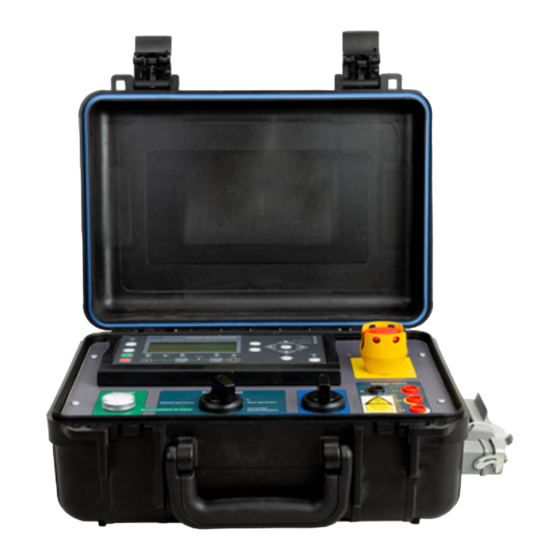
2.4.6 Component overview Display Connect mains lamp Function select switch Power switch Qc4003 Voltage measurement point Shut down Shutdown button U/F OK LED Voltage mains Connect Function select Power mains Stop Deload generator Start generator Generator Synchronisation to mains synchronisation... -
Page 8: Setting Qc4003™ For Transformer Maintenance
Setting Qc4003™ for transformer maintenance 3. Set communication ID: Hardware installation • Press navigation left, up and right button – TM-box together for 3 seconds. – 2 TM cables (one CAN communication cable and Qc4003 • Enter service password. one cable for 230-400V measurement) E N T E R M E N U N O. - Page 9 Setting the TM-box display as primary display 1. Set communication ID: • Press navigation left, up and right button together for 3 seconds. • Enter service password. • Select ‘ID 2’. 2. Set display priority: • Press the “view” button for 2 seconds. •...
-
Page 10: Before Starting
Before starting Following preliminary actions Mains Mains should be carried out before starting Transformer Maintenance! Sensing Sensing 1. Adjust following parameter settings • Parameter 1425: Turn OFF ROCOF. • Parameter 1434: Turn OFF Vector jump. • Parameter 6001/6011: Check Frequency from mains and adjust Nominal setting of the generator towards it. -
Page 11: Transformer Maintenance Procedure
Transformer maintenance procedure OFF status TM-box Connect Function select Power The ‘Function select’ switch is in the OFF position. mains Stop Deload generator Start generator Generator Synchronisation to mains synchronisation Deload mains Island Flow 1. Manually connect the power cables from the generator to the busbar. -
Page 12: Start Generator
Start generator TM-box Connect Function select Power Turn the ‘Function select’ switch to Start generator. mains Stop Deload generator Start generator Generator Synchronisation to mains synchronisation Deload mains Island Flow 1. The generator starts up. 2. When the generator is running (shown on TM-box display), make sure that voltage and frequency are This is indicated by the U/F OK LED (7) on the TM- box display. -
Page 13: Synchronise The Generator
Synchronise the generator TM-box Connect Function select Power Turn the ‘Function select’ switch to Generator mains synchronisation. Stop Deload generator Start generator Generator Synchronisation to mains synchronisation Deload mains Island Flow 1. The generator is forced to make a dynamic synchronisation to the Mains and closes the generator breaker. -
Page 14: Deload Mains
Deload Mains TM-box Connect Function select Power Turn the ‘Function select’ switch to Deload mains for mains load take over. Stop Deload generator Start generator Generator Synchronisation to mains synchronisation Deload mains Island Flow 1. Adjust the generator power by means of the ‘Power switch’. -
Page 15: Island Operation
Island operation TM-box Connect Function select Power Turn the ‘Function select’ switch to Island as quickly as mains Stop possible to prevent frequency variation due to load Deload generator changes. Start generator Generator Synchronisation to mains synchronisation Deload mains Island Flow 1. -
Page 16: Back Synchronisation To The Mains
Back synchronisation to the Mains Flow Connect the voltage measurement line between the TM- box and the mains connection point (fuses/breaker). Do not forget to check the phase sequence of these measuring cables. See also section 6 for the difference between three phase and single phase measurement. -
Page 17: Manually Restore Fuses
Manually restore fuses TM-box Connect When the synchroscope in the display is stable at 12 Function select Power mains o'clock, the Connect mains lamp will light up and a Stop buzzer will be activated. Deload generator Start generator Generator Synchronisation to mains synchronisation Deload mains Island... -
Page 18: Deload The Generator
Deload the generator TM-box Turn the ‘Function select’ switch to Deload generator. Connect Function select Power mains Stop Deload generator Start generator Generator Synchronisation to mains synchronisation Deload mains Island Flow The generator deloads and opens the generator breaker. The speed of deload can be selected in parameter 2620 where the ramp down %/s can be adjusted. -
Page 19: Stop The Generator
Stop the generator TM-box Turn the ‘Function select’ switch to Stop to stop the Connect Function select Power mains generator. Stop Deload generator Start generator Generator Synchronisation to mains synchronisation Deload mains Island Flow 1. After the cooldown time, set by the operator, the generator will stop automatically. -
Page 20: Settings To Increase Stability
5.10 Settings to increase stability 5.10.1 PID regulation To fine-tune synchronisation when switching back to the Mains, it is recommended to adjust PID regulation. To improve stability of the active power regulation following parameters can be used/adjusted: 2530 Power PID 2531 Kp Proportional 2532... -
Page 21: Power Factor Settings
5.10.2 Power factor settings To approach the actual power factor measured at the Mains as close as possible, adjust parameters 7051 and 7052. Parameter 7051 will be adjusted by the power button on the TM-box, so no adjustments are to be made on the display Parameter 7052 is to be set equally to the measured mains power factor. -
Page 22: Voltage Mains Measurement
This can only be done if the neutral of the generator When all three phases are used to measure the and the transformer are correctly connected, so the voltage, the Qc4003™ will automatically run a phase common measurement point is the same. sequence check. -
Page 23: Cable And Plug Connection
10A-M 16A 250V QV3 remove the box without stopping the generator. Or it could function as a kind of access lock of the system. Cable specifications The connection between the generator’s Qc4003™ and Signal Pin no. Cable wire Qc4003™ the TM-box is split into two cables: one CAN Harting (colour/no.) - Page 25 www.atlascopco.com...
Need help?
Do you have a question about the Qc4003 and is the answer not in the manual?
Questions and answers