AERMEC VED Series Use And Installation Manual
Fan coil for horizontal and vertical ducted installation
Hide thumbs
Also See for VED Series:
- Technical manual (77 pages) ,
- Installation manual (52 pages) ,
- Use and installation manual (56 pages)
Table of Contents
Advertisement
Available languages
Available languages
Quick Links
VENTILCONVETTORE
PER INSTALLAZIONE CANALIZZATA, ORIZZONTALE E VERTICALE
FAN COIL
FOR HORIZONTAL AND VERTICAL DUCTED INSTALLATION
VENTILO-CONVECTEUR
POUR INSTALLATION CANALISÉE, HORIZONTALE ET VERTICALE
GEBLÄSEKONVEKTOR
FÜR KANAL-, HORIZONTAL- UND VERTIKALEINBAU
FAN COIL
PARA INSTALACIÓN CANALIZADA, HORIZONTAL Y VERTICAL
VED
VED 430
VED 440
VED 530
VED 540
VED 630
VED 640
VED 730
VED 740
M A N U A L E
D ' U S O
U S E
A N D
I N S T A L L A T I O N
M A N U E L D ' U T I L I S AT I O N E T D ' I N S TA L L AT I O N
BEDIENUNGS- UND INSTALLATIONSANLEITUNG
M A N UA L D E I N S T R U C C I O N E S E I N S TA L AC I Ó N
VED 432
VED 441
VED 532
VED 541
VED 632
VED 641
VED 732
VED 731
E
I N S T A L L A Z I O N E
M A N U A L
IVEDLJ 1107 - 4880900_01
Sostituisce il: 1011 - 4880900_00
Advertisement
Table of Contents

Related Manuals for AERMEC VED Series


Summary of Contents for AERMEC VED Series
- Page 1 M A N U A L E D ’ U S O I N S T A L L A Z I O N E U S E A N D I N S T A L L A T I O N M A N U A L M A N U E L D ’...
- Page 2 INDICE OSSERVAZIONI REMARKS REMARQUES HINWISE OBSERVACIONES DICHIARAZIONE DI CONFORMITÀ DECLARATION OF CONFORMITY DÉCLARATION DE CONFORMITÉ KONFORMITÄTSERKLÄRUNG DECLARACIÓN DE CONFORMIDAD TRASPORTO • SIMBOLI DI SICUREZZA CARRIAGE • SAFETY SYMBOL TRANSPORT • SIMBOLESES DE SECURITE TRANSPORT • SICHERHEITSSYMBOLE TRANSPORTE • SÍMBOLOS DE SEGURIDAD Italiano English Français...
- Page 3 Nel quadro di una politica di miglioramento to, per almeno 10 anni per eventuali riferimenti futuri. La garanzia dell'apparecchio non copre in ogni continuo del prodotto, AERMEC S.p.A. si riser- Leggere attentamente e completamente tutte le caso i costi dovuti ad autoscale, ponteggi o altri va la facoltà...
-
Page 4: Dichiarazione Di Conformità
VED PLUS ACCESSOIRES Falls das Gerät mit Zubehörteilen ausgerüstet wird, die nicht von Il est interdit de faire fonctionner l'appareil avec des accessoires qui ne Aermec geliefert werden, ist dessen Inbetriebnahme solange untersagt. sont pas fournis de Aermec. DECLARACIÓN DE CONFORMIDAD Los que suscriben la presente declaran bajo la propia y exclusiva responsabilidad que el conjunto en objeto, defi... - Page 5 TRASPORTO • CARRIAGE • TRANSPORT • TRANSPORT • TRANSPORTE NON bagnare. Tenere al riparo NON calpestare dalla pioggia Do NOT step Do NOT wet NE PAS marcher sur cet emballage CRAINT l’humidité Nicht betreten Vor Nässe schützen NO pisar NO mojar Sovrapponibilità: controllare sull’imballo per conoscere il numero di macchine impilabili Stacking: control the packing to know the number of machines that can be stacked Empilement: vérifier sur l’emballage pour connaître le nombre d’appareils pouvant être empilés...
- Page 6 Realizzato con materiali di qualità superiore, nel rigoroso rispetto delle normative di sicurezza, VED è di facile utilizzo e vi accompagnerà a lungo nell'uso. La serie di ventilconvettori VED è progettata per essere integrata nel sistema VMF. VMF (Variable Multi Flow) è il sistema in grado di gestire in modo intelligente un impianto idronico completo, composto quindi da un chiller/pompa di calore, una caldaia, una rete di ventilconvettori (plurivelocità...
- Page 7 INFORMAZIONI IMPORTANTI E MANUTENZIONE ATTENZIONE: il ventilconvettore è massimo a 40 °C. Non usare prodotti Durante il funzionamento si potrebbero collegato alla rete elettrica ed al chimici o solventi per nessuna parte avvertire rumori e scricchiolii interni circuito idraulico, un intervento da del ventilconvettore.
-
Page 8: Esempi Di Impianto
DESCRIZIONE DELL’UNITÀ SCOPO DEI VENTILCONVETTORI VED Il ventilconvettore è un terminale per il trattamento dell’aria di un ambiente sia nella stagione invernale sia in quella estiva. I ventilconvettori VED, sono concepiti per adattarsi a qualsiasi esigenza negli impianti di tipo canalizzato. In particolare la possibilità... -
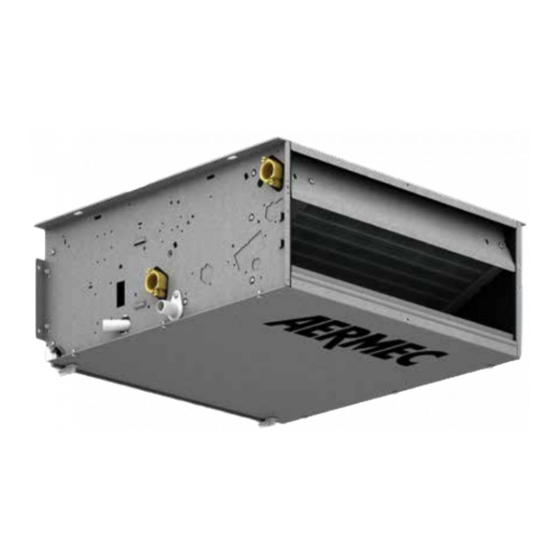
Page 9: Componenti Principali
COMPONENTI PRINCIPALI 1 Fiancata destra (struttura portante) 6 Sfiati / scarichi sulla batteria 10 Ventilatore centrifugo 2 Flangia di mandata dell'aria 7 Collegamenti idraulici 12 Scatola elettrica del motore elettrico 3 Batteria di scambio termico 8 Scarico condensa 13 Motore elettrico 4 Bacinella raccolta condensa / Pannello 9 Asole per il fissaggio 14 Pannello di chiusura frontale (inferiore) -
Page 10: Limiti Di Funzionamento
LIMITI DI FUNZIONAMENTO Massima temperatura ingresso acqua °C Massima temperatura ingresso acqua consigliata °C Massima pressione d’esercizio Minima portata d'acqua (Batteria principale) Massima portata d'acqua (Batteria principale) 3000 3000 3000 3000 3000 3000 3000 3000 Minima portata d'acqua (Batteria Solo Riscaldamento) Massima portata d'acqua (Batteria Solo Riscaldamento) 2000 1500... -
Page 11: Informazioni Per L'installazione
INFORMAZIONI PER L'INSTALLAZIONE ATTENZIONE: prima di effettuare dell'installatore il perfezionamento l’aria. qualsiasi intervento, assicurarsi che di tutte le operazioni a seconda delle I ventilconvettori VED sono dotati l’alimentazione elettrica sia disinserita. esigenze specifiche. di motori a 5 velocità, è possibile E’... -
Page 12: Collegamenti Idraulici
COLLEGAMENTI IDRAULICI - Effettuare i collegamenti idraulici. ATTENZIONE: Utilizzare sempre chiave e controchiave per fissare le tubazioni. La posizione, il tipo e il diametro degli attacchi idraulici sono riportati nei dati dimensionali. Si consiglia di isolare adeguatamente le tubazioni dell’acqua e/o di installare l’apposita bacinella ausiliaria di raccolta condensa, disponibile come accessorio, per evitare gocciolamenti... -
Page 13: Scarico Condensa
SCARICO CONDENSA La bacinella del ventilconvettore Assicurarsi che lo scarico non utilizzato dispone di 2 raccordi di scarico sia chiuso e non abbia perdite. condensa con diamentro esterno La rete di scarico della condensa deve Øe=16mm. essere opportunamente dimensionata Si raccomanda di utilizzare il raccordo e le tubazioni posizionate in modo di scarico condensa posto nel lato da mantenere lungo il percorso... - Page 14 Made with materials of superior quality in strict compliance with safety regulations, VED is easy to use and will have a long life. The range of VED fan coils are designed for integration in the VMF system. The VMF (Variable Multi Flow) system is able to intelligently manage a complete hydronic system, made up of chiller/heat pump, a boiler, a network of fan coils (multi-speed or continuous modulation of the speed) divided into zones (up to 64), circulation pumps (up to 12) and heat recovery units with air quality sensor (up to 3), optimising conditioning and...
-
Page 15: During Operation
IMPORTANT INFORMATION AND MAINTENANCE WARNING: the fan coil is connected DO NOT USE EXCESSIVELY HOT accumulation of substances present to power supply and hydraulic circuit. WATER in the air of the room (clean the filter Operations performed by people Clean the fan coil with a soft cloth more often, especially if the room is not without the required technical skills or sponge soaked in water not over... -
Page 16: System Example
DESCRIPTION OF THE UNIT PURPOSE OF THE VED FANCOILS The fan coil is a room air treatment terminal unit for both winter and summer operation. The VED fancoils are designed to fit any ducted type system. In particular, the possibility to be integrated into the VMF system allows the control of a single fancoil with accessories and the management of the VED introduced in complex fancoil networks and their accessories. -
Page 17: Main Components
MAIN COMPONENTS 1 Right side (load-bearing structure) 6 Vents / discharges on the coil 10 Centrifugal fan 2 Air delivery flanges 7 Hydraulic connections 12 Electric motor electrical box 3 Heat exchange coil 8 Condensate drain 13 Electric motor 4 Condensate collection tray / 9 Fixing slots 14 Front closure panel (lower) Front panel (upper) -
Page 18: Operational Limits
OPERATIONAL LIMITS Maximum water inlet temperature °C Maximum recommended water inlet temperature °C Maximum operating pressure Minimum water flow rate (Main coil) Maximum water flow rate (Main coil) 3000 3000 3000 3000 3000 3000 3000 3000 Minimum water flow rate (Heating Only Coil) Maximum water flow rate (Heating Only Coil) 2000 1500... -
Page 19: Installation Information
INSTALLATION INFORMATION WARNING: check that the power sup- The fan coil must be installed in such a mum water temperature sensor can be ply is disconnected before carrying out position that the air can be distributed installed in two locations: any procedures on the unit. -
Page 20: Hydraulic Connections
HYDRAULIC CONNECTIONS - Make the hydraulic connections. WARNING: Always use a wrench and counter-wrench to fix the pipes. Refer to the size data for the position, type and diameter of the hydraulic connections. You are advised to adequately insulate water lines and/or fit the auxiliary condensate drain tray (available as an accessory), to prevent dripping during the cooling function. -
Page 21: Condensate Discharge
CONDENSATE DISCHARGE The tray of the fan coil has 2 condensate The condensate drain network must be drainage connections with external properly scaled and the piping situated diameter Ø = 16mm. in such a way as to keep an adequate The condensate drain connection should slope along the route (min. - Page 22 Réalisé avec des matériaux de qualité supérieure, dans le plus grand respect des règles de sécurité, le modèle VED est facile à utiliser et il a été conçu pour durer longtemps. La série de ventilo-convecteurs VED est conçue pour être intégrée dans le système VMF. VMF (Variable Multi Flow) est le système en mesure de gérer de manière intelligente une installation hydronique complète, il est composé...
-
Page 23: Pendant Le Fonctionnement
INFORMATIONS IMPORTANTES ET ENTRETIEN ATTENTION : le ventilo-convecteur est utiliser des chiffons ou des éponges gréables dues à l'accumulation de branché au réseau électrique et au souples et mouillés avec de l’eau dont substances présentes dans l'air ambiant circuit hydraulique: l’intervention de la température maximale ne dépasse (notamment, si la pièce n'est pas aérée personnel dépourvu des compétences... -
Page 24: Exemples D'installation
DESCRIPTION DE L’UNITE OBJET DES VENTILO-CONVECTEURS VED Le ventilo-convecteur est une unité terminale servant au traitement de l’air d’un milieu tant en hiver qu’en été. Les ventilo-convecteurs VED sont conçus pour s'adapter à toutes les exigences des installations canalisées. En particulier, la possibilité d'être intégré dans le système VMF permet le contrôle du ventilo-convecteur individuel avec accessoires à la gestion de l'unité... -
Page 25: Composants Principaux
COMPOSANTS PRINCIPAUX 1 Flanc droit (structure portante) 6 Évents/conduits d'évacuation sur la batterie 10 Ventilateur centrifuge 2 Bride de soufflage de l'air 7 Raccordements hydrauliques 12 Armoire électrique du moteur électrique 3 Batterie d'échange thermique 8 Évacuation des condensats 13 Moteur électrique 4 Bac de récupération des condensats/ 9 Rainures pour la fixation 14 Panneau de fermeture frontal (inférieur) -
Page 26: Limites De Fonctionnement
LIMITES DE FONCTIONNEMENT Température maximale de l'eau à l'entrée °C Température maximale conseillée de l'eau à l'entrée °C Pression de service maximale bars Débit d'eau minimal (Batterie principale) Débit d'eau maximal (batterie principale) 3000 3000 3000 3000 3000 3000 3000 3000 Débit d'eau minimal (batterie chauffage seul) Débit d'eau maximal (Batterie chauffage seul) -
Page 27: Installation De L'unité
INFORMATIONS POUR L'INSTALLATION ATTENTION : avant d'effectuer une Nous laissons toutefois à l'installateur et L’unité VED est prévue pour les raccor- quelconque intervention, vérifier si à son expérience le soin de perfection- dements avec des canalisations d'air. l'alimentation électrique est débran- ner toutes les opérations en fonction Les ventilo-convecteurs VED sont équi- chée. -
Page 28: Raccordements Hydrauliques
RACCORDEMENTS HYDRAULIQUES - Effectuer les raccordements hydrau- liques. ATTENTION : Utiliser toujours une clé et une contre-clé pour fixer les tuyaux. La position, le type et le diamètre des raccordements hydrauliques sont repor- tés dans les données dimensionnelles. Il est conseillé d'isoler de manière appropriée les tuyaux de l'eau et/ou d'installer le bac auxiliaire de récu- pération des condensats prévu, dispo-... - Page 29 ÉVACUATION DES CONDENSATS Le bac du ventilo-convecteur dispose Le réseau d'évacuation des condensats de deux raccords d'évacuation des doit avoir les dimensions adéquates condensats dont Øe=16 mm. et les tuyaux doivent s'installer de Il est conseillé d'utiliser le raccord manière à garder tout au long du d'évacuation des condensats placé...
- Page 30 Das Modell "VED", das aus erstklassigen Materialien und unter strenger Beachtung der Sicherheitsbestimmungen hergestellt wurde, ist benutzerfreundlich und zeichnet sich durch eine lange Lebensdauer aus. Die VED-Baureihe der Gebläsekonvektoren wurde für den Einbau in das VMF-System konzipiert. VMF (Variable Multi Flow) ist ein intelligentes Steuerungssystem für eine komplette hydroni- sche Anlage und besteht aus einem Kaltwassersatz/Wärmepumpe, einem Heizkessel, einem Gebläsekonvektorennetz (mit mehrstufiger Drehzahl oder permanenter Drehzahlmodulation), das in (bis zu 64) Bereiche unterteilt ist, (bis zu 12) Umlaufpumpen und (bis zu 3) Wärme-...
- Page 31 WICHTIGE INFORMATIONEN UND WARTUNG ACHTUNG: Der Gebläsekonvektor KEIN ZU HEISSES WASSER VERWENDEN Ansammlung von in der Umgebungsluft ist mit dem Stromnetz und dem Benutzen Sie für die Reinigung des Geblä- vorhandenen Stoffen einen unangeneh- Wasserkreis verbunden. Somit kann ein sekonvektors einen weichen, höchstens men Geruch (besonders wenn keine Eingriff durch Personal, das nicht über 40 °C warmen und feuchten Lappen...
- Page 32 BESCHREIBUNG DER EINHEIT ZWECK DER VED-GEBLÄSEKONVEKTOREN Der Gebläsekonvektor ist eine Endeinheit für die Raumluftbehandlung sowohl für den Winter- als auch den Sommerbetrieb. Die VED- Gebläsekonvektoren sind darauf ausgerichtet, sich an jede Bedarfssituation in den Kanal-Klimaanlagen anzupassen. Insbesondere die Möglichkeit in das VMF-System integriert zu werden, erlaubt die Steuerung von einzelnen Gebläsekonvektoren mit Zubehörteilen bis hin zur Steuerung eines VED, der in die komplexen Netze der Gebläsekonvektoren und ihrer Zubehörteile eingefügt ist.
- Page 33 HAUPTKOMPONENTEN 1 Rechte Seitenwand (tragende Struktur) 5 Linke Seitenwand (tragende Struktur) 11 Filterhalter 2 Zuluftflansch 6 Entlüftungen / Ablässe am Wärmetauscher 10 Radialventilator 3 Wärmetauscher für den thermischen 7 Hydraulikanschlüsse 12 Schaltkasten vom E-Motor Austausch 8 Kondensatablass 13 Elektromotor 4 Kondensatauffangwanne / 9 Befestigungsösen 14 Frontabschlussplatte (unten) Frontabschlussplatte (oben)
- Page 34 GRENZWERTE FÜR DEN GERÄTEBETRIEB Maximale Wassereintrittstemperatur °C Empfohlene maximale Wassereintrittstemperatur °C Maximaler Betriebsdruck Mindestwasserdurchsatz (Hauptwärmetauscher) Maximaler Wasserdurchsatz (Hauptwärmetauscher) 3000 3000 3000 3000 3000 3000 3000 3000 Mindestwasserdurchsatz (Wärmetauscher für reinen Heizbetrieb) Maximaler Wasserdurchsatz (Wärmetauscher für reinen 2000 1500 2000 1500 Heizbetrieb) Raumtemperaturgrenzen (Ta) °C...
-
Page 35: Informationen Zur Installation
INFORMATIONEN ZUR INSTALLATION ACHTUNG: Bevor Sie irgend einen Ein- Die Wasserleitungen, der Kondensa- Geschwindigkeitsstufen verfügen, davon griff vornehmen, sicherstellen, dass tablauf und der elektrische Schaltkreis können 3 als Betriebsgeschwindig- dem Gerät kein Strom zugeführt wird. müssen bereits vorbereitet sein. keiten ausgewählt werden, indem die Der Gebläsekonvektor muss so installiert Anschlüsse im Schaltkasten des Motors ACHTUNG: Rüsten Sie sich vor jedem... - Page 36 WASSERANSCHLÜSSE - Verlegen Sie die Wasseranschlüsse. ACHTUNG: Zum Befestigen der Rohrlei- tungen immer einen Schraubenschlüs- sel und Konterschlüssel verwenden. Position, Typ und Durchmesser der Wasseranschlüsse finden Sie bei den Abmessungsangaben. Es empfiehlt sich die Wasserleitungen gut zu isolieren und / oder die als Zubehör erhältliche zusätzliche Kon- densatauffangwanne zu installieren, um zu vermeiden, dass während des...
- Page 37 KONDENSATABLASS Die Auffangwanne des Gebläsekon- Stellen Sie sicher, dass der ungenutzte vektors verfügt über 2 Kondensatab- Ablass verschlossen ist und keine Lecks lassanschlüsse mit Außendurchmesser aufweist. Øe=16mm. Der Kondenswasserabfluss ist entspre- Es wird empfohlen den Kondensatablas- chend zu dimensionieren und die sanschluss zu verwenden, der sich auf Leitungen müssen so angeordnet der Seite der Wasseranschlüsse befindet.
- Page 38 Fabricado con materiales de calidad superior y en total conformidad con las normativas de seguridad, VED es fácil de usar y podrá disfrutarlo durante mucho tiempo. La serie de fan coils VED está diseñada para ser integrada en el sistema VMF. VMF (Variable Multi Flow) es el sistema en condiciones de gestionar de modo inteligente una instalación hidrónica completa, compuesta por un refrigerador/bomba de calor, una caldera, una red de fan coils (multivelocidad o modulación continua de la velocidad) subdivididos...
-
Page 39: Durante El Funcionamiento
INFORMACIÓN IMPORTANTE Y MANTENIMIENTO ATENCIÓN: El fan coil está conectado a use productos químicos ni disolventes advertirse ruidos y crujidos dentro del la red eléctrica y al circuito hidráulico: para limpiar ninguno de los compo- aparato debidos a las diferentes dilata- cualquier intervención por parte de nentes del fan coil. -
Page 40: Descripción De La Unidad
DESCRIPCIÓN DE LA UNIDAD OBJETIVO DE LOS FAN COILS VED El fan coil es un terminal para el tratamiento del aire de un ambiente tanto en invierno como en verano. Los fan coils VED están diseñados para adaptarse a cualquier necesidad en las instalaciones de tipo canalizado. Especialmente la posibilidad de integrarlos al sistema VMF permite controlar desde un único fan coil con accesorios hasta el VED incorporado a redes complejas de fan coils y sus accesorios. -
Page 41: Componentes Principales
COMPONENTES PRINCIPALES 1 Lateral derecho (estructura de sustentación) 5 Lateral izquierdo (estructura de sustentación) 11 Soporte para filtro 2 Brida de ventilación del aire 6 Respiraderos / descargas en la batería 10 Ventilador centrífugo 3 Batería de intercambio térmico 7 Conexiones hidráulicas 12 Caja eléctrica del motor eléctrico 4 Cubeta de recolección de la 8 Descarga de condensación... -
Page 42: Límites De Funcionamiento
LÍMITES DE FUNCIONAMIENTO Temperatura máxima de entrada de agua °C Máxima temperatura de entrada de agua recomendada °C Presión máxima de funcionamiento Mínimo caudal de agua (Batería principal) Máximo caudal de agua (Batería principal) 3000 3000 3000 3000 3000 3000 3000 3000 Mínimo caudal de agua (Batería sólo calor) -
Page 43: Información Para La Instalación
INFORMACIÓN PARA LA INSTALACIÓN ATENCIÓN: antes de realizar cualquier Es necesario prever la instalación de las motores de 5 velocidades. Se pueden intervención, controlar que esté desco- tuberías del agua, de la descarga del elegir 3 modos de trabajo modifican- nectada la alimentación eléctrica. -
Page 44: Conexiones Eléctricas
CONEXIONES HIDRÁULICAS - Hacer las conexiones hidráulicas. ATENCIÓN: Utilizar siempre llave y con- trallave para fijar las tuberías. La posición, el tipo y el diámetro de las conexiones hidráulicas se indican en los datos de las dimensiones. Se recomienda aislar adecuadamente las tuberías del agua y/o instalar la corres- pondiente cubeta auxiliar de recolección del agua de condensación, disponible... - Page 45 DESCARGA DE CONDENSACIÓN La cubeta del fan coil dispone de 2 raco- Controlar que la descarga que no se uti- res de descarga de condensación con liza esté cerrada y no pierda. un diámetro exterior de Øe=16mm. La red de descarga del agua de condensa- Se recomienda utilizar el racor de des- ción debe tener la medida correcta y las carga de condensación situado en el...
- Page 46 DIMENSIONI [mm] VED 430 - 440 - 530 -540 - 432 - 441 - 532 - 541 1158 1133 1053 Ø16 1104 1109 Attacchi idraulici batteria principale (femmina) Main coil water connections (female) Raccords hydrauliques de la batterie principale (femelle) Ø...
- Page 47 DIMENSIONI [mm] VED 630 - 640 - 730 -740 - 632 - 641 - 732 - 741 1558 1533 1453 Ø16 1504 1509 Attacchi idraulici batteria principale (femmina) Main coil water connections (female) Raccords hydrauliques de la batterie principale (femelle) Ø...
- Page 48 SCHEMI ELETTRICI • WIRING DIAGRAMS • SCHEMAS ELECTRIQUES • SCHALTPLÄNE • ESQUEMAS ELÉCTRICOS LEGENDA • READING KEY • LEGENDE • LEGENDE • LEYENDA = Fusibile • Fuse • Fusible • Sicherung • Fusible = Interruttore generale • Master switch • Interrupteur général • Hauptschalter • Interruptor general = Morsettiera •...
- Page 49 SCHEMI ELETTRICI • WIRING DIAGRAMS • SCHEMAS ELECTRIQUES • SCHALTPLÄNE • ESQUEMAS ELÉCTRICOS VMF-E0 VMF-E4 (---------------------------------------30 m MAX-----------------------------------) VMF-SIT3 ÷ E0/1 Slave 1 E0/1 Master Only master VMF-E4 CN27 CN17 VMF-E0 CN7-B CN7-A VMF-SIT3 VMF-SIT3 230V 50Hz 2 3 4 5 Gli schemi elettrici sono soggetti ad un continuo aggiornamento, è...
- Page 50 SCHEMI ELETTRICI • WIRING DIAGRAMS • SCHEMAS ELECTRIQUES • SCHALTPLÄNE • ESQUEMAS ELÉCTRICOS VMF-E1 (---------------------------------------30 m MAX-----------------------------------) VMF-E4 ÷ E0/1 Slave 1 E0/1 Master VMF-SIT3 MODBUS 12Vdc (E5) 0Vdc Only master VMF-E4 CN27 CN17 CN16 SLOT EXPANSION VMF-E1 CN23 CN22 CN25 CN26 CN14...
- Page 51 SCHEMI ELETTRICI • WIRING DIAGRAMS • SCHEMAS ELECTRIQUES • ELEKTRISCHE SCHALTPLÄNE • ESQUEMAS ELECTRICOS VMF-E1 (master + slave) VMF-E5 VMF-E4 Los esquemas eléctricos están sujetos a modificaciones continuas, por lo tanto es obligatorio tomar la referencia de los que se encuentran a bordo de la máquina. A l l w i r i n g d i a g r a m s...
- Page 52 SCHEMI ELETTRICI • WIRING DIAGRAMS • SCHEMAS ELECTRIQUES • ELEKTRISCHE SCHALTPLÄNE • ESQUEMAS ELECTRICOS TTL Seriale locale TTL Local serial TTL Liaison série locale TTL Lokale serielle Schnittstelle TTL Serial Local Los esquemas eléctricos están sujetos a modificaciones continuas, por lo tanto es obligatorio tomar la referencia de los que se encuentran a bordo de la máquina. A l l w i r i n g d i a g r a m s...
- Page 53 SCHEMI ELETTRICI • WIRING DIAGRAMS • SCHEMAS ELECTRIQUES • ELEKTRISCHE SCHALTPLÄNE • ESQUEMAS ELECTRICOS VMF-E1 / VMF-E5 (RS485 Seriale supervisione) VMF-E1 / VMF-E5 (RS485 Supervision serial) VMF-E1 / VMF-E5 (RS485 Liaison série de supervision) VMF-E1 / VMF-E5 (RS485 Serielle Überwachungsschnittstelle) VMF-E1 / VMF-E5 (RS485 Serial supervisión) Los esquemas eléctricos están sujetos a modificaciones continuas, por lo tanto es obligatorio tomar la referencia de los que se encuentran a bordo de la máquina.
- Page 54 SCHEMI ELETTRICI • WIRING DIAGRAMS • SCHEMAS ELECTRIQUES • ELEKTRISCHE SCHALTPLÄNE • ESQUEMAS ELECTRICOS RS485 Seriale supervisione (Alimentazione esterna VMF-E5) RS485 Supervision serial (VMF-E5 external power supply) RS485 Liaison série de supervision (Alimentation externe VMF-E5) RS485 Serielle Überwachungsschnittstelle (Externe Stromversorgung VMF-E5) RS485 Serial supervisión (Alimentación externa VMF-E5) 22AWG-3 22AWG-3...
- Page 55 SCHEMI ELETTRICI • WIRING DIAGRAMS • SCHEMAS ELECTRIQUES • ELEKTRISCHE SCHALTPLÄNE • ESQUEMAS ELECTRICOS RS485 Seriale supervisione + E5 alimentazione VMF-E5 RS485 Supervision serial + E5 VMF-E5 power supply RS485 Liaison série de supervision + E5 Alimentation VMF-E5 RS485 Serielle Überwachungsschnittstelle + E5 Versorgung VMF-E5 RS485 Serial supervisión + E5 Alimentación VMF-E5 22AWG-3 22AWG-5...
- Page 56 SCHEMI ELETTRICI • WIRING DIAGRAMS • SCHEMAS ELECTRIQUES • ELEKTRISCHE SCHALTPLÄNE • ESQUEMAS ELECTRICOS Seriale supervisione RS485 (VMF_E1 - MODU_485A) Supervision serial RS485 (VMF_E1 - MODU_485A) Liaison série de supervision RS485 (VMF_E1 - MODU_485A) Serielle Überwachungsschnittstelle E1 - MODU_485A Serial supervisión RS485 (VMF_E1 - MODU_485A) 22AWG-3 22AWG-3 MODU-485A...
- Page 57 SCHEMI ELETTRICI • WIRING DIAGRAMS • SCHEMAS ELECTRIQUES • SCHALTPLÄNE • ESQUEMAS ELÉCTRICOS SIT3 SIT3 Control Panel SIT3 230V 50Hz PE 2 3 4 5 Gli schemi elettrici sono soggetti ad un continuo aggiornamento, è obbligatorio quindi fare riferimento a quelli a bordo macchina. A l l w i r i n g d i a g r a m s...
- Page 58 SCHEMI ELETTRICI • WIRING DIAGRAMS • SCHEMAS ELECTRIQUES • SCHALTPLÄNE • ESQUEMAS ELÉCTRICOS PXAE SIT3 V1 V2 V3 INPUT OUTPUT SIT3 230V 50Hz PE 2 3 4 5 Gli schemi elettrici sono soggetti ad un continuo aggiornamento, è obbligatorio quindi fare riferimento a quelli a bordo macchina. A l l w i r i n g d i a g r a m s...
- Page 59 SCHEMI ELETTRICI • WIRING DIAGRAMS • SCHEMAS ELECTRIQUES • SCHALTPLÄNE • ESQUEMAS ELÉCTRICOS PXAE SIT3 SIT5 Gli schemi elettrici sono soggetti ad un continuo aggiornamento, è obbligatorio quindi fare riferimento a quelli a bordo macchina. A l l w i r i n g d i a g r a m s a r e c o n s t a n t l y...
- Page 60 SCHEMI ELETTRICI • WIRING DIAGRAMS • SCHEMAS ELECTRIQUES • SCHALTPLÄNE • ESQUEMAS ELÉCTRICOS VED 4 - 5 WMT10 WMT10 230V 50Hz PE VED 430 VED 440 VED 530 VED 540 VED 432 VED 441 VED 532 2 3 4 5 VED 541 Gli schemi elettrici sono soggetti ad un continuo aggiornamento, è...
- Page 61 SCHEMI ELETTRICI • WIRING DIAGRAMS • SCHEMAS ELECTRIQUES • SCHALTPLÄNE • ESQUEMAS ELÉCTRICOS VED 6 - 7 WMT10 SIT3 WMT10 V1 V2 V3 INPUT OUTPUT SIT3 230V 50Hz PE VED 630 VED 640 VED 730 VED 740 VED 632 VED 641 VED 732 2 3 4 5 VED 741...
- Page 62 SCHEMI ELETTRICI • WIRING DIAGRAMS • SCHEMAS ELECTRIQUES • SCHALTPLÄNE • ESQUEMAS ELÉCTRICOS VED 4 - 5 - 6 - 7 WMT05 WMT05 3 5 4 1 2 230V 50Hz PE VED 430 VED 630 VED 440 VED 640 VED 530 VED 730 VED 540 VED 740...
- Page 63 SCHEMI ELETTRICI • WIRING DIAGRAMS • SCHEMAS ELECTRIQUES • SCHALTPLÄNE • ESQUEMAS ELÉCTRICOS VED 4 - 5 - 6 - 7 WMT06 WMT06 3 5 4 1 2 230V 50Hz PE VED 430 VED 630 VED 440 VED 640 VED 530 VED 730 VED 540 VED 740...
- Page 64 PROBLEMA • PROBLEM PROBABILE CAUSA • PROBABLE CAUSE SOLUZIONE • REMEDY PROBLEME • PROBLEM CAUSE PROBABLE • MÖGLICHE URSACHE SOLUTION • ABHILFE PROBLEMA CAUSA PROBABLE SOLUCIÓN Poca aria in uscita. Errata impostazione della velocità sul pannello comandi. Scegliere la velocità corretta sul pannello comandi. Feeble air discharge.
-
Page 68: Garanzia Di 3 Anni
AERMEC S.p.A. si riserva la facoltà di apportare in qualsiasi momento tutte le modifiche ritenute necessarie per il miglioramento del prodotto. Les données mentionnées dans ce manuel ne constituent aucun engagement de notre part. Aermec S.p.A. se réserve le droit de modifier à tous moments les données considérées nécessaires à...
Need help?
Do you have a question about the VED Series and is the answer not in the manual?
Questions and answers