Table of Contents
Advertisement
Available languages
Available languages
VENTILCONVETTORE PER INSTALLAZIONE CANALIZZATA, ORIZZONTALE E VERTICALE
HORIZONTALLY AND VERTICALLY DUCTED INSTALLATION FAN COIL UNITS
VENTILO-CONVECTEUR POUR INSTALLATION HORIZONTALE ET VERTICALE AVEC CANAUX
GEBLÄSEKONVEKTOR FÜR DIE HORIZONTALE UND VERTIKALE INSTALLATION MIT KANÄLEN
VENTILOCONVECTOR PARA INSTALACIÓN HORIZONTAL Y VERTICAL CON CANALES
MANUALE D'USO E INSTALLAZIONE
USER AND INSTALLATION MANUAL
MANUEL D'UTILISATION ET D'INSTALLATION
BEDIENUNGS- UND INSTALLATIONSANLEITUNG
MANUAL DE USO E INSTALACIÓN
VES 030 I
VES 040 I
IT
GB
pag.5
pag.21
VES_I
VES 130 I
VES 230 I
VES 140 I
VES 240 I
VES 330 I
VES 340 I
Cod. 5799550_01
Advertisement
Table of Contents

Related Manuals for AERMEC VES I Series


Summary of Contents for AERMEC VES I Series
- Page 1 MANUALE D’USO E INSTALLAZIONE USER AND INSTALLATION MANUAL MANUEL D’UTILISATION ET D’INSTALLATION BEDIENUNGS- UND INSTALLATIONSANLEITUNG MANUAL DE USO E INSTALACIÓN VENTILCONVETTORE PER INSTALLAZIONE CANALIZZATA, ORIZZONTALE E VERTICALE HORIZONTALLY AND VERTICALLY DUCTED INSTALLATION FAN COIL UNITS VENTILO-CONVECTEUR POUR INSTALLATION HORIZONTALE ET VERTICALE AVEC CANAUX GEBLÄSEKONVEKTOR FÜR DIE HORIZONTALE UND VERTIKALE INSTALLATION MIT KANÄLEN VENTILOCONVECTOR PARA INSTALACIÓN HORIZONTAL Y VERTICAL CON CANALES VES_I...
- Page 2 Gentile cliente, La ringraziamo per aver preferito nell’acquisto un prodotto AERMEC. Esso è frutto di pluriennali esperienze e di particolari studi di progettazione, ed è stato costruito con materiali di primissima scelta e con tecnologie avanzatissime. La marcatura CE, inoltre, garantisce che gli apparecchi rispondano ai requisiti della Direttiva Macchi- ne Europea in materia di sicurezza.
-
Page 3: Table Of Contents
Collegamento dei canali dell’aria all’unità .......... 15 17.8. Duct connections to the unit .............. 31 8.9. Rotazione della batteria ..............16 17.9. Rotation of the coil ................32 Manutenzione e precauzioni per l’uso ........... 17 18. Maintenance and precautions for use ..........33 9.1. Problemi e soluzioni ................18 18.1. Problems and solutions ..............34 Aermec 17.12 Cod. 5799550_01... -
Page 4: Avvertenze Generali
AERMEC non si assume nessuna LIMITI DI FUNZIONAMENTO responsabilità per danni insorti a causa Le unità VES_I AERMEC sono costruite dell’unità: della mancata osservanza di queste secondo gli standard tecnici e le regole istruzioni. -
Page 5: Campo Di Funzionamento
Per evitare fenomeni di condensazione latore spento e passaggio di acqua fredda sulla struttura esterna dell’apparecchio in batteria, è possibile la formazione di Temperatura a bulbo secco dell’aria ambiente MINIMA TEMPERATURA MEDIA ACQUA [°C] Temperatura a bulbo umido dell’aria ambiente Aermec 17.12 Cod. 5799550_01... -
Page 6: Informazioni
Nota: • l’integrità dell’imballo; Per ogni futuro riferimento e per ogni • l’integrità dell’unità e pannel- comunicazione con AERMEC S.p.A. è ne- latura; cessario indicare il numero di matricola. • la presenza di tutti i compo- nenti. 4.1. -
Page 7: Descrizione Dell'unità
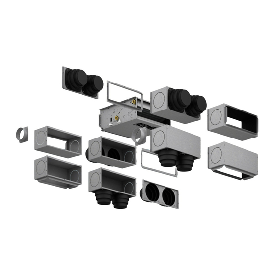
• Accessori valvole a 3 vie 4 attacchi. • Necessita di dispositivo di controllo • Accessori valvole a 2 vie per gli impianti a esterno (accessorio). portata d'acqua variabile. Installazione verticale Installazione orizzontale Aermec 17.12 Cod. 5799550_01... -
Page 8: Componenti Principali
Aermec mette a disposizione i dispositivi di Non risente di disturbi elettromagnetici. - Velocità minima garantita 90 rpm (per controllo come accessori. Il fatto che sia senza spazzole permette ragioni termodinamiche tale limite è... -
Page 9: Esempi Di Impianto
Batteria (Riscaldamento / Raffrescamento) Valvola (Riscaldamento) Batteria (Riscaldamento) Impianto 2 tubi con sonda acqua Impianto 2 tubi senza sonda acqua VC/F VC/F VC/F VC/F Impianto 4 tubi con sonda acqua Impianto 4 tubi senza sonda acqua VC/F VC/F VC/F VC/F VC/F Aermec 17.12 Cod. 5799550_01... -
Page 10: Installazione
I ventilconvettori che funzio- - Per installazione sospesa al soffitto neranno solamente in riscaldamento non usare quattro aste filettate da M8 per Aermec 17.12 Cod. 5799550_01... -
Page 11: Collegamenti Idraulici
Le valvole di sfiato sono posizionate nella parte alta della batteria in prossimità dei raccordi idraulici. Valvole di sfiato Attenzione: per scaricare l'unità utilizzare e scarico acqua dalla batteria le valvole di scarico posizionate nella parte più bassa della batteria in prossimi- tà dei raccordi idraulici. Aermec 17.12 Cod. 5799550_01... -
Page 12: Collegamenti Elettrici
2. La sezione del filo di neutro deve essere Nell’abbinamento dei dispositivi di con- dimensionata considerando una corrente trollo deve essere rispettato lo schema di esercizio pari al 170% del valore assor- elettrico relativo e le indicazioni riportate Aermec 17.12 Cod. 5799550_01... -
Page 13: Codifica Allarmi
Per il reset allarmi: Led Alarm permanentemente Set 0V ON INPUT STOP Motore Spento acceso ( t o g l i e r e t e n s i o n e e riaccendere) Aermec 17.12 Cod. 5799550_01... -
Page 14: Dispositivi Di Controllo (Non Incluso)
DISPOSITIVO DI CONTROLLO 0V - 10V Utilizzare un dispositivo di controllo con termostato e controllo delle velocità di ventilazione con uscite 0-10V e caratteristi- che compatibili con l’unità. Per l’installazione consultare i manuali dell’unità e dell’accessorio. Aermec 17.12 Cod. 5799550_01... -
Page 15: Collegamento Scarico Condensa
Per identificare la posizione dei canali con- Durante il funzionamento lasciare sempre sultare il disegno. il filtro montato sul ventilconvettore altri- Aermec 17.12 Cod. 5799550_01... -
Page 16: Rotazione Della Batteria
- Rimontare il pannello di chiusura ante- – Rimontare il coperchio di chiusura della riore. batteria, fissandolo con le viti. 180° Aermec 17.12 Cod. 5799550_01... -
Page 17: Manutenzione E Precauzioni Per L'uso
Il cavo andrà a sporcare le superfici della batte- danneggiato può provocare corti circuiti e ria. danni alle persone. È NORMALE Non infilare oggetti sull’uscita dell’aria Aermec 17.12 Cod. 5799550_01... -
Page 18: Problemi E Soluzioni
Sono state raggiunte le condizioni limite di temperatura e umidi- Innalzare la temperatura dell’acqua oltre i limiti minimi descritti struttura esterna dell’apparecchio. tà descritte in “MINIMA TEMPERATURA MEDIA DELL’ACQUA”. in “MINIMA TEMPERATURA MEDIA DELL’ACQUA”. Per anomalie non contemplate, interpellare tempestivamente il Servizio Assistenza. Aermec 17.12 Cod. 5799550_01... - Page 19 Aermec 17.12 Cod. 5799550_01...
-
Page 20: General Warnings
− The unit must be installed by a com- petent and qualified technician, and OPERATING LIMITS of the unit: in accordance with the legislation ap- The AERMEC VES_I units are manufac- plicable in the country of installation. tured in accordance with recognised Maximum entering water temper-... -
Page 21: Operating Range
Ambient dry bulb temperature MINIMUM AVERAGE WATER TEMPERATURE [°C] Ambient wet bulb temperature Aermec 17.12 Cod. 5799550_01... -
Page 22: Information
Note: For any future reference or communica- 13.4. INSTALLATION tion with AERMEC S.p.A. it is necessary to state the unit serieal number. It is recommended to carefully follow the instructions provide in the follow- 13.1. MOVEMENT ing paragraphs for the installation. -
Page 23: Unit Description
• Prepared for installation into the VMF • Class 1 internal insulation. system. • Full compliance with safety standards. • Wide range of controls and accessories. • Ease of installation and maintenance. Vertical installation Horizontal installation Aermec 17.12 Cod. 5799550_01... -
Page 24: Main Components
- Higher energy efficiency - standard and oversized main coil for hot used by the AERMEC VES fan coil units - Higher reliability and lifetime water heating only provide the most sophisticated mechani-... -
Page 25: System Examples
Coil (Heating/Cooling) Valve (Heating) Coil (Heating) 2 pipe system with water sensor 2 pipe system without water sensor VC/F VC/F VC/F VC/F 4 pipe system with water sensor 4 pipe system without water sensor VC/F VC/F VC/F VC/F VC/F Aermec 17.12 Cod. 5799550_01... -
Page 26: Installation
- Start the fan coil unit and check the sion plugs (not provided) and ensure the recommended that the water piping is operation of the components and all the unit is installed level. properly insulated. functions. - For ceiling hung installations use four M8 - Carry out the condensate discharge Aermec 17.12 Cod. 5799550_01... -
Page 27: Hydraulic Connections
Warning: To drain the unit use the drain Coil vent and drain valves valves located on the lower part of the coil close to the hydraulic connections. Aermec 17.12 Cod. 5799550_01... -
Page 28: Electrical Connections
If present, connect the valve and the sen- CHARACTERISTICS OF THE CONNECTING sor to the terminal block as shown in the Aermec 17.12 Cod. 5799550_01... -
Page 29: Alarm Codes
- the system switches off. Over current Overload Capacity limitation LED ALARM flashes Reduced speed 0.5sec ON / 0.5sec OFF Safety control Temperature limitation To reset alarms: STOP LED Alarm permanently on Motor off Set 0V ON INPUT (remove and re-apply power) Aermec 17.12 Cod. 5799550_01... -
Page 30: Control Device (Not Included)
Use a control device with thermostat and and the accessory manual. speed control of the fan with a 0-10V out- put and with characteristics compatible with the fan coil unit. For the installation consult the unit manual Aermec 17.12 Cod. 5799550_01... -
Page 31: Condensate Discharge Connection
Connect the ducting to the connections us- dust in the air will dirty the coil. tions. ing straps. To identify the duct connections refer to Ensure that the filter is always mounted on the drawings. the unit during operation, otherwise the Aermec 17.12 Cod. 5799550_01... -
Page 32: Rotation Of The Coil
- Refit the frontal enclosure panel. side must be completely filled and closed with insulating material. – Refit the coil sealing cover and fix with the screws. – Close with insulating material the holes 180° Aermec 17.12 Cod. 5799550_01... -
Page 33: Maintenance And Precautions For Use
During cooling, water vapour may be pre- Do not put anything at all in the air outlet sent in the air discharge. slots. During heating it might be possible to This could cause injury to people and dam- Aermec 17.12 Cod. 5799550_01... -
Page 34: Problems And Solutions
Increase the water temperature beyond the minimum limits indi- Condensation on the unit cabinet. “MINIMUM AVERAGE WATER TEMPERATURE” have been cated in “MINIMUM AVERAGE WATER TEMPERATURE”. reached. For anomalies don’t hesitate, contact the aftersales service immediately. Aermec 17.12 Cod. 5799550_01... - Page 35 1/2"G* 1/2"G* 1/2"G* 1/2"G* 1/2"G* 1/2"G* 1/2"G* 1/2"G* (femelle) Wasseranschlüsse für Wärmetauscher für reinen Heizbetrieb (Innengewinde) Conexiones hidráulicas batería sólo calor (hembra) Attacchi scarico condensa (diametro esterno) Condensate discharge connections (external diameter) Raccords d'évacuation des condensats (diamètre exté- 20,5 20,5 20,5 20,5 20,5 20,5 20,5 20,5 rieur) Anschlüsse für Kondensatablass (Außendurchmesser) Conexiones de descarga de condensación (diámetro exterior) * = Accessorio • Accessory • Accessoire • Zubehörteil • Accesorio Aermec 17.12 Cod. 5799550_01...
- Page 36 = jaune-vert = Gelb/Grün = Amarillo-Verde = Marrone = Brown = marron = Braun = Marrón = Nero = Black = noir = Schwarz = Negro = Rosso = Red = rouge = Rot = Rojo Aermec 17.12 Cod. 5799550_01...
- Page 37 VES 030 I VES 040 I VES 130 I VES 140 I VES 230 I VES 240 I VES 330 I VES 340 I FC--U 1 2 3 4 Dis.5384020_01 Aermec 17.12 Cod. 5799550_01...
- Page 38 Die Schaltpläne werden ständig aktualisiert, deswegen muss man sich stets auf das mit dem Gerät gelieferte Schaltschema beziehen. El cableado de las máquinas es sometido a actualizaciones constantes. Por favor, para cada unidad remitirse a los esquemas suministrados con la misma. Aermec 17.12 Cod. 5799550_01...
- Page 39 DATI IN ACCORDO CON IL REGOLAMENTO EU 2016/2281 • DATA IN ACCORDANCE WITH EU REGULATION 2016/2281 • DONNÉES SELON LA RÉGLE- MENTATION DE L’UE 2016/2281 • DATEN GEMÄSS EU 2016/2281-VERORDNUNG • DATOS SEGÚN LA REGULACIÓN DE LA UE 2016/2281 VESI 030-340 Taglie - size - Tailles - Größen - Tamaños (1) Impostazione velocità...
- Page 40 AERMEC S.p.A. si riserva la facoltà di apportare in qualsiasi momento tutte le modifiche ritenute necessarie per il miglioramento del prodotto. Les données mentionnées dans ce manuel ne constituent aucun engagement de notre part. Aermec S.p.A. se réserve le droit de modifier à tous moments les données considérées nécessaires à...
Need help?
Do you have a question about the VES I Series and is the answer not in the manual?
Questions and answers