Table of Contents
Advertisement
Quick Links
Thank you for purchasing our product. Before installing/operating the product, please read the instructions carefully and retain them
for future reference.
Attention!
● For installation, please follow the steps described. Any damage caused by wrong installation shall be imputed to the users.
● To avoid a short circuit from occuring do not pull or modify the wires during installation.
● Do not disassemble or change any parts. Opening and dissassembling this unit will void any warranty.
● Maintenance and repairs should be executed by our professionals only.
Symbol description:
NOTE
Some procedures must be followed to avoid damages to the instrument.
WARNING!
Certain procedures must be followed to avoid damages to yourself, to the vehicle or others.
1-1
Accessories
1
Meter X1
5
RPM wire set (Type B) X1
M5 x 5L mm Hexagon
9
screw x 2
13
Rubber x 1
17
M5 washer x 2
1-2
Optional accessories
1
Bolt Magnet
NOTE
The optional active speed sensor can read up to 20 pulsations and not require the installation of any magnets to pick up the speed.
Note that the passive speed sensor supplied with this instrument can read up to 6 pulsations.
NOTE
Some of the optional accessories listed might not be sold in your country. Contact your local distributor to get more details.
2
Passive speed sensor X1
6
Mid-way connector X 11
10
2.5 mm allen key x 1
14
M6 x 18L mm screw x 1
18
M6 washer x 1
2
Active speed sensor
3
D6 x 5L mm magnet x 6
7
M8/ S type speed
sensor bracket x 1
11
V type Meter bracket x 1
set
15
M5 x P0.8 mm nut x 2
19
Aluminum bushing x 1
3
L type speed sensor
bracket
Flash
Light on
Hold the
Hold the
Button
Button
1 second
3 seconds
4
RPM wire set (Type A) X1
8
M10/ S type speed
sensor bracket x 1
12
Handle bar clamp x 1
16
M6 x P1.0 mm nut x 1
Advertisement
Table of Contents

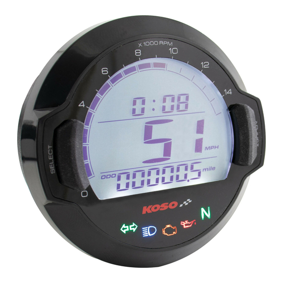
Summary of Contents for Koso BB642W20
- Page 1 Thank you for purchasing our product. Before installing/operating the product, please read the instructions carefully and retain them for future reference. Attention! ● For installation, please follow the steps described. Any damage caused by wrong installation shall be imputed to the users. ●...
- Page 2 Wiring instructions Red (+12V) (Connect to the battery DC 12V ) Purple / EOBD light (-) Orange / L turn signal (+12V) Blue / R turn signal (+12V) Brown / “+” Wire connect Yellow / High beam light (+12V) key on DC 12V main Gray / Oil light (-) power switch White / Neutral light (-)
- Page 3 “S” type speed sensor bracket Put the magnet into the Install the S type sensor Adjust the sensor bracket Install the speed sensor In order to get a good speed brake disc screw hole. bracket. position to make sure the on the bracket.
- Page 4 Main function switch (adjust button) Main function switch (select button) ●In the clock screen, press the Select Button ●In main screen (ODO). Press the Adjust once to switch to the volt screen. button once to enter the Trip A screen. NOTE If you don’t install the volt wiring, the volt ●press and hold the Adjust button for 3...
- Page 5 Entering setting screen ●In main screen, press and hold the Select & P.S. Adjust button for 3 seconds to enter the setting screen. ● You can define the valve as the starting point and the terminal point to measure the wheel circumference with a measuring tape.
- Page 6 THE CLOCK SETTING ●Press the Adjust button to change the setting value. ●Ex.: To set the clock at 0:05. ●Press the Select button and release it until it move to the digit you want to set. Now the setting digit value is flashing! NOTE This is a 24H clock.


Need help?
Do you have a question about the BB642W20 and is the answer not in the manual?
Questions and answers