Table of Contents
Advertisement
Quick Links
INSTALLATION
●
Thank you for purchasing the our product. Before installing, please read the instruction carefully and keep it for future reference.
Notice
●
Please, follow the step-by-step instructions for proper installation. Any damages caused by faulty installation shall be imputed to the users.
●
To avoid a short circuit, do not pull the wires when installing the unit. Do not break or modify the wires either.
●
Do not disassemble or change any parts.
●
Maintenance and repairs should be executed by our professionals only.
◎Mark Meaning:
NOTE
Yo
u could get the installation details from the information behind the mark.
Some processes must be followed to avoid the affection caused by wrong installation.
WARNING!
Some processes must be followed to avoid damages to yourself or the public.
CAUTION!
Some processes must be followed to avoid the damage to the vehicle.
1-1
Accessories
1
2
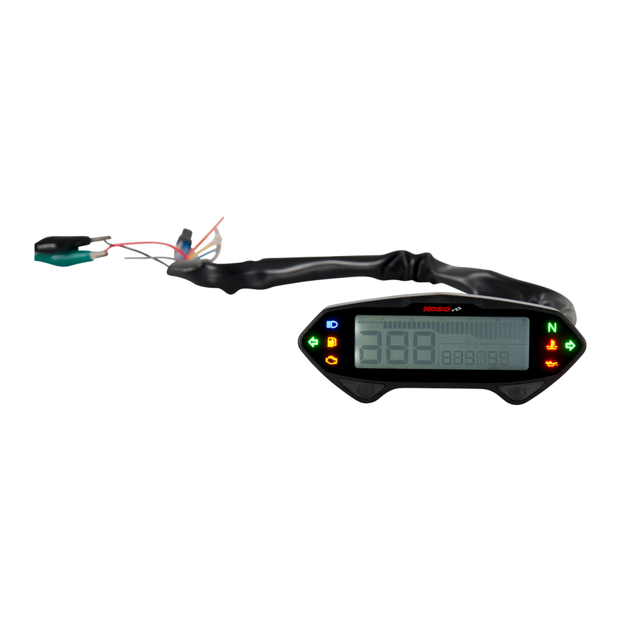
Meter X 1
Main wiring harness X 1
6
5
M8 / S type speed
Active speed sensor X 1
sensor bracket X 1
9
10
4 mm Allen key X 1
3 mm Allen key X 1
13
14
M4 X 10L screw X 2
M4 washer X 2
NOTE
Contact your local distributor, if the items received in the box are not the same as the items listed above.
1-2
Accessories
1
Digital speed signal
2
Digital speed signal
sensor
sensor
JIS TYPE A
RUNNER
5
Meter bracket
Some of the optional accessories may not be available in your area. Contact your local distributor to obtain more information.
NOTE
FLASH
LIGHT ON
PRESS THE
PRESS THE
BUTTON
BUTTON 3
ONCE
SECONDS
3
4
RPM wire (TYPE A) X 1
RPM wire (TYPE B) X 1
7
M10 / S type speed
8
M5 X 5L mm Hexagon
sensor bracket X 1
screw X 2
11
12
2 mm Allen key X 1
M5 X 12L screw X 2
15
Meter bracket X 1
3
4
L TYPE speed sensor
Digital speed signal
backet
sensor
SR
X-FIGHT
BOOSTER
2-1
Wiring installation instructions
Brown / Red - RPM wire please
connect it to the suitable position
according to the models
Main power switch wire reference:
Power
Key on
Ground
YAMAHA
Red
Brown
Black
HONDA
Red
Red / Black
Green
SUZUKI
Black
Green
White
Brown
Black / Yellow
KAWASAKI
Red
Black
Green
KYMCO
Black
Green
SYM
Red
Red / White
Orange
PGO
Black
The color listed above may differ depending
on the model and year.
RPM wire reference:
YAMAHA
Yellow / Black
BUELL
Pink
HONDA
Yellow / G
reen
CAGIVA
Gray / G
reen
SUZUKI
Yellow /
Blue
DUCATI
Gray / G
reen
R
PM wire (TYPE B)
KAWASAKI
Light Blue
H-D
Pink
(Accessories 4)
Gray / Violet
MV
Gray / Yellow
APRILIA
BMW
Black
TRIUMPH
Red
BENELLI
Gray / Violet
The color listed above may differ depending
on the model and year.
Fuel indicator wire reference:
C
YAMAHA
Green
KYMCO
Yellow / White
HONDA
Yellow / White
SYM
Yellow / White
SUZUKI
Yellow / White
PGO
Gray
KAWASAKI
Black / L Green
The fuel sensor is electronic type, do not connect
in parallel with the original wire - otherwise
the fuel gauge won't display.
The wrong installation of the fuel
wire might damage the instrument.
NOTE
When connecting the power wire, please follow carefully the instruction. If the red & brown wires are connected in parallel, the meter won't
work properly.
NOTE
Motor oil indicator can be set up, install as two stroke motor oil indicator, or other positive(+12V) or negative actions' indicator.
The RPM wire installation
We recommend installing the R type spark plug or low-resistance spark plug cap at the same time.
A. Connect the RPM wire (Type A) on the spark plug wire by connecting the male and female connectors.
B. Connect the RPM wire (Type B) to the pick up sensor.
C. Connect in parallel the RPM wire (Type A) with the original tachometer signal wire.
The best signal source will be in order as C>B>A, we will suggest you to check different ways if you have problems to get the
RPM signal.
2-2
Installation instruction
5
6
7
8
4
3
1
2
Orange - L turn signal light (+12 V)
Blue - R turn signal light (+12 V)
Mid-way connector
Yellow - High beam light (+12 V)
Gray - Oil light (+12 V / ─)
White - Neutral light (─)
Green - Fuel
Red - Postive pole
(Connect to the
Purple - Engine light (─)
battery DC 12V)
Yellow / White -
Water temperature light (─)
Brown - Positive wire should be connect to main
power switch
Black - Ground wire connect to the negative pole of
the battery (must be a good ground)
Connect to speed sensor
Active speed sensor
(Accessories 5)
A
R
PM wir
e (TYPE A)
(Accessories 3)
Ignition coil positive
Spark plug wire
Coil
Flywheel
Spark plug Spark plug
B
R
PM wire (TYPE B)
(Accessories 4)
Ignition
pulse
Pick up
Tachometer
When installing, please follow the steps bellow.
1. M5 x 12L screw x2 (Accesories 13)
2. Meter bracket for handle bar (Accesories 12)
3. Fix the bracket on handle bar (7/8 inch)
4.Bracket x1 (Accesories 12)
5. Meter (Accesories 1)
6. Meter board (Accesories 12)
2
7. M4 washer x2 (Accesories 15)
8. M4 x 10L screw x2 (Accesories 14)
NOTE
Adjust the meter to the proper angle before tightening the
handle bar bracket screws.
Special instruction for meter fix board.
A. Push meter bracket
clip up to lock meter
fix board with meter
on bracket
cap
B. Push meter bracket
clip down to release
meter fix board with
meter on bracket
wh041ba02a(P6-1)
Advertisement
Table of Contents

Subscribe to Our Youtube Channel
Related Manuals for Koso DB-01


Summary of Contents for Koso DB-01
- Page 1 Wiring installation instructions INSTALLATION Orange - L turn signal light (+12 V) ● Thank you for purchasing the our product. Before installing, please read the instruction carefully and keep it for future reference. Blue - R turn signal light (+12 V) Mid-way connector ...
- Page 2 Basic function instruction MOTO / SCOOTER S type speed sensor bracket instruction Maximum speed record Average speed record Tachometer Install the s type sensor bracket. Install the speed sensor on the bracket. ●Display range : 0 ~ 360 km/h (0 ~ 225 mile) ●Recording range : ●Display range : 0 ~ 10,000 RPM、0 ~ 12,000 RPM、0 ~ 15,000 RPM Maximum RPM record...
- Page 3 Meter size The settings screen description 8 mm ●Total millage screen - Press and hold the Select + Adjust button for 3 seconds to enter setting screen. 120 mm 37 mm 20 mm ●Press the Adjust button to select setting screen for Circumference and sensing pointsetting, RPM pulse setting, Fuel gauge resistance setting (Fuel level manual Select button function instruction setting / Fuel level resistance auto detection setting / Fuel warning setting), Clock...
- Page 4 4-3-1 RPM pulse setting Fuel level manual setting ●Press the Select button to enter the ●Press the Select button to enter rpm ●Press the Select button to enter the ● Press the Select button twice to enter RPM pulse setting screen. stage setting screen.
- Page 5 4-3-3 Fuel warning setting Oil maintenance mileage setting ●Example:To set fuel warning value ●Press the Adjust button to enter next ●Press the Select button to enter the Currently setting value will blink. as 30%. operation setting. oil maintenance mileage setting NOTE ●2-stroke motor oil millage is ●Press the...
- Page 6 Internal ODO ●Example:Current internal ODO is ●The main screen. 50,000 km. ●Press the Select button three seconds to go back to ODO screen. User unable to adjust and clearinternal ODO. NOTE Setting range: 99999.9 km (mlie). Trouble shooting The following situation do not indicate malfunction of the meter.Please check the following before taking it in for repair. Trouble Check item Trouble...
Need help?
Do you have a question about the DB-01 and is the answer not in the manual?
Questions and answers