
Related Manuals for Lanner LEC-2270


Summary of Contents for Lanner LEC-2270
- Page 1 Embedded & Industrial Computing Hardware Platforms for Embedded and Industrial Computing LEC-2270 V1.0 User's Manual >> Publication date:2012-07-26...
- Page 2 Resource Website accordance with the instruction manual, may cause harmful interference to radio communications. Operation Lanner http://www.lannerinc.com of this equipment in a residential area is likely to cause harmful interference in which case the user will be required Product Resources http://assist.lannerinc.com to correct the interference at his own expense.
-
Page 3: Table Of Contents
TTaTTable of Contentsbeable of Conten Chapter 1: Introduction System Specification ......... . . 4 Package Contents . -
Page 4: Chapter 1: Introduction
Chapter 1 Introduction Chapter 1: Introduction System Specification Thank you for choosing the LEC-2270. The LEC-2270 features Intel i5/i7 and Celeron processors. It has dual LAN 277x(67/89)x194mm Dimensions (WxHxD) as well as HDMI and DVI-D connectors for high demand (10.91”x(2.64/3.50)”x7.64”) -
Page 5: Package Contents
Chapter 1 Introduction Package Contents Your package contains the following items: LEC-2270 Fanless Embedded System • Serial-ATA/Power Cable (P/N: 080W1N0002001) • Wall-Mounting Kit (P/N: SE9ESA900R100) • Drivers and User’s Manual CD (087W0200V1001) • Power Adapter (P/N: 0P0W075190001) • Optional Accessories... -
Page 6: Chapter 2: System Components
Chapter 2 System Components Chapter 2: System Components System Drawing Mechanical dimensions of the LEC-2270E Unit: mm Embedded and Industrial Computing... -
Page 7: System Drawing (Continued)
Chapter 2 System Components System Drawing (Continued) Mechanical dimensions of the LEC-2270P2 Unit: mm Embedded and Industrial Computing... -
Page 8: Block Diagram
PCI and PCIe 1X signals (please refers to IR remote UART X4 "PCIe I/O Function" block); Receiver Digital I/O x4 (Optional) For LEC-2270, the daughter board USB x2 LEK-EA2 or LEK-PB2 are selected by PCIe x2 HD Audio different SKUs. SATA x1 3.3V/5V/V1.5V/12V... -
Page 9: Front Components
Chapter 2 System Components Front Components Component Description Pin Definition Reference F1 Power Button with dual LED ATX Power-on button with LEDs: Standby mode in Red; Power-on mode in Green F2 HDD (Yellow) and • Blinking: data access activities Power LED (Green) •... -
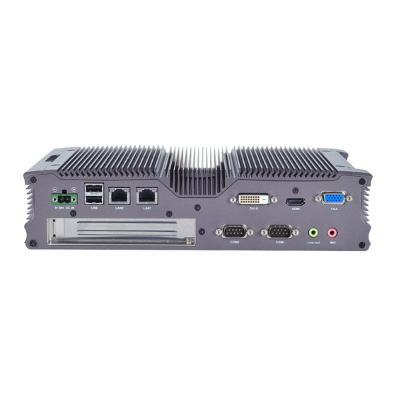
Page 10: Rear Components
System Components Rear Components Component Description Pin Definition Reference R1 DC-In (power) 1x2 Pin Power-in Connector. The LEC-2270 CN4 on page 20 support power range between Phoenix Contact Connector +9~+30V DC-in. R2 Two USB 2.0 Ports An USB type A connector. In addition to... -
Page 11: Chapter 3: Board Layout
Chapter 3 Board Layout Chapter 3: Board Layout Connectors The following picture highlights the location of the COM port and audio expansion card. Refer to the table 3.1 Connector List for more details. sCT3 sCT1 sCT2 sCT4 COM2 COM1 LEK-IOA2 Embedded and Industrial Computing... -
Page 12: External Connectors
Chapter 3 Board Layout External Connectors The following picture highlights the location of system input/output connectors. Refer to the table 3.2 Connector List for more details. VGA1 UsB3 dVId1 LAN1/LAN2 HdMI1 POWER1 UsB1 UsB2 RsT1 LEd1 LEB-2270 Embedded and Industrial Computing... -
Page 13: Internal Connectors And Jumpers
Chapter 3 Board Layout Internal Connectors and Jumpers The following picture highlights the location of internal connectors and jumpers. Refer to the table 3.2 Connector List for more details. MPCIE2 FAN2 LPC1 CMOs2 sPI1 MPCIE1 CMOs1 UsB4 sIM1 FAN1 sO-dIMM FRONT1 LEB-2270 Embedded and Industrial Computing... -
Page 14: Internal Connectors And Jumpers (Backside)
Chapter 3 Board Layout Internal Connectors and Jumpers (backside) The following picture highlights the location of internal connectors and jumpers on the backside of the board. Refer to the table 3.2 Connector List for more details. sATA1 PWR1 MIO1 sATA2 PCIEIO1 LEB-2270 Embedded and Industrial Computing... -
Page 15: Connectors And Jumpers List
COM1 RS232/422/485 Serial Port COM2 RS232/422/485 Serial Port MIO1 Connector for connecting the COM port and audio expansion board to the LEC-2270 main board SCT1/SCT2 Select COM1 Protocol Setting SCT3/SCT4 Select COM2 Protocol Setting Select COM1 Pin No. 9 function Select COM2 Pin No. -
Page 16: Jumper Settings
Chapter 3 Board Layout Jumper Settings SCT1, SCT2: Select COM1 Protocol Setting SCT2 LEK-IOA2 Board SCT1 Microphone-in Audio Jack (CN1) Pin No. Function CO_GNd MIC_INL CO_GNd RS-232 INsULATOR MIC_INR Line-out Audio Jack (CN2) Pin No. Function RS-422 CO_GNd LINOUT-L CO_GNd INsULATOR LINOUT- R RS-485... - Page 17 VLAN filtering. SPI_RI SPI_RI Pin No. Description Fast Ethernet Gigabit Ethernet BI_DA+ MIO1: Connector for connecting the COM port and audio BI_DA- expansion board to the LEC-2270 main board. BI_DB+ BI_DC+ Pin Name Pin Name BI_DC- HdA_BCLK BI_DB- HdA_sYNC BI_DD+...
- Page 18 Chapter 3 Board Layout Front Panel Function Pin Header (FRONT1): It provides The controller contains two modes of operation—a LED signal and button function on the front panel. legacy mode using I/O space, and an AHCI mode using memory space. software that uses legacy mode will not have AHCI capabilities.
- Page 19 Chapter 3 Board Layout System FAN Connector (FAN1/FAN2) Pin Name Pin Name HdA_BCLK FAN1 sATATXN2 HdA_sYNC FAN2 Pin No. description sATATXP2 HdA_RsT COM4_sIN COM2_sIN VCC5 FAN TAC 3 2 1 DVI-D Connector (DVID1): A single link DVI-D Connector PCI/PCIE Expansion connector for PCI or PCIe low profile card (PCIEIO1, on the backside) Pin No.
- Page 20 Chapter 3 Board Layout MPCIE1: Mini-PCIe Connector with SIM Card Reader SIGNAL SIGNAL SIGNAL PEG_RXN11 143 signal signal PEG_TXN11 144 WAKE# VCC3.3 PCIE_RXN2 PEG_RXP11 145 PEG_RXN2 PCIE_CKN2 PEG_TXP11 146 PEG_TXN2 VCC1.5 CLKREQ# UsIM_PWR PCIE_RXP2 147 PEG_RXP2 UIM_dATA PCIE_CKP2 148 PEG_TXP2 PCIE_CLK_N3 UIM_CLK PEG_RXN10 149...
-
Page 21: Chapter 4: Hardware Setup
Portions of the power supply and some internal circuitry remain active until power is removed. Unpower the LEC-2270 and remove the power cord. Unscrew the 4 threaded screws from the top cover. Open the cover. -
Page 22: Wireless Module Installation
Chapter 4 Hardware Setup Wireless Module Installation Align the wireless module’s cutout with the Mini-PCIe slot notch. Insert the wireless module into the connector diagonally. Unlock Lock Hold down the other end of the wireless module and tighten it with the screws. 3G SIM Card Installation Unlink the SIM card reader first by sliding it outward. -
Page 23: Installing The Hard Disk
Chapter 4 Hardware Setup Installing the Hard Disk The system can accommodate one Serial-ATA disk. Follow these steps to install a hard disk into the system: Take out the hard disk tray and fix the hard disk on the tray with 4 mounting screws as illustrated in the following picture. -
Page 24: Connecting Power
Chapter 4 Hardware Setup Connecting Power Wall Mounting Connect the LEC-2270 to a power source. +9~+30V DC-in The product ships with wall mounting kit. To mount your The DC power-in connector comes with a 2-pin terminal product on the wall, follow the instructions below: block for its Phoenix contact. -
Page 25: Appendix A: Terms And Conditions
Appendix A Terms and Conditions Appendix A: RMA Service Terms and Conditions Requesting a RMA# To obtain a RMA number, simply fill out and fax the “RMA Request Form” to your supplier. Warranty Policy The customer is required to fill out the problem code as listed. - Page 26 Appendix A Terms and Conditions RMA Service Request Form When requesting RMA service, please fill out the following form. Without this form enclosed, your RMA cannot be processed. Reasons to Return: Repair(Please include failure details) RMA No: Testing Purpose Company: Contact Person: Phone No.
Need help?
Do you have a question about the LEC-2270 and is the answer not in the manual?
Questions and answers