
Related Manuals for Lanner LEC-7920


Summary of Contents for Lanner LEC-7920
- Page 1 Embedded & Industrial Computing Hardware Platforms for Embedded and Industrial Computing LEC-7920 Preliminary User's Manual >> Publication date:2012-01-17...
- Page 2 Resource Website accordance with the instruction manual, may cause harmful interference to radio communications. Operation Lanner http://www.lannerinc.com of this equipment in a residential area is likely to cause harmful interference in which case the user will be required Product Resources http://assist.lannerinc.com to correct the interference at his own expense.
-
Page 3: Table Of Contents
TTaTTable of Contentsbeable of Conten Chapter 1: Introduction System Specifications ......... . . 4 Package Contents . -
Page 4: Chapter 1: Introduction
Chapter 1 Introduction Chapter 1: Introduction System Specifications Thank you for choosing the LEC-7920. The LEC-7920 features Intel i5/i7 and Celeron processors. It has dual LAN 277x67x190mm as well as DVI-I and DVI-D connectors for high demand of Dimension (WxHxD) (10.91”x2.64”x7.48”) -
Page 5: Package Contents
Chapter 1 Introduction Package Contents Your package contains the following items: LEC-7920 Fanless Embedded System • Power Adapter (P/N: 0P0W075122001) • Wall-Mounting Kit (P/N: SE9ESA900R100) • Drivers and User’s Manual CD (S09OADA15H100) • 2-pin Female Terminal Block (P/N: 04AW20023Z101) •... -
Page 6: Chapter 2: System Components
Chapter 2 System Components Chapter 2: System Components System Drawing Mechanical dimensions of the LEC-7920 Unit: mm 276.52 Embedded and Industrial Computing... - Page 7 Chapter 2 System Components Block Diagram The block diagram depicts the relationships among the interfaces and modules on the motherboard.. Embedded and Industrial Computing...
-
Page 8: Front Components
Chapter 2 System Components Front Components Component Description Pin Definition Reference F1 Power Button with dual LED ATX Power-on button with LEDs: Standby mode in Red; Power-on mode in Green F2 Reset Reset switch SW9 on page 16 F3 Serial Ports Serial ports through the DB-9 CN15, CN16 on page 14 connector;... -
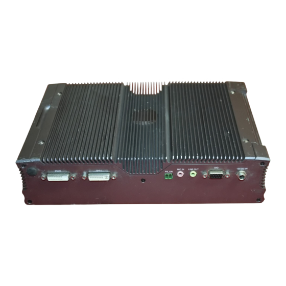
Page 9: Rear Components
R4 DIO Port The DIO port provides 4 digital input CN6 on page 15 and 4 digital output ports. R5 DC-In (power) Connector Power-in Connector. The LEC-7920 DC_IN Connector (CN5) on page supports screw-locked power plug which allows secure power connection. -
Page 10: Chapter 3: Board Layout
Chapter 3 Board Layout Chapter 3: Board Layout External Connectors The following picture highlights the location of system input/output connectors. Refer to the table 3.1 Connector List for more details. CN3/CN4 CN19 CON16 CON15 CN12 LED1 USB1/USB2 CN13/CN14 Embedded and Industrial Computing... -
Page 11: Internal Connectors And Jumpers
Chapter 3 Board Layout Internal Connectors and Jumpers The following picture highlights the location of internal connectors and jumpers. Refer to the table 3.1 Connector List for more details. CN10 CN11 LEB-2220A Embedded and Industrial Computing... -
Page 12: Internal Connectors And Jumpers (Backside)
Chapter 3 Board Layout Internal Connectors and Jumpers (backside) The following picture highlights the location of internal connectors and jumpers on the backside of the board. Refer to the table 3.1 Connector List for more details. Embedded and Industrial Computing... -
Page 13: Connectors And Jumpers List
Chapter 3 Board Layout Connectors and Jumpers List The tables below list the function of each of the board jumpers and connectors by labels shown in the above section. The next section in this chapter gives pin definitions and instructions on setting jumpers. Table 3.1 Connector List for LEB-2220A Labels Function... -
Page 14: Jumper Settings
Chapter 3 Board Layout Jumper Settings RS-232 Serial Port(COM2, CN16): It is a RS-232 port through the D-SUB9 connector. Serial-ATA Connector (J6): It is for connecting a 2.5’’ 1 2 3 4 5 harddisk to be served as your system’s storage. It can support SATA II which features Data transfer rates up to 3.0 Gb/s (300 MB/s). - Page 15 Chapter 3 Board Layout LAN1/LAN2 Ports (CN13/CN14): The LAN ports are Dual USB Port Connector #0 and #1 (USB1): provided by Intel 82574L Ethernet controller whose Dual USB Port Connector #2 and #3 (USB2) interface complies with PCI-e 1.1 (2.5 Ghz). It has advanced management features including IPMI pass-through via SMBus or NC-SI, WOL, PXE remote boot, ISCSI boot and Pin No.
- Page 16 Chapter 3 Board Layout DVI-D Connector (CN1): A single link DVI-D Connector Mini PCI Express Connector (CN9): Pin Name Pin Name WAKE# +3.3V +1.5V Reserved SMB_CLK Reserved PETn0 Pin No. Description Pin No. Description 1.5V SMB_DATA DATA2- DATA2+ CLKREQ# PETp0 RESERVED DDC_CLK DDC_DAT...
- Page 17 Chapter 3 Board Layout DC_IN CONNECTOR (CN5): DC power connector Pin No. Pin Name 12V-IN Embedded and Industrial Computing...
-
Page 18: Chapter 4: Hardware Setup
Portions of the power supply and some internal circuitry remain active until power is removed. Unpower the LEC-7920 and remove the power cord. Note: Turn the device upside down. The system can support memory of DDR3 SO- Unscrew the 4 rubber feet from the bottom cover. -
Page 19: Wireless Module Installation
Chapter 4 Hardware Setup Wireless Module Installation Place the CPU inside the socket and turn the knob all the way until it is horizontally opposite to its original position to lock the CPU securely. Align the wireless module’s cutout with the Mini-PCIe slot notch. -
Page 20: Installing The Hard Disk
Chapter 4 Hardware Setup Installing the Hard Disk Wall Mounting The system can accommodate one Serial-ATA disk. Follow The product ships with wall mounting kit. To mount your these steps to install a hard disk into the system: product on the wall, follow the instructions below: Take out the hard disk tray and fix the hard disk on First make a hole for the anchor in the surface on the the tray with 4 mounting screws as illustrated in the... -
Page 21: Appendix A: Programming Watchdog Timer
Before you could access or control the operation of the watchdog and Digital I/O functions, install the the L_IO The installation process proceeds. Click Close when the driver which is the library and driver needed for Lanner process completes. General Purpose Input/Output interface or functions. - Page 22 View from the menu and select show hidden APIs demonstration. devices . The Lanner common GPIO driver should be listed // History: under the Non-Plug and Play Drivers. If not, click the San for hardware changes button from the tool bar.
- Page 23 Appendix A Programming Watchdog Timer “ F81865_test Sleep milliseconds\n”\ Make sure argument numeric void CheckNumeric (char *szBuf ) “\n”\ nLen strlen (szBuf ) “Argement:\n”\ (int < nLen i++) “ DIO_IN Read state from DIO if (!strchr (“01234567890ABCDEFabcdef”, szBuf[i]) ) In.\n”\ throw “Wrong argument\n”...
- Page 24 Appendix A Programming Watchdog Timer (mWirelessLED , “WirelessLED” WirelessLED) printf (“DIO_IN #%d = %d\n”, nPort, ret) ; return // Check case open int mCaseOpen (int argc, char* argv[]) CHECK_ARGC (2) ; // Milli-second delay int mSleep (int argc, char *argv[]) BOOL bOpen = CaseOpen () ;...
- Page 25 Appendix A Programming Watchdog Timer return nLeft ; // The total argument allowed int num = sizeof (c2f ) / sizeof (c2f[0]) ; // Too few argument // Argument - function mapping if (argc < 2) typedef struct RETMSG (-1, PARAMETER_HELP) char *szCmd ;...
-
Page 26: Appendix B: Digital Input/Output Control On The Gpio Port
Before you could access or control the operation of the watchdog and Digital I/O functions, install the the L_IO driver which is the library and driver needed for Lanner General Purpose Input/Output interface or functions. To install the L_IO driver: Restart the computer, and then log on with Administrator privilege. - Page 27 0, 1, 2 or 3) devices . F81865_test DIO_Out port_number value (writes The Lanner common GPIO driver should be listed Digital output port 0, 1, 2 or 3; For port description, refer under the Non-Plug and Play Drivers. If not, click the to Jumper Settings on Chapter3 Board Layout) San for hardware changes button from the tool bar.
-
Page 28: Appendix G: Terms And Conditions
Appendix G Terms and Conditions Appendix G: RMA Service Terms and Conditions Requesting a RMA# To obtain a RMA number, simply fill out and fax the “RMA Request Form” to your supplier. Warranty Policy The customer is required to fill out the problem code as listed. - Page 29 Appendix G Terms and Conditions RMA Service Request Form When requesting RMA service, please fill out the following form. Without this form enclosed, your RMA cannot be processed. Reasons to Return: Repair(Please include failure details) RMA No: Testing Purpose Company: Contact Person: Phone No.
Need help?
Do you have a question about the LEC-7920 and is the answer not in the manual?
Questions and answers