
Related Manuals for Lanner LEC-2290


Summary of Contents for Lanner LEC-2290
- Page 1 LEC-2290 User Manual Embedded Computing Platform LEC-2290 User Manual Version: 1.0 Date of Release: 2020-11-27...
- Page 2 LEC-2290 User Manual Icon Descriptions The icons are used in the manual to serve as an indication of interest topics or important messages. Below is a description of these icons: Note: This mark indicates that there is a note of interest and is something that you should pay special attention to while using the product.
- Page 3 LEC-2290 User Manual Compliances and Certification This product has passed the CE test for environmental specifications. Test conditions for passing included the equipment being operated within an industrial enclosure. In order to protect the product from being damaged by ESD (Electrostatic Discharge) and EMI leakage, we strongly recommend the use of CE- compliant industrial enclosure products.
- Page 4 LEC-2290 User Manual Ne travaillez pas seul si des conditions dangereuses sont présentes. Ne considérez jamais que l’alimentation est coupée d’un circuit, vérifiez toujours le circuit. Cet appareil génère, utilise et émet une énergie radiofréquence et, s’il n’est pas installé et utilisé conformément aux instructions des fournisseurs de composants sans fil, il risque de provoquer des interférences dans les...
- Page 5 The installation of this product must be performed by trained specialists; otherwise, a non-specialist might create the risk of the system’s falling to the ground or other damages. Lanner Electronics Inc. shall not be held liable for any losses resulting from insufficient strength for supporting the system or use of inappropriate installation components.
- Page 6 LEC-2290 User Manual Un câble de mise à la terre est requis et la zone reliant les sections du conducteur doit faire plus de 4 mm2 ou 10 AWG. Grounding Procedure for Power Source Loosen the screw of the earthing point.
-
Page 7: Table Of Contents
LEC-2290 User Manual Table of Contents Package Content......................... 8 Ordering Information ......................... 8 System Specifications ......................... 9 Front Panel ..........................11 Rear Panel ..........................12 Block Diagram........................... 13 Motherboard Layout ........................ 14 Internal Jumpers and Connector ....................16 Installing the Disk Drive ......................19 Installing 4G Module ........................ -
Page 8: Package Content
LEC-2290 User Manual Package Content Your package contains the following items: 1xLEC-2290 Computer 4x rubber Foot 2x 4-pin Terminal Block, 1x 2-pin Terminal Block, 1x 20-pin Terminal Block Note: If you should find any components missing or damaged, please contact your dealer immediately for assistance. -
Page 9: System Specifications
LEC-2290 User Manual System Specifications Support Intel® Core™ i7-8700(T), i5-8500(T), i3-8100(T) (FCLGA1152), Codenamed Coffee Lake S Up to 3.2 GHz Frequency Processor System 6 core Core Number C246 Chipset Fanless DDR4 2133/2400 SO-DIMM x2 Technology Memory Max. Capacity Up to 32 GB... - Page 10 LEC-2290 User Manual -40° C to +70° C Storage Temperature 10%~90% Relative Humidity 275 x 225 x 115mm (without mounting) Dimension (W x H x D) Mechanical 6.2 kg Weight Wallmount kit Mounting Windows 10 IoT 64-bit series Microsoft Windows OS Support Ubuntu 18.10 64bit above / Cent OS 7 above / Fedora 30 64bit and...
-
Page 11: Front Panel
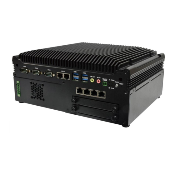
LEC-2290 User Manual Front Panel PoE2 PoE3 PoE4 PoE1 HDD 1 HDD2 Description COM Port 3x DB9 Male Connector for RS232/422/485 GbE Port 2x RJ45 port with LED indicators USB 3.0 Port 4x USB 3.0 Type A Audio Jack 3.5mm Line-out and Line-in Jack... -
Page 12: Rear Panel
LEC-2290 User Manual Rear Panel Description 20 pin terminal block 8 DI (12V)& 8 DO(12V,100mA) Isolation Display Port 1x Display Port HDMI Port 2x HDMI Port COM Port 3x DB9 Male Connector for RS232/422/485 1x 4-pin terminal block for DC 9~36V system power source... -
Page 13: Block Diagram
LEC-2290 User Manual Block Diagram The block diagram indicates how data flows among components on the motherboard. Please refer to the following figure for your motherboard’s layout design. Coffee Lake Intel® Core™ i7 Intel® Core™ i5 Intel® Core™ i3 1x PCIe x16 Slot... -
Page 14: Motherboard Layout
LEC-2290 User Manual Motherboard Layout DDR4 DDR4 JNGFF1 Expansion Storage MSATA1 MPCIE1... - Page 15 LEC-2290 User Manual PCIE2 PCIE1...
-
Page 16: Internal Jumpers And Connector
LEC-2290 User Manual Internal Jumpers and Connector DESCRIPTION DESCRIPTION WAKE# +3.3V RSVD RSVD +1.5V CLKREQ# UIM_PWR UIM_DATA REFCLK- UIM_CLK REFCLK+ UIM_RESET UIM_VPP RSVD RSVD W_DISABLE# PERST# PERn0 +3.3V PERp0 +1.5V SMB_CLK PETn0 SMB_DATA PETp0 USB_D+ USB_D- +3.3V MPCIE +3.3V LED_WWAN#... - Page 17 LEC-2290 User Manual DESCRIPTION DESCRIPTION CONFIG3 3V3_AUX 3V3_AUX CARD PWROFF USB D+ W_DIS USB D- DAS/DSS# KEY B CONFIG0 AUDIO_0 AUDIO_1 AUDIO_2 AUDIO_3 PERn1/USB3RX- UIM_RFU PERp1/USB3RX+ UIM_RESET UIM_CLK PETn1/USB3TX- UIM_DATA PETp1/USB3TX+ UIM_PWR DEVSLP PETn0/SATA_B+ GNSS0 PETp0/SATA_B- GNSS1 GNSS2 PERn0/SATA_A- GNSS3...
- Page 18 LEC-2290 User Manual DESCRIPTION DESCRIPTION +3.3V SATA_RXp +3.3V SATA_RXn SATA_TXn MSATA SATA_TXp +3.3V +3.3V +3.3V...
-
Page 19: Installing The Disk Drive
LEC-2290 User Manual To reduce the risk of personal injury, electric shock, or damage to the unit, please remove all power connections to completely shut down the device. Also, please wear ESD protection gloves when conducting the steps in this chapter. -
Page 20: Installing 4G Module
LEC-2290 User Manual Installing 4G Module This system comes with an external M.2 slot, supporting dual SIM design. The following will discuss the installation of 4G module and SIM cards. Loosen the two screws that secure the tray and draw out the tray by its grip. -
Page 21: Wall Mounting
LEC-2290 User Manual Wall Mounting The system can be mounted on a flat surfaced wall. Please take the following into considerations when mounting the system onto the wall. 1. Fix the wallmount brackets onto the system bottom by securing them with four provided screws. - Page 22 LEC-2290 User Manual On the wall, measure the exact place where you want to hang the system, and drill four holes that match the four mounting holes on both brackets. Insert four anchoring bolts into the holes. Align the four mounting holes on the system’s brackets with the four anchoring bolts you just installed on the wall.
-
Page 23: Entering Bios Setup
LEC-2290 User Manual Entering BIOS The system has AMI BIOS built-in, with a SETUP utility that allows users to configure required settings or to activate certain system features. Pressing the <Tab> or <Del> key immediately allows you to enter the Setup utility. -
Page 24: Main Page
LEC-2290 User Manual Main Page Setup main page contains BIOS information and project version information. Feature Description BIOS Vendor: American Megatrends Core Version: AMI Kernel version, CRB code base, X64 BIOS Compliancy: UEFI version, PI version Information Project Version: BIOS release version... -
Page 25: 2.1 Advanced Page
LEC-2290 User Manual 2.1 Advanced Page Select the Advanced menu item from the BIOS setup screen to enter the “Advanced” setup screen. Users can select any of the items in the left frame of the screen. - Page 26 LEC-2290 User Manual...
- Page 27 LEC-2290 User Manual Feature Options Description Disabled Enable/Disable moving of DRAM contents to PRM C6DRAM Enabled memory when CPU is in C6 state Software Guard Disabled Enable/Disable Software Guard Extensions (SGX) Extensions (SGX) Enabled CPU Flex Ratio Disabled Enable/Disable CPU Flex Ratio Programming...
- Page 28 LEC-2290 User Manual Enabled for Windows XP and Linux (OS optimized for Disabled Hyper-Threading Technology) and Disabled for Hyper-Threading Enabled other OS (OS not optimized for Hyper-Threading Technology). Disabled Enable/Disable BIST (Built-In Self Test) on reset BIST Enabled HALT Loop...
- Page 29 LEC-2290 User Manual Feature Options Description Max Battery Select the performance state that the BIOS Boot performance Max Non-Turbo will set starting from reset vector. mode Performance Turbo Performance" Intel(R) Disabled Allows more than two frequency ranges to be SpeedStep(tm) Enabled supported.
- Page 30 LEC-2290 User Manual Feature Options Description Disabled When Disabled ME will be put into ME Temporarily ME State Enabled Disabled Mode.
- Page 31 LEC-2290 User Manual Feature Options Description Me FW Image Re- Disabled Enable/Disable Me FW Image Re-Flash function. Flash Enabled...
- Page 32 LEC-2290 User Manual Feature Options Description Enables or disables BIOS support for security device. Security Device Enabled By disabling this function, OS will not show Security Support Disabled Device. TCG EFI protocol and INT1A interface will not be available.
- Page 33 LEC-2290 User Manual Feature Options Description Enables or disables BIOS support for security device. Security Device Enabled By disabling this function, OS will not show Security Support Disabled Device. TCG EFI protocol and INT1A interface will not be available. Enables or disables Security Device.
- Page 34 LEC-2290 User Manual...
- Page 35 LEC-2290 User Manual Feature Options Description Enables or disables BIOS support for security device. Security Device Enabled By disabling this function, OS will not show Security Support Disabled Device. TCG EFI protocol and INT1A interface will not be available. Enabled SHA-1 PCR Bank Enables or disables SHA-1 PCR Bank.
- Page 36 LEC-2290 User Manual...
- Page 37 LEC-2290 User Manual Feature Options Description Enabled Serial Port Enables or disables Serial Port 1. Disabled Device Settings IO=3F8h; IRQ = 4...
- Page 38 LEC-2290 User Manual Feature Options Description Enabled Serial Port Enables or disables Serial Port 2. Disabled Device Settings IO=2F8h; IRQ = 3...
- Page 39 LEC-2290 User Manual Feature Options Description Smart Fan Control None Smart Fan Parameters...
- Page 40 LEC-2290 User Manual Feature Options Description Manual Mode Smart Fan Mode Smart Fan Mode select Smart Fan Mode Target Input Target Temperature (Range:0 - 127) Temperature T1 Target Input Target Temperature (Range:0 - 127) Temperature T2 Target Input Target Temperature (Range:0 - 127)
- Page 41 LEC-2290 User Manual Feature Options Description Status LED Green Configures Status LED color...
- Page 42 LEC-2290 User Manual Feature Options Description Output Low Digital I/O Output 1 Configure Digital I/O Pin1 Output High Output Low Digital I/O Output 3 Configure Digital I/O Pin3 Output High Output Low Digital I/O Output 5 Configure Digital I/O Pin5...
- Page 43 LEC-2290 User Manual Feature Options Description Enabled Case Open Enables or disables Case Open function Disabled...
- Page 44 LEC-2290 User Manual Feature Options Description Watch Dog Enabled Enables or disables Watch Dog Timer function Timer Disabled...
- Page 45 LEC-2290 User Manual Feature Options Description COM0 Enabled Console Enables or disables Console Redirection Disabled Redirection...
- Page 46 LEC-2290 User Manual Feature Options Description VT100: ASCII char set VT100 VT100+:Extends VT100 to support color, VT100+ function keys, etc. Terminal Type VT-UTF8 VT-UTF8:Uses UTF8 encoding to map Unicode ANSI chars onto 1 or more bytes ANSI: Extended ASCII char set...
- Page 47 LEC-2290 User Manual None Flow Control can prevent data loss from Flow Control Hardware buffer overflow. RTS/CTS VT-UTF8 Combo Disabled Enables VT-UTF8 Combination Key Support for Key Support Enabled ANSI/VT100 terminals Disabled With this mode enabled, only text will be sent.
- Page 48 LEC-2290 User Manual Feature Options Description Redirection COM COM0 Select a COM port to display redirection of Legacy Port OS and Legacy OPROM Messages. 80x24 On Legacy OS, the Number of Rows and Resolution 80x25 Columns supported redirection. When Bootloader is selected, Legacy Console...
- Page 49 LEC-2290 User Manual...
- Page 50 LEC-2290 User Manual Feature Options Description BME DMA Disabled Re-enable Bus Master Attribute disabled during Pci Mitigation Enabled enumeration for PCI Bridges after SMM Locked Globally Enables or Disables Hot-Plug support for the entire System. If System has Hot-Plug capable...
- Page 51 LEC-2290 User Manual...
- Page 52 LEC-2290 User Manual Feature Options Description Enables Legacy USB support. Enabled Auto option disables legacy support if no Legacy USB Support Disabled USB devices are connected; Auto Disabled option will keep USB devices available only for EFI applications. This is a workaround for OSes without XHCI...
- Page 53 LEC-2290 User Manual Feature Options Description Disabled Network Stack Enables or disables UEFI Network Stack Enabled...
- Page 54 LEC-2290 User Manual Feature Options Description Disabled CSM Support Enables or disables CSM Support Enabled Do Not Launch Controls the execution of UEFI and Legacy Network UEFI PXE OpROM Legacy Do Not Launch Controls the execution of UEFI and Legacy...
- Page 55 LEC-2290 User Manual...
- Page 56 LEC-2290 User Manual Feature Options Description Control Disabled Legacy PXE MGMT Lan1 Control Legacy PXE Boot from which Lan Boot from MGMT Lan2...
-
Page 57: Chipset
LEC-2290 User Manual Chipset Select the Chipset menu item from the BIOS setup screen to enter the Platform Setup screen. Users can select any of the items in the left frame of the screen. - Page 58 LEC-2290 User Manual Feature Options Description Disabled VT-d VT-d capability Enabled Enable/Disable above 4GB MemoryMappedIO BIOS Above 4GB MMIO Disabled assignment This is enabled automatically when Aperture BIOS assignment Enabled Size is set to 2048MB. Disabled X2APIC Opt Out Enable/Disable X2APIC_OPT_OUT bit...
- Page 59 LEC-2290 User Manual...
- Page 60 LEC-2290 User Manual Feature Options Description Auto Maximum Memory 1067 Maximum Memory Frequency Selections in Mhz. Valid Frequency values should match the refclk, i.e. divide by 133 or 100 3200 Dynamic Maximum Value of TOLUD. Dynamic assignment would 1 GB...
- Page 61 LEC-2290 User Manual...
- Page 62 LEC-2290 User Manual Feature Options Description Disabled Enable Root Port Enabled Enable or Disable the Root Port Auto Auto Gen1 Max Link Speed Configure PEG 0:1:0 Max Speed Gen2 Gen3 Sets the upper limit on power supplied by slot. Power limit...
- Page 63 LEC-2290 User Manual Feature Options Description Detect Non- Disabled Detect Non-Compliance PCI Express Device in PEG Compliance Device Enabled...
- Page 64 LEC-2290 User Manual Feature Options Description Serial IRQ Quiet Configure Serial IRQ Mode. Mode Continuous Power On Restore AC Specify what state to go to when power is re-applied after a Power Off Power Loss power failure (G3 state). Last State...
- Page 65 LEC-2290 User Manual...
- Page 66 LEC-2290 User Manual Feature Options Description PCI Express Root Disabled Control the PCI Express Root Port. Port 9 Enabled Disabled Set the ASPM Level: Force L0s - Force all links to L0s ASPM 8 State AUTO - BIOS auto configure DISABLE - Disables...
- Page 67 LEC-2290 User Manual Feature Options Description Enabled SATA Controller(s) Enable/Disable SATA Device. Disabled SATA Mode AHCI Determines how SATA controller(s) operate. Selection Intel RST Aggressive LPM Enabled Enable PCH to aggressively enter link power state. Support Disabled Enabled Port 2...
- Page 68 LEC-2290 User Manual Feature Options Description Disabled Enable will lock bytes 38h-3Fh in the lower/upper RTC Memory Lock Enabled 128-byte bank of RTC RAM Enable/Disable the PCH BIOS Lock Enable feature. Disabled BIOS Lock Required to be enabled to ensure SMM Enabled protection of flash.
-
Page 69: Security
LEC-2290 User Manual Security Select the Security menu item from the BIOS setup screen to enter the Security Setup screen. Users can select any of the items in the left frame of the screen. Feature Description If ONLY the Administrator's password is set, it only limits... - Page 70 LEC-2290 User Manual Feature Options Description Secure Boot is activated when Platform Key(PK) is Secure Boot Disabled enrolled, System mode is User/Deployed, and CSM Enable Enabled function is disabled. Customizable Secure Boot mode: In Custom mode, Secure Boot Standard Secure Boot Policy variables can be configured by...
- Page 71 LEC-2290 User Manual Feature Options Description Factory Key Disabled Provision factory default keys on next re-boot only Provision Enabled when System in Setup Mode. Force System to User Mode. Configure NVRAM to Restore Factory None contain OEM-defined factory default Secure Boot keys keys.
-
Page 72: Boot Menu
LEC-2290 User Manual Boot Menu Select the Boot menu item from the BIOS setup screen to enter the Boot Setup screen. Users can select any of the items in the left frame of the screen. Feature Options Description The number of seconds to wait for setup Setup Prompt Timeout activation key. -
Page 73: Save And Exit Menu
Save and Exit Menu Select the Save and Exit menu item from the BIOS setup screen to enter the Save and Exit Setup screen. Users can select any of the items in the left frame of the screen. ■ Discard Changes and Exit Select this option to quit Setup without saving any modifications to the system configuration. - Page 74 LEC-2290 User Manual ■ Restore Defaults Restore default values for all setup options. Select “Yes” to load Optimized defaults. PS: The items under Boot Override were not same with image. It should depend on devices connect on system.
- Page 75 LEC-2290 User Manual The status explanations of LED indicators on the Front Panel are as follows: [Status ] System Power/WWAN [Gbe Port] Speed Speed/Link HDD Activity/WLAN [PoE Port] Link/Activity /W/WLANLAN System Power Solid Green The system is powered on The system is powered off...
- Page 76 LEC-2290 User Manual 1. Make sure your system is turned off. 2. Follow the wiring definition and illustration below to connect the power source to the system through the 4-pin terminal block connector as DC Input. Connect the two Power Wires to the Terminal Block (supplied along with the system) by respectively inserting the red wire to the Positive contact, the other wire to the Negative contact, and then secure them onto the terminal block.
- Page 77 LEC-2290 User Manual 4. System with nVidia Graphic Card Burn-in Verification: LEC-2290 + graphic card N1050TI-L9FX (75W) with fan; operating temperature @ 0° C~55° C (35W CPU) / 0° C~45° C (65W CPU) LEC-2290 + graphic card N206S-V9FX (120W) with fan; operating temperature @ 0° C~50° C (35W ...
-
Page 78: Warranty Policy
LEC-2290 User Manual Warranty Policy 1. All products are under warranty against defects in materials and workmanship for a period of one year from the date of purchase. 2. The buyer will bear the return freight charges for goods returned for repair within the warranty period;... -
Page 79: Rma Service Request Form
LEC-2290 User Manual RMA Service Request Form When requesting RMA service, please fill out the following form. Without this form enclosed, your RMA cannot be processed.
Need help?
Do you have a question about the LEC-2290 and is the answer not in the manual?
Questions and answers