
Related Manuals for Lanner LEC-2137B


Summary of Contents for Lanner LEC-2137B
- Page 1 Embedded Computing LEC-2137 User Manual Version: 1.1 Date of Release: 2018-08-27...
- Page 2 Warning: This exclamation point indicates that there is a caution or warning and it is something that could damage your property or product. The listed websites are links to the on-line product information and technical support. Resources Lanner http://www.lannerinc.com Product Resource http://www.lannerinc.com/download-center http://eRMA.lannerinc.com...
- Page 3 This product has passed the CE test for environmental specifications. Test conditions for passing included the equipment being operated within an industrial enclosure. In order to protect the product from being damaged by ESD (Electrostatic Discharge) and EMI leakage, we strongly recommend the use of CE-compliant industrial enclosure products.
- Page 4 LEC-2137 User Manual Risk of Explosion if Battery is replaced by an incorrect type. Dispose of used batteries according to the instructions. Installation only by a trained electrician or only by an electrically trained person who knows all English Installation and Device Specifications which are to be applied. Do not carry the handle of power supplies when moving to another place.
- Page 5 Reliable earthing should be maintained. Particular attention should be given to supply connections other than direct connections to the branch circuit (e.g. use of power strips). Lanner Electronics Inc. shall not be held liable for any losses resulting from insufficient strength for supporting the unit or use of inappropriate installation components.
- Page 6 LEC-2137 User Manual L’équipement électrique génère de la chaleur. La température ambiante peut ne pas être adéquate pour refroidir l’équipement à une température de fonctionnement acceptable sans circulation adaptée. Vérifiez que votre site propose une circulation d’air adéquate. Vérifiez que le couvercle du châssis est bien fixé. La conception du châssis permet à l’air de refroidissement de bien circuler.
- Page 7 Version Date Descriptions 2018/04/03 Official Release 2018/08/27 Modified R6 Reset Button definition...
- Page 8 LEC-2137 User Manual Package Content ......................... 10 Ordering Information ......................... 11 System Specifications ......................... 11 Front Panel ..........................13 Rear Panel ........................... 14 Block Diagram ..........................15 Motherboard Layout ........................18 Internal Jumper & Connectors ....................19 Opening the Chassis ........................22 Remove the PoE Power Board ....................
- Page 9 Boot Menu ..........................57 Save and Exit Menu ........................58 Warranty Policy .......................... 63 RMA Service ..........................63 RMA Service Request Form ......................64...
- Page 10 LEC-2137 User Manual The LEC-2137 is a fanless and robust embedded box PC system utilizing the Intel Apollo Lake CPU with improved graphical and media performance, including support USB 3.0, Low-powered DDR3/L and VGA/HDMI display. The system is ideal for efficient imaging workflows, digital signage with secure content delivery, visually appealing interactive clients (interactive kiosks, intelligent vending, ATM and point-of-sale (POS) terminals) and industrial control systems.
-
Page 11: Chapter 1: Product Overview
Chapter 1: Product Overview SKU No. LEC-2137A Intel E3950 4 Cores+6x GbE LEC-2137B Intel E3950 4 Cores+2x GbE+ 4x PoE LEC-2137C Intel N3350 2 Cores+6x GbE LEC-2137D Intel N3350 2 Cores+2x GbE+ 4x PoE Intel® Atom™ x7-E3950 or Celeron® N3350 Base frequency 1.6 GHz/1.1 GHz... -
Page 12: Driver Support
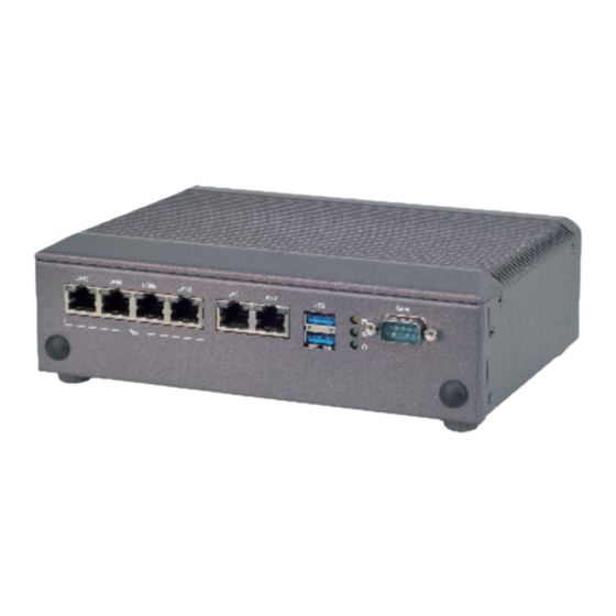
PoE ports supplying 54.405W power to 4x IP cameras) AC to DC, AC 90 to 240 VAC Input Power Adaptor DC 24VDC/2.5A 60W /120W LEC-2137A/LEC-2137B: -20°C to 55°C Operating Temperature LEC-2137C/LEC-2137D: 0°C to 50°C Storage Temperature -20°C to 70°C Environment... - Page 13 Chapter 1: Product Overview Description 6 x 100/1000Mbps Ethernet ports or GbE & PoE Ports 4x 100/1000Mbps PoE ports + 2x 100/1000Mbps Ethernet ports (by SKU) USB Port 2x USB 3.0 port HDD Activity WWAN Connection Status System Power LED Indicators Please refer to Appendix A: LED Indicator Explanations for description of the LED Indicators (including those on GbE Ports and Power Button) 1x DB9 Male connector, RS-232/422/485...
- Page 14 LEC-2137 User Manual 一 Description Power Button 1x Power button with LED USB Port 2x USB 2.0 port 1x HDMI with screw HDMI Port 1x DB9 Male connector, RS-232/422/485 Serial Port Power Supply DC 24VDC, 2.5A 60W/120W, 2-pin terminal block Hardware reset Reset Button...
-
Page 15: Chapter 2: Motherboard Information
Chapter 2: Motherboard Information The block diagram indicates how data flows among components on the motherboard. Please refer to the following figure for your motherboard’s layout design. - Page 16 LEC-2137 User Manual...
- Page 17 Chapter 2: Motherboard Information...
- Page 18 LEC-2137 User Manual The motherboard layout shows the connectors and jumpers on the board. Refer to the following picture as a reference of the pin assignments and the internal connectors.
- Page 19 Chapter 2: Motherboard Information MSATA1 17 15 18 16 Description Description Description Description WAKE# +3.3Vaux COEX1 COEX2 +1.5V CLKREQ# UIM_PWR UIM_DATA REFCLK+ UIM_CLK REFCLK- UIM_RESET UIM_VPP Reserve Reserve W_DISABLE# PERST# PERn0 +3.3Vaux PERp0 +1.5V SMB_CLK PETn0 SMB_DATA PETp0 USB_D- USB_D+ +3.3Vaux +3.3Vaux LED_WWAN#...
- Page 20 LEC-2137 User Manual MPCIE1: Mini-PCIe socket with SIM card reader Description Description Description Description WAKE# +3.3Vaux COEX1 COEX2 +1.5V CLKREQ# UIM_PWR UIM_DATA Reserve UIM_CLK Reserve UIM_RESET UIM_VPP Reserve Reserve W_DISABLE# PERST# Reserve +3.3Vaux Reserve +1.5V Reserve Reserve Reserve Reserve USB_D- USB_D+ +3.3Vaux +3.3Vaux...
- Page 21 Chapter 2: Motherboard Information JRI1 (Pin Header) Setting Description 1-2 (Default): RI# 3-4: +5V 5-6: +12V JSPI1 (Pin Header) Description Description HOLD# +1.8V MISO MOSI JCMOS1 & 2: (Pin Header) Setting Description Setting Description 1-2: 2-3: CMOS2 Normal (Default) Clear CMOS CMOS1 Note: For your selection of CMOS function to work (Normal or Clear CMOS), please make sure you have configured both the settings on both CMOS1 and CMOS2.
- Page 22 LEC-2137 User Manual To reduce the risk of personal injury, electric shock, or damage to the unit, please remove all power connections to completely shut down the device. Also, please wear ESD protection gloves when conducting the steps in this chapter. 1.
-
Page 23: Chapter 3: Hardware Setup
Chapter 3: Hardware Setup As certain components and connectors such as the SODIMM slot are topped by the PoE Power board, you will have to remove this board in order to reach these components. Simply remove the four screws that lock the board to the motherboard to reveal the covered components. PoE Power Board... - Page 24 LEC-2137 User Manual The motherboard supports SODIMM memory. Please follow the steps below to install the SODIMM memory modules. 1. Follow the instructions in Remove the PoE Power Board to reveal the SODIMM slot. 2. Align the notch of the module with the socket key in the slot. 3.
- Page 25 Chapter 3: Hardware Setup The motherboard provides one mSATA slot. Follow the procedures below for installing an mSATA card. 1. Locate the mSATA slot. 2. Align the notch of the mSATA module with the socket key in the slot, and insert it at 30 degrees into the socket until it is fully seated in the connector.
- Page 26 LEC-2137 User Manual 1. Locate MPCIE1 slot. To install the SIM card: 2. Slide open the socket cover and lift the cover on its hinges. 3. Insert the SIM card into the slot in the cover with the gold contacts facing down, and the angled corner of the card is positioned correctly as shown in the picture.
- Page 27 Chapter 3: Hardware Setup To install the 3G module 5. Align the notch of the module with the socket key in the slot, and insert it at 30 degrees into the socket until it is Socket Notch fully seated in the connector. 6.
- Page 28 LEC-2137 User Manual 1. Fix the hard disk onto the inner side of the bottom panel with provided disk screws. 2. Insert the end of the SATA cable to the SATA contacts on the disk. 3. Insert the other end of the SATA data cable to the SATA port on the motherboard and the end of the SATA power cable to the SATA Power port.
-
Page 29: Chapter 4: Bios Setup
Chapter 4: BIOS Setup To enter the BIOS setup utility, simply follow the steps below: 1. Boot up the system. 2. Pressing the <Tab> or <Del> key immediately allows you to enter the Setup utility, then you will be directed to the BIOS main screen. 3. - Page 30 LEC-2137 User Manual Setup main page displays a description of BIOS information and project version information. You can also set up the System Time and System Date here. (The screenshots presented in section are for reference only) Item Description The option allows the user to set the date on the system RTC. System Date Simply navigate to the month, day, or year and type in the correct numeric value.
- Page 31 Chapter 4: BIOS Setup Use [←] / [→] to select [Advanced] setup screen. Under this screen, you may use [↑] [↓] to select an item you want to configure.
- Page 32 LEC-2137 User Manual This option allows you to turn on/off the BIOS support for security device. Press <Enter> to access the submenu. The default is “Enabled”.
- Page 33 Chapter 4: BIOS Setup This option allows you to configure parameters about Super IO Chip. Press “Enter “ to access the submenu.
- Page 34 LEC-2137 User Manual Serial port 1 Configuration Item Value Description Serial Port Enabled Enable or Disable Serial Port 1. Disabled Device Settings IO=3F8h; IRQ = 4 RS232 Com1 MODE RS485 Select Com Mode as RS232/RS485/RS422. RS422...
- Page 35 Chapter 4: BIOS Setup This option allows you to monitor the PC Health status. Item Description CPU Temp This value reports the CPU temperature. system Temp This value reports the overall System temperature. CPU VCORE This value reports the CPU VCORE. VSB5V This value reports the VSB5V Input voltage.
- Page 36 LEC-2137 User Manual This option allows you to enable or disable Watchdog Timer function. The default is “Disabled”. Item Value Description Enabled Watch Dog Timer Enable or Disable Watch Dog function Disabled Second Mode Timer Count Mode Select Second Mode or Minute Mode Minute Mode Timer out Value 1~255...
- Page 37 Chapter 4: BIOS Setup This option allows you to configure PoE GPIO pin output setting. Item Value Description Output Low POE GPIO Pin 1 Configuration POE GPIO Pin 1 Output High Output Low POE GPIO Pin 2 Configuration POE GPIO Pin 2 Output High Output Low POE GPIO Pin 3...
- Page 38 LEC-2137 User Manual This option allows you to configure parameters about serial port console redirection. Press “Enter “to access the submenu. The default is “Enabled”. Item Value Description Disabled Console Redirection Console Redirection Enabled or Disabled Enabled...
- Page 39 Chapter 4: BIOS Setup Console Redirection Settings Select this item to enter the setting sub-menu. These settings specify how the host computer and the remote computer will exchange data. Both computers should have the same or compatible settings. Item Value Description ANSI: Extended ASCII char set.
- Page 40 LEC-2137 User Manual Mark Space Stop bits indicate the end of a serial data Stop Bits packet. Flow control can prevent data loss from buffer None Flow Control overflow. Hardware RTS/CTS Enable VT-UTF8 Combination Key Support for VT-UTF8 Combo Key Disabled ANSI/VT100 terminals Support...
- Page 41 Chapter 4: BIOS Setup This option allows you to configure socket specific CPU information.
- Page 42 LEC-2137 User Manual Socket 0 CPU Information...
- Page 43 Chapter 4: BIOS Setup CPU Power Management Configuration Item Value Description Disabled EIST Enable/Disable Intel SpeedStep Enabled Disabled Turbo Mode Enable/Disable Turbo mode Enabled...
- Page 44 LEC-2137 User Manual This option allows you to enable or disable ROM execution settings. Item Value Description Disabled Enable/Disable CSM Support CSM Support Enabled Do Not Launch Controls the execution of UEFI and Legacy Network UEFI PXE OpROM Legacy Do Not Launch Controls the execution of UEFI and Legacy Storage UEFI...
- Page 45 Chapter 4: BIOS Setup This option allows you to change USB configuration parameters. Legacy USB Support Item Value Description Enables Legacy USB support. “Auto“ disables legacy support if no USB devices are connected. Auto Legacy USB Support Enabled “Disabled“ will keep USB devices available only Disabled for EFI applications.
- Page 46 LEC-2137 User Manual Item Value Description Select On-Board LAN for enabling PXE boot PXE Function LAN1 function. Disabled...
- Page 47 Chapter 4: BIOS Setup Item Value Description Enable/Disable EIST. GV3 and TM1 must be enabled for TM2 to be available. GV3 must be Disable EIST(GV3) enabled for Turbo. Auto - Enable for B0 CPU Enabled stepping, all others disabled, change setting to override.
- Page 48 LEC-2137 User Manual...
- Page 49 Chapter 4: BIOS Setup This option enables or disables fast boot which skips memory training and attempts to boot using last known good configuration. The default is “Enabled”. Item Value Description 2 GB 2.25 GB Maximum Value of TOLUD Max TOLUD 2.5 GB 2.75 GB 3 GB...
- Page 50 LEC-2137 User Manual Item Value Description Windows Android OS Selection Select the target OS Win 7 Intel Linux...
- Page 51 Chapter 4: BIOS Setup...
- Page 52 LEC-2137 User Manual SATA Driver...
- Page 53 Chapter 4: BIOS Setup Miscellaneous Configuration Item Value Description Disabled High Precision Timer Enable or Disable the High Precision Event Timer Enabled Specify what state to go to when power is Power On Restore AC Power re-applied after a power failure (G3 State). S0 Power Off Loss state: System will boot directly as soon as power...
- Page 54 LEC-2137 User Manual Use [←] / [→] to select [Security] setup screen. Under this screen, you may use [↑] [↓] to select an item you would like to configure. Administrator Password & User Password: Item Description Administrator If ONLY the Administrator's password is set, then this only limits access to Password Setup and is only asked for when entering Setup.
- Page 55 Chapter 4: BIOS Setup Secure Boot Enter Secure Boot page for more related settings. Item Value Description Secure Boot activated when Platform Key(PK) is Disabled Attempt Secure Boot enrolled, System mode is User/Deployed, and Enabled CSM function is disabled Secure Boot mode selector: Standard Secure Boot Mode In Custom mode, Secure Boot Variables can be...
- Page 56 LEC-2137 User Manual Key Management Item Value Description Provision Factory Disabled Allow to provision factory default Secure Boot Defaults Enabled keys when System is in Setup Mode. Install Factory Default Force System to User Mode - install all Factory None keys Default keys Allow the image to run in Secure Boot mode.
- Page 57 Chapter 4: BIOS Setup Select the Boot menu item from the BIOS setup screen to enter the [Boot] Setup screen. Description Item Value Disabled Quiet Boot Enables or disables Quiet Boot option. Enabled LEGACY Boot mode select Select boot mode LEGACY/ UEFI. UEFI...
- Page 58 Select the Save and Exit menu item from the BIOS setup screen to enter the [Save and Exit] Setup screen. Users can select any of the items in the left frame of the screen. Save Changes and Exit When you have completed the system configuration, select this option to save the changes and Exit from BIOS Setup, so the new system configuration parameters can take effect.
-
Page 59: Wwan Connection
Appendix A: LED Indicator Explanations The status explanations of LED indicators on Front Panel are as follows: Power-Off mode: Stand-by mode: Power-On mode: The system is not connected to any The system is connected with power The system is powered on. Perform a power source. -
Page 60: Watchdog Timer
LEC-2137 User Manual A watchdog timer is a piece of hardware that can be used to automatically detect system anomalies and reset the processor in case there are any problems. Generally speaking, a watchdog timer is based on a counter that counts down from an initial value to zero. The software selects the counter’s initial value and periodically restarts it. -
Page 61: Appendix C: Setting Up Console Redirections
Appendix C: Setting up Console Redirections Console redirection lets you monitor and configure a system from a remote terminal computer by re-directing keyboard input and text output through the serial port. The following steps illustrate how to use this feature. The BIOS of the system allows the redirection of the console I/O to a serial port. With this configured, you can remotely access the entire boot sequence through a console port. - Page 62 LEC-2137 User Manual To install the Intel® LAN controller base driver for the Red Hat® and Linux operating system, please visit http://www.lannerinc.com/support/download-center/drivers, enter the product category and download the utility package of LEC-2137. For the latest driver update, please visit Intel® download center at https://downloadcenter.intel.com/, use the keyword search or the filter to access the driver’s product page, and then download the latest controller driver as well as the ReadMe document.
-
Page 63: Appendix E: Terms And Conditions
Appendix E: Terms and Conditions 1. All products are under warranty against defects in materials and workmanship for a period of one year from the date of purchase. 2. The buyer will bear the return freight charges for goods returned for repair within the warranty period; whereas the manufacturer will bear the after service freight charges for goods returned to the user. - Page 64 LEC-2137 User Manual When requesting RMA service, please fill out the following form. Without this form enclosed, your RMA cannot be processed.
Need help?
Do you have a question about the LEC-2137B and is the answer not in the manual?
Questions and answers