
Related Manuals for Lanner LEC-7230


Summary of Contents for Lanner LEC-7230
- Page 1 Embedded & Industrial Computing Hardware Platforms for Embedded and Industrial Computing LEC-7230 V1.2 User's Manual >> Release date: 2016/10/31...
- Page 2 2014/05/12 Official release 2016/09/01 -Modify the Appendices for new This document is copyrighted, © 2014. All rights are Lanner GPIO driver installation reserved. The original manufacturer reserves the right to -Add the Hardware Installation make improvements to the products described in this chapter manual at any time without notice.
- Page 3 EMC Notice Operating Safety • Electrical equipment generates heat. Ambient air temperature may not be adequate to cool equipment to This equipment has been tested and found to comply acceptable operating temperatures without adequate with the limits for a Class A digital device, pursuant to Part circulation.
-
Page 4: Table Of Contents
Table of Contents Chapter 1: Introduction System Specifications Package Contents Standard Accessories Optional Power Cords Optional Mounting Kit Optional Accessories Chapter 2: System Components System Drawing Block Diagram Front Components Rear Components Chapter 3: Motherboard Layout Connectors and Jumpers List Jumper and Connectors Chapter 4: Hardware Setup Preparing the Hardware Installation... -
Page 5: Chapter 1: Introduction
Introduction System Specifications Intel® Celeron® J1900/N2930/ Processor Options E3825/E3845 CPU Thank you for choosing the LEC-7230. The LEC-7230 BIOS AMI SPI Flash BIOS features Intel Celeron J1900/N2930/E3825/E3845 processor. The system supports dual LAN as well as HDMI 1 x SO-DIMM socket for up to... -
Page 6: Package Contents
Package Contents Your package contains the following items: LEC-7230 Fanless Embedded System • Power adapter (P/N: 0P0W060122002) • Drivers and User’s Manual CD : S09OADA64H110 • 2-pin Terminal Block (P/N: 04AW20023Z101) • 6-pin Terminal Block (P/N: 04AW20061Z101) • Standard Accessories 0P0W060122002 AC Power Adapter 60W 12V/5A, 2.5mm DC Jack with... -
Page 7: Chapter 2: System Components
Chapter 2: System Components System Drawing Mechanical dimensions of the LEC-7230 Unit: mm... -
Page 8: Block Diagram
Block Diagram... -
Page 9: Front Components
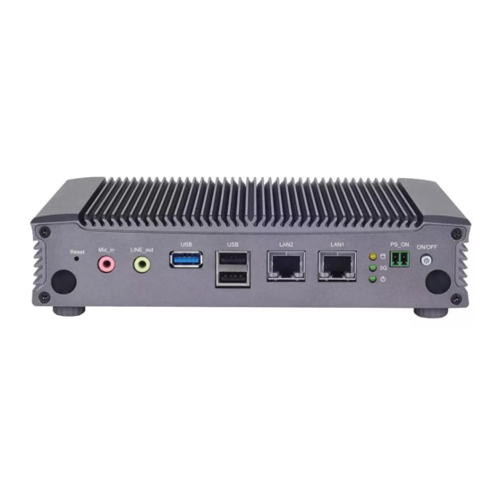
Front Components Component Description F1 Reset Reset switch F2 MIC IN/LINE OUT Connect the audio devices to these ports. The Microphone and line out port are provided by Realtek ALC 886-GR. F3 USB 3.0 Port An USB 3.0 type A connector. F4 Four USB 2.0 Ports Double-stacked USB 2.0 type A connectors Two additional USB 2.0 ports by LEK-IOA11. -
Page 10: Rear Components
R5 Power Adapter Socket DC-in 12V. Only use the power adapter supplied with the LEC-7230-CT1 System WARNING: Improper installation can cause injury or property damage. For proper and safe operation use in field site with AC Power, please follow these instructions: 1. -
Page 11: Chapter 3: Motherboard Layout
Chapter 3: Motherboard Layout... -
Page 13: Connectors And Jumpers List
Connectors and Jumpers List The tables below list the function of each of the board jumpers and connectors by labels shown in the above section. The next section in this chapter gives pin definitions and instructions on setting jumpers. Table 3.1 Connector List for LEB-7230 Board Labels Function Notes... -
Page 14: Jumper And Connectors
Jumper and Connectors Select COM1/COM2 Pin 9 Function (JRI1/JRI2): The pin 9 of COM1 and COM2 can be altered by JRI1 and JRI2 RS-232/422/485 Serial Port (COM1 and COM2): It is respectively according to the following jumper settings. an RS-232/422/485 port with automatic hardware flow JRI1: COM1 JRI2: COM2 control through a D-SUB9 connector. - Page 15 Clear CMOS jumper (JCMOS1): It is for clearing the Serial-ATA Connector (SATA1): It is for connecting a 2.5’’ CMOS settings. harddisk to serve as your system’s storage. It can support SATA II which features Data transfer rates up to 3.0 Gb/s (300 MB/s).
- Page 16 Mini PCI Express Connector (for 3G card with PCI Express 1X PS/2 Keyboard and Mouse Connector (JKBMS1) and USB 2.0 signals and a SIM card reader, MPCIE1): signal signal WAKE# +3.3Vaux COEX1 COEX2 +1.5V CLKREQ# UIM_PWR UIM_dATA REFCLK- UIM_CLK REFCLK+ UIM_REsET UIM_VPP Pin NO.
- Page 17 Digital Input/Output Connector (DIO1) SIM Card Reader (SIM1) CompactFlash (CF1)
-
Page 18: Chapter 4: Hardware Setup
Portions of the power supply and some internal circuitry remain active until power is removed. 1. Unpower the LEC-7230 and remove the power cord. 2. Turn the device upside down. 3. Unscrew the 4 rubber feet from the bottom cover. -
Page 19: Installing The Wireless Module
2. Insert the wireless module into the connector 1. Align the mounting holes of the HDD/SSD and diagonally. that on the LEC-7230 systems as illustrated in the following picture. Fix the hard disk on the system by 3. Fix the wireless module with the screws. -
Page 20: Installing Compactflash Card
Installing CompactFlash Card 2. Since we are installing Windows 7 operating system on LEC-7230 provides one CompactFlash slot. Follow the a CompactFlash card, which is ATA-based, please change procedures below for installing a CompactFlash card. the “SATA Mode” from “AHCI Mode” to “IDE Mode”. -
Page 21: Appendix A: Programming Watchdog Timer
Appendix A: Programming Watchdog Timer A watchdog timer is a piece of hardware that can be used to automatically detect system anomalies and reset the processor in case there are any problems. Generally speaking, a watchdog timer is based on a counter that counts down from an initial value to zero. -
Page 22: Appendix B: Digital Input/Output Control On The Gpio Port
Before you could access or control the operation of the watchdog and Digital I/O functions, install the DIO driver The current version of Lanner DIO driver is V101. The older version needs to be uninstalled before the current one can be installed. - Page 23 Executing the Sample Program: 7. Confirm the installation. 1. Execute the GPIO demo program at start menu. 8. Installation completed. 2. Program launched. DIO: D-IN: Check the box to alter the voltage level of the digital input pins as to enable or disable the input pins. The default value for D-in is 1 which indicates the high level.
-
Page 24: Appendix C: Terms And Conditions
Appendix C: RMA Service Requesting a RMA# Terms and Conditions 6. To obtain a RMA number, simply fill out and fax the “RMA Request Form” to your supplier. Warranty Policy 7. The customer is required to fill out the problem code as listed.
Need help?
Do you have a question about the LEC-7230 and is the answer not in the manual?
Questions and answers