
Related Manuals for Lanner LEC-7338


Summary of Contents for Lanner LEC-7338
- Page 1 Embedded Computing LEC-7338 User Manual Version: 1.0 Date of Release: 2018-03-28...
- Page 2 LEC-7338 User Manual The icons are used in the manual to serve as an indication of interest topics or important messages. Below is a description of these icons: Note: This check mark indicates that there is a note of interest and is something that you should pay special attention to while using the product.
- Page 3 This product has passed the CE test for environmental specifications. Test conditions for passing included the equipment being operated within an industrial enclosure. In order to protect the product from being damaged by ESD (Electrostatic Discharge) and EMI leakage, we strongly recommend the use of CE-compliant industrial enclosure products.
- Page 4 LEC-7338 User Manual Risk of Explosion if Battery is replaced by an incorrect type. Dispose of used batteries according to the instructions. Installation only by a trained electrician or only by an electrically trained person who knows all English Installation and Device Specifications which are to be applied.
- Page 5 Reliable earthing should be maintained. Particular attention should be given to supply connections other than direct connections to the branch circuit (e.g. use of power strips). Lanner Electronics Inc. shall not be held liable for any losses resulting from insufficient strength for supporting the unit or use of inappropriate installation components.
- Page 6 LEC-7338 User Manual L’équipement électrique génère de la chaleur. La température ambiante peut ne pas être adéquate pour refroidir l’équipement à une température de fonctionnement acceptable sans circulation adaptée. Vérifiez que votre site propose une circulation d’air adéquate. Vérifiez que le couvercle du châssis est bien fixé. La conception du châssis permet à l’air de refroidissement de bien circuler.
- Page 7 Version Date Descriptions 2018/03/28 Official Release...
- Page 8 LEC-7338 User Manual Package Content ......................... 10 Ordering Information ......................... 10 System Specifications ......................... 11 Front Panel ..........................13 Rear Panel ........................... 14 Block Diagram ..........................15 Motherboard Layout ........................17 Internal Jumper & Connectors ....................18 Opening the Chassis ........................21 Installing the System Memory ....................
- Page 9 Save and Exit Menu ........................48 Warranty Policy .......................... 53 RMA Service ..........................53 RMA Service Request Form ......................54...
- Page 10 LEC-7338 User Manual LEC-7338 is a cost effective embedded system which adopts Intel Bay trail CPU to provide a high performance with low power consumption structure and featured with 8-port PoE (power over Ethernet) Ethernet switch. LEC-7338, a compact design supports many integrated multimedia and IO features such a video, network, serial communication, PoE, especially for Network Video Recorder physical security applications.
-
Page 11: Chapter 1: Product Overview
Chapter 1: Product Overview Intel® Celeron® J1900 2 GHz Frequency Core Number Processor System AMI 32Mbit SPI Flash BIOS BIOS Chipset Fanless DDR3L 1333MHz Technology Memory Max. Capacity 1x 204-pin SODIMM Socket Intel® HD Graphics Controller Graphic 1x HDMI, 1920 x 1080 HDMI Realtek ALC886 Realtek ALC886... - Page 12 LEC-7338 User Manual Power Consumption (Idle) Power Consumption (Full Load) 0°C to 50°C Operating Temperature -20°C to 70°C Storage Temperature Environment 5% to 95%, non-condensing Relative Humidity IEC 60068-2-64, 0.5Grms, random 5 Vibration ~500 Hz, 40 mins/axis 272 x 44 x 164.4 mm...
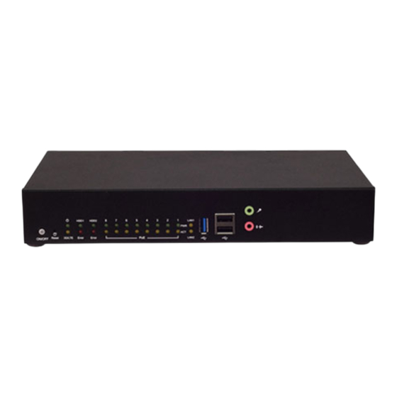
- Page 13 Chapter 1: Product Overview Description Power Button 1x Power button with LED Reset Button Software reset System Power HDD Status PoE Status LAN Port Status LED Indicators HDD Error Data Link Activity /WWAN Data Link Activity USB Port 1x USB 3.0 port USB Port 2x USB 2.0 port Mic-in...
- Page 14 LEC-7338 User Manual Description 1x HDMI Connector HDMI Port 1x 18-pin terminal block for 8DI/8DO Digital IO COM Port 2x DB9 (Male connector supporting RS232/485) Ethernet Port 2x RJ-45 of 10/100/1000Mbps Ethernet ports PoE Port 8x RJ-45 of 10/100Mbos PoE Ethernet Switch ports...
-
Page 15: Chapter 2: Motherboard Information
Chapter 2: Motherboard Information The block diagram indicates how data flows among components on the motherboard. Please refer to the following figure for your motherboard’s layout design. Continued on next page... - Page 16 LEC-7338 User Manual Continued from previous page...
- Page 17 Chapter 2: Motherboard Information The motherboard layout shows the connectors and jumpers on the board. Refer to the following picture as a reference of the pin assignments and the internal connectors.
- Page 18 LEC-7338 User Manual MPCIE1: Mini-PCIe socket with SIM card reader 16 18 78 AY A 15 17 Description Description Description Description +3.3V +1.5V CLKREQ# UIM_PWR UIM_DATA REFCLK- UIM_CLK REFCLK+ UIM_RESET W_DISABLE# PERST# PERn0 +3.3V PERp0 +1.5V PETn0 PETp0 USB_D- USB_D+ +3.3V...
- Page 19 Chapter 2: Motherboard Information MSATA1: MSATA Slot (Full Size) 16 18 78 AY A 15 17 Description Description Description Description +3.3V SATA_RXp +3.3V SATA_RXn SATA_TXn SATA_TXp +3.3V +3.3V +3.3V...
- Page 20 LEC-7338 User Manual SATA1&2: Description Description SATAPWR1&2: Description Description +12V JCMOS1: Setting Description Setting Description 1-2: 2-3: Normal (Default) Clear CMOS JSPI1: Description Description HOLD# MISO MOSI JLPC1: Description Description LAD1 LPC_CLK LAD0 PLTRST 3.3V LFRAME# LAD3 LAD2...
-
Page 21: Chapter 3: Hardware Setup
Chapter 3: Hardware Setup To reduce the risk of personal injury, electric shock, or damage to the unit, please remove all power connections to completely shut down the device. Also, please wear ESD protection gloves when conducting the steps in this chapter. 1. - Page 22 LEC-7338 User Manual...
- Page 23 Chapter 3: Hardware Setup The motherboard supports SODIMM memory. Please follow the steps below to install the SODIMM memory modules. 1. Align the notch of the module with the socket key in the slot. Notch Socket Key 2. Press on both corners vertically until the module clicks into place. Click Click...
- Page 24 LEC-7338 User Manual The motherboard provides one mSATA slot. Follow the procedures below for installing an mSATA card. 1. Align the notch of the mSATA module with the socket key in the slot, and insert it at 30 degrees into the socket until it is fully seated in the connector.
- Page 25 Chapter 3: Hardware Setup 1. Locate MPCIE1 connector and its SIM slot. To install the SIM card: slide the socket cover open and lift it on its hinges. 2. Insert the SIM card into the slot in the cover with the gold contacts facing down, and the angled corner of the card is positioned correctly as shown in the picture.
- Page 26 LEC-7338 User Manual 1. Dissemble the disk tray from the mother board by unscrewing the four screws shown in the picture. 2. Fix the hard disk onto the tray with provided disk screws. 3. Insert the end of the SATA cable to the SATA contacts on the disk.
-
Page 27: Chapter 4: Bios Setup
Chapter 4: BIOS Setup To enter the BIOS setup utility, simply follow the steps below: 1. Boot up the system. 2. Pressing the <Tab> or <Del> key immediately allows you to enter the Setup utility, and then you will be directed to the BIOS main screen. 3. - Page 28 LEC-7338 User Manual Setup main page displays a description of BIOS information and project version information. You can also set up the System Time and System Date here. (The screenshots presented in section are for reference only) Item Description. System Language The option allows the user to set the language shown on interface The option allows the user to set the date on the system RTC.
- Page 29 Chapter 4: BIOS Setup Use [←] / [→] to select [Advanced] setup screen. Under this screen, you may use [↑] [↓] to select an item you want to configure.
- Page 30 LEC-7338 User Manual This option allows you to choose the NIC card which the system will boot from in order for a PXE (Pre-Boot reboot. Press <Enter> to access the submenu. The default is “Disabled”. Execution)
- Page 31 Chapter 4: BIOS Setup This option allows you to configure parameters about Super IO Chip. Press <Enter> to access the submenu.
- Page 32 LEC-7338 User Manual Serial Port 1 Configuration Item Value Description Enabled Serial Port Enable or Disable Serial Port 1. Disabled Device Settings IO=3F8h; IRQ= 4 RS232 COM1 MODE RS485 Select Com Mode as RS232/RS485/RS422. RS422...
- Page 33 Chapter 4: BIOS Setup Serial Port 2 Configuration Item Value Description Enabled Serial Port Enable or Disable Serial Port 2. Disabled Device Settings IO=2F8h; IRQ=3 RS232 COM1 MODE RS485 Select Com Mode as RS232/RS485/RS422. RS422...
- Page 34 LEC-7338 User Manual Serial Port 3 Configuration Item Value Description Enabled Serial Port Enable or Disable Serial Port 3. Disabled Device Settings IO=3E8h; IRQ=7...
- Page 35 Chapter 4: BIOS Setup This option allows you to monitor the PC Health status.
- Page 36 LEC-7338 User Manual This option allows you to configure smart fan related properties.
- Page 37 Chapter 4: BIOS Setup This option allows you to turn on or off SATA power control.
- Page 38 LEC-7338 User Manual This option allows you to configure socket specific CPU properties. Item Value Description Enable Enable this option if your are experiencing OS crashes Disabled due to incompatibility between newer CPUs (with a Limit CPUID Maximum maximum supported CPUID value of 4) and older operating systems (i.e.
- Page 39 Chapter 4: BIOS Setup Socket 0 CPU Information...
- Page 40 LEC-7338 User Manual This option allows you to SATA related settings. Press <Enter> to access items for SATA devices and settings. Item Value Description Enabled Serial-ATA (SATA) enable or disable SATA function Disabled Enable SATA Test Mode enable or disable SATA test mode...
- Page 41 Chapter 4: BIOS Setup This option allows you to change USB configuration parameters. Legacy USB Support Item Option Description Enables Legacy USB support. Enabled Auto option disables legacy support if no USB devices are Legacy USB Support Disabled connected; Auto Disabled option will keep USB devices available only for EFI applications.
- Page 42 LEC-7338 User Manual 1 sec Device reset 5 sec USB mass storage device Start Unit command time-out time-out 10 sec 20 sec Maximum time the device will take before it properly reports Device power-up Auto itself to the Host Controller. Auto uses default value: for a...
- Page 43 Chapter 4: BIOS Setup Use [<--] / [-->] to select [Chipset] setup screen. Under this screen, you may use [↑] [↓] to select North Bridge or South Bridge to configure the parameters.
- Page 44 LEC-7338 User Manual This option enables or disables fast boot which skips memory training and attempts to boot using last known good configuration. The default is “Dynamic”. Item Value Description Dynamic 1 GB 1.25 GB 1.5 GB 1.75 GB Maximum Value of TOLUD...
- Page 45 Chapter 4: BIOS Setup Item Value Description Disabled High Precision Timer Enable or Disable the High Precision Event Timer Enabled Specify what state to go to when power is Power On Restore AC Power re-applied after a power failure (G3 State). S0 Power Off Loss state: System will boot directly as soon as power...
- Page 46 LEC-7338 User Manual Use [←] / [→] to select [Security] setup screen. Under this screen, you may use [↑] [↓] to select an item you would like to configure. Administrator Password & User Password: Item Description Administrator If ONLY the Administrator's password is set, then this only limits access to Password Setup and is only asked for when entering Setup.
- Page 47 Chapter 4: BIOS Setup Select the Boot menu item from the BIOS setup screen to enter the [Boot] Setup screen. Description Item Value Set the number of seconds to wait for setup activation 1~65535 Setup Prompt Timeout key. 65535 (0xFFFF) means indefinite waiting. Bootup NumLock State Turn on or off the NumLock keypad during booting up.
- Page 48 Select the Save and Exit menu item from the BIOS setup screen to enter the [Save and Exit] Setup screen. Users can select any of the items in the left frame of the screen. Save Changes and Exit When you have completed the system configuration, select this option to save the changes and Exit from BIOS Setup, so the new system configuration parameters can take effect.
- Page 49 Appendix A: LED Indicator Explanations The status explanations of LED indicators on Front Panel are as follows: Power-Off mode: Stand-by mode: Power-On mode: The system is not connected to any The system is connected with power The system is powered on. Perform a power source.
- Page 50 LEC-7338 User Manual LAN1 Link Activity LAN2 Link Activity LAN1 & LAN2 Link Activity Blinking Amber Link has been established and there is activity on this port Solid Amber Link has been established and there is no activity on this port...
-
Page 51: Appendix B: Programming Watchdog Timer
Appendix B: Programming Watchdog Timer A watchdog timer is a piece of hardware that can be used to automatically detect system anomalies and reset the processor in case there are any problems. Generally speaking, a watchdog timer is based on a counter that counts down from an initial value to zero. - Page 52 LEC-7338 User Manual To install the Intel® LAN controller base driver for the Red Hat® and Linux operating system, please visit http://www.lannerinc.com/support/download-center/drivers, enter the product category and download the utility package. For the latest driver update, please visit Intel® download center at https://downloadcenter.intel.com/, use the keyword search or the filter to access the driver’s product page, and then download the latest controller...
-
Page 53: Appendix D: Terms And Conditions
Appendix D: Terms and Conditions 1. All products are under warranty against defects in materials and workmanship for a period of one year from the date of purchase. 2. The buyer will bear the return freight charges for goods returned for repair within the warranty period; whereas the manufacturer will bear the after service freight charges for goods returned to the user. - Page 54 LEC-7338 User Manual When requesting RMA service, please fill out the following form. Without this form enclosed, your RMA cannot be processed.
Need help?
Do you have a question about the LEC-7338 and is the answer not in the manual?
Questions and answers