
Related Manuals for Lanner LEC-3031 Series


Summary of Contents for Lanner LEC-3031 Series
- Page 1 Industrial Communication Platform LEC-3031 Series Industrial Communication Platform User Manual Rev 1.2 Date: June 28 , 2016...
-
Page 2: Revision History
Lanner Electronics Inc. Lanner Electronics Inc. reserves the right to revise this document and to make changes in content from time to time without obligation on the part of Lanner Electronics Inc. to provide notification of such revision or change. - Page 3 Industrial Communication Platform Online Resources The listed websites are links to the on-line product information and technical support. Resource Website Lanner www.lannerinc.com Product Resources www.lannerinc.com/support/download-center http://eRMA.lannerinc.com Acknowledgement Intel®, Pentium and Celeron are registered trademarks of Intel® Corp. Microsoft Windows and MS-DOS are registered trademarks of Microsoft Corp.
- Page 4 Industrial Communication Platform communications. Operation of this equipment in a residential area is likely to cause harmful interference in which case users will be required to correct the interference at their own expense. Safety Guidelines Follow these guidelines to ensure general safety: Keep the chassis area clear and dust-free before, during and after installation.
- Page 5 Industrial Communication Platform is available, ground yourself by touching the metal part of the chassis. Periodically check the resistance value of the antistatic strap, which should be between 1 and 10 megohms (Mohms). Mounting Installation Environment Precaution 1. Elevated Operating Ambient - If installed in a closed or multi-unit rack assembly, the operating ambient temperature of the rack environment may be greater than room ambient.
- Page 6 Industrial Communication Platform provoquer des interferences dans les communications radio. Avertissement concernant la pile au lithium Risque d’explosion si la pile est remplacee par une autre d’un mauvais type. Jetez les piles usagees conformement aux instructions. L’installation doit etre effectuee par un electricien forme ou une personne formee a l’electricite connaissant toutes les specifications d’installation et d’appareil du produit.
- Page 7 Industrial Communication Platform CC Procédure de mise à la terre pour source d’alimentation CC • Desserrez la vis du terminal de mise a la terre. • Branchez le cable de mise a la terre a la terre. • L’appareil de protection pour la source d’alimentation CC doit fournir 30 A de courant.
-
Page 8: Table Of Contents
Industrial Communication Platform Table of Contents Revision History ......................... 2 Chapter 1: Introduction ....................... 9 Specifications......................9 Ordering Information ....................11 Chapter 2: System Overview .................... 13 Mechanical Drawing....................13 Block Diagram ......................18 Front I/Os ........................19 Side I/Os........................24 Rear I/Os ........................ -
Page 9: Chapter 1: Introduction
Industrial Communication Platform Chapter 1: Introduction Thank you for choosing LEC-3031 series. This industrial computing system is driven by Intel Atom E3825 CPU with heat-sink thermal solution. Memory wise, the system supports up to 4GB DDR3L SDRAM SO-DIMM socket. Regarding I/O configurations, LEC-3031 provides 2 or 4 GbE LAN ports, and 2 or 4 USB ports. - Page 10 Industrial Communication Platform 7 Embedded, Window 7 Serial Supports RS-232/422/485 signals via terminal blocks (vary by models): LEC-3031-A4: 4 x RS-232/422/485 LEC-3031-A6: 6 x RS-232/422/485 LEC-3031-A8: 8 x RS-232/422/485 LEC-3031-I4: 4 x isolated RS-485 LEC-3031-I8: 8 x isolated RS-485, 2 x isolated RS-232/485 ESD/surge/isolation protection Terminal block variations:...
-
Page 11: Ordering Information
Industrial Communication Platform LEC-3031-I8: 2 x GbE LAN ports LEDs 1 x PWR/RUN/HDD LED set for power, system activity and storage status. RX/TX LED set (depending on the number of serial ports) LAN LED set (depending on the number of LAN ports) Dimensions 69 mm x 169.5 mm x 127 mm (2.69"... - Page 12 Industrial Communication Platform LEC-3031-I10 DIN rail Fanless Box PC with Intel Celeron N2807 processor with 8 x isolated RS-485, 2x isolated RS-232/485, 2 x GbE, VGA port...
-
Page 13: Chapter 2: System Overview
Industrial Communication Platform Chapter 2: System Overview Mechanical Drawing LEC-3031-A4 Unit: mm... - Page 14 Industrial Communication Platform LEC-3031-A6 Unit: mm...
- Page 15 Industrial Communication Platform LEC-3031-A8 Unit: mm...
- Page 16 Industrial Communication Platform LEC-3031-I4 Unit: mm...
- Page 17 Industrial Communication Platform LEC-3031-I4 Unit: mm...
-
Page 18: Block Diagram
Industrial Communication Platform Block Diagram Notes: the daughter board refers to the add‐on cards based on the model variations. ... -
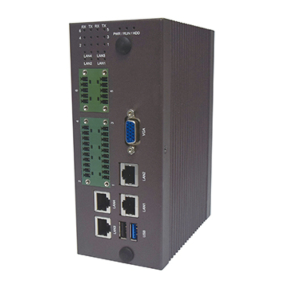
Page 19: Front I/Os
Industrial Communication Platform Front I/Os LEC-3031-A4 RX/TX LED LED signals for Serial port RX/TX status. LAN LED LED signals for LAN status PWR/RUN/HDD LED 1 x PWR/RUN/HDD LED set for power, device and storage activity status 1 x VGA display port Terminal Block (Serial COM) 2x10-pin terminal block supports 4 x RS-232/422/485 F6 &... - Page 20 Industrial Communication Platform LEC-3031-A6 RX/TX LED LED signals for Serial port RX/TX status. LAN LED LED signals for LAN status PWR/RUN/HDD LED 1 x PWR/RUN/HDD LED set for power, device and storage activity status 1 x VGA display port Terminal Block (Serial COM) 2x10-pin + 2x5-pin terminal block supports 6 x RS-232/422/485 F6 &...
- Page 21 Industrial Communication Platform LEC-3031-A8 RX/TX LED LED signals for Serial port RX/TX status LAN LED LED signals for LAN status PWR/RUN/HDD LED 1 x PWR/RUN/HDD LED set for power, device and storage activity status 1 x VGA display port Terminal Block (Serial COM) 2x10-pin + 2x10-pin terminal block supports 8 x RS-232/422/485 2 x GbE LAN ports...
- Page 22 Industrial Communication Platform LEC-3031-I4 RX/TX LED LED signals for Serial port RX/TX status LAN LED LED signals for LAN status PWR/RUN/HDD LED 1 x PWR/RUN/HDD LED set for power, device and storage activity status 1 x VGA display port Terminal Block (Serial COM) 2 x 6-pin terminal block supports 4 x isolated RS-485 2 x GbE LAN ports USB 3.0...
- Page 23 Industrial Communication Platform LEC-3031-I10 RX/TX LED LED signals for Serial port RX/TX status LAN LED LED signals for LAN status PWR/RUN/HDD LED 1 x PWR/RUN/HDD LED set for power, device and storage activity status 1 x VGA display port Terminal Block (Serial COM) 2 x 2 x 6-pin + 2 x 3-pin terminal block supports 8 x isolated RS-485 and 2 x isolated RS-232/485 2 x GbE LAN ports...
-
Page 24: Side I/Os
Industrial Communication Platform Side I/Os LEC-3031-A4/A6/A8/I4/I10 Power Input 12~36Vdc power input w/ 2xpin Phoenix Contact connector Rear I/Os LEC-3031-A4/A6/A8/I4/I10 DIN Rail DIN Rail mounting bracket... -
Page 25: Chapter 3: Board Layout
Industrial Communication Platform Chapter 3: Board Layout Jumpers & Connectors Locations on the Motherboard RJ1/2 VGA1 USB1 LPC1 SPIROM MPCIE1 PWR1... -
Page 26: Jumpers & Connectors Locations (Lek-Au4: Add-On Card For A4 Model)
Industrial Communication Platform Jumpers & Connectors Locations (LEK-AU4: Add-on Card for A4 model) LAN1/2... -
Page 27: Jumpers & Connectors Locations (Lek-Au6: Add-On Card For A6 Model)
Industrial Communication Platform Jumpers & Connectors Locations (LEK-AU6: Add-on Card for A6 model) LAN1/2... -
Page 28: Jumpers & Connectors Locations (Lek-Au8: Add-On Card For A8 Model)
Industrial Communication Platform Jumpers & Connectors Locations (LEK-AU8: Add-on Card for A8 model) -
Page 29: Jumpers & Connectors Locations (Add-On Card For I4 Model)
Industrial Communication Platform Jumpers & Connectors Locations (Add-on Card for I4 model) -
Page 30: Jumpers & Connectors Locations (Add-On Card For I10 Model)
Industrial Communication Platform Jumpers & Connectors Locations (Add-on Card for I10 model) -
Page 31: Jumpers And Connectors Table
Industrial Communication Platform Jumpers and Connectors Table The Motherboard Label Description Note RJ1-2 RJ1 and RJ2 are double-stacked LAN ports USB1 1 x USB 2.0 Type-A port 1 x USB 3.0 Type-A port VGA1 1 x VGA port Power input Board-to-board connector with PCIe signal. - Page 32 Industrial Communication Platform Board-to-board connector for connection with the motherboard LEK-AU8 as Add-On Card for A8 Label Description Note CN1-2 2x10-pin + 2x10-pin terminal block supports 8 x RS-232/422/485 SATA 7-pin signal connector SATA 4-pin power connector Board-to-board connector for connection with the motherboard LEK-3031-I4 as Add-On Card for I4 Label...
-
Page 33: Jumper Settings & Connector Pinout (Motherboard)
Industrial Communication Platform Jumper Settings & Connector Pinout (Motherboard) Jumper Setting PWR1: Power Button Jumper Description Power ON/OFF system NC (Default) Normal J1: Clear CMOS CLR1:RTC reset Jumper Description 1-2 (Default) Normal Clear CMOS Connector Pin Assignment VGA1: VGA Connector Part reference: VGA1 VGA1 Description... - Page 34 Industrial Communication Platform VGA power Ground DDC-DATA H-Sync. V-Sync. DDC-CLK RJ1 & RJ2 :Ethernet Connector Part reference: RJ1~RJ2 Pin signal In/Out MD0+ MD0- MD1+ MD1- MD2+ MD2- MD3+ MD3- USB1: USB1 Connector USB2.0 USB3.0 USB1 Description Description USB power USB power USB1N USB0N...
- Page 35 Industrial Communication Platform USB1P USB0P USB3.0_RXN USB3.0_RXP USB3.0_TXN USB3.0_TXP MPCIE1: mSATA Mini Connector (Half Size) Description Description RSVD VCC3 RSVD RSVD RSVD RSVD RSVD RSVD RSVD RSVD RSVD RSVD RSVD RSVD RSVD RSVD RSVD SATA RX+ VCC3 SATA RX- RSVD RSVD SATA TX- RSVD...
- Page 36 Industrial Communication Platform RSVD RSVD RSVD RSVD RSVD RSVD RSVD VCC3 CN2: POWER INPUT connector Description POWER SPIROM1: SPI ROM Connector (For RD debug) SPIROM1 Description Description SPI_HOLD_N SPI_CS1_R_N SPI_CS0_R_N V_3P3_SPI_R SPI_MISO_R SPI_HD0_N SPI_CLK SPI_MOSI_R LPC1: LPC Connector (For RD debug) LPC1 Pin No.
- Page 37 Industrial Communication Platform LPC_FRAME_N P3V3 LPC_AD3 LPC_AD2 J3:Board to Board Connector 2x50P Description Description Description Description LAN2_L1000_N_R COM4_RXD LAN2_ACTLED_N SW3_PCIE_TX_D COM4_TXD SWLAN_PCIE_TX_ LAN1_L100_N_R SW3_PCIE_TX_DP COM4_RTS# SWLAN_PCIE_TX_ LAN1_L1000_N_R COM4_CTS# LAN1_ACTLED_N SW3_PCIE_RX_D COM3_RXD SWLAN_PCIE_RX_ LAN1_L100_N_R SW3_PCIE_RX_DP COM3_TXD SWLAN_PCIE_RX_ SMB_SOC_CLK_3P3 COM3_RTS# SMB_SOC_DATA_3P CLK_SWCOM_PCI COM3_CTS# CLK_100M_PCIE2_ E_DN...
-
Page 38: Jumper Settings & Connector Pinout (Lek-Au4)
Industrial Communication Platform USB_P1_DN P3V3 SATA_TX1_DN USB_P1_DP SATA_TX1_DP USB_P0_DN SATA_RX1_DN PE_RST_OUT_82 USB_P0_DP SATA_RX1_DP CLK_SW3_PCIE_DN P12V CLK_SWLAN_PC IE_DN CLK_SW3_PCIE_DP P12V CLK_SWLAN_PC IE_DP Jumper Settings & Connector Pinout (LEK-AU4) Ethernet interface Part reference: LAN1~LAN2 Pin signal In/Out MD3- MD3+ MD2- MD2+ MD1- MD1+ MD0- MD0+... - Page 39 Industrial Communication Platform SATA interface Part reference: J1 Pin signal In/Out Ground Ground Ground SATA Power Connector Part reference: J2 PWR1~2 Pin signal In/Out VCC12 (12V) Ground Ground VCC (5V) COM port connector Part reference: CN1 PIN1 PIN10 PIN20...
-
Page 40: Jumper Settings & Connector Pinout (Lek-Au6)
Industrial Communication Platform RS-232 SOUT GND SIN SOUT GND RS-422 TX+ RS-485 TX+ RS-485 RS-232 SOUT GND SIN SOUT GND RS-422 TX+ RS-485 TX+ RS-485 Jumper Settings & Connector Pinout (LEK-AU6) Ethernet interface Part reference: LAN1~LAN2 Pin signal In/Out MD3- MD3+ MD2- MD2+... - Page 41 Industrial Communication Platform Ground Ground SATA Power Connector Part reference: J2 PWR1~2 Pin signal In/Out VCC12 (12V) Ground Ground VCC (5V) COM port connector Part reference: CN1 PIN1 PIN10 PIN20 RS-232 SOUT GND SIN SOUT GND RS-422 TX+ RS-485 TX+ RS-485...
- Page 42 Industrial Communication Platform RS-232 SOUT GND SIN SOUT GND RS-422 TX+ RS-485 TX+ RS-485 CN2: Connector 10Pin Description Description COM6_C_DP_TP COM5_C_DP_TP COM6_C_DN_TN COM5_C_DN_TN COM6_C_RXD_RN COM5_C_RXD_RN COM6_C_TXD_RP COM5_C_TXD_RP J3:RS-485 Enable Description 1-2 (Default) RS485 Enable...
-
Page 43: Jumper Settings & Connector Pinout (Lek-Au8)
Industrial Communication Platform Jumper Settings & Connector Pinout (LEK-AU8) SATA interface Part reference: J1 Pin signal In/Out Ground Ground Ground SATA Power Connector Part reference: J2 PWR1~2 Pin number Pin signal In/Out VCC12 (12V) Ground Ground VCC (5V) - Page 44 Industrial Communication Platform COM port connector Part reference: CN1,CN2 PIN1 PIN10 PIN20 RS-232 SOUT GND SIN SOUT GND RS-422 TX+ RS-485 TX+ RS-485 RS-232 SOUT GND SIN SOUT GND RS-422 TX+ RS-485 TX+ RS-485 J3:RS485 Enable Description 1-2 (Default) RS485 Enable...
-
Page 45: Jumper Settings & Connector Pinout (For I4)
Industrial Communication Platform Jumper Settings & Connector Pinout (for I4) SATA Power Connector Part reference: J1 PWR1~2 Pin number Pin signal In/Out VCC12 (12V) Ground Ground VCC (5V) SATA interface Part reference: J2 Pin signal In/Out Ground Ground Ground... - Page 46 Industrial Communication Platform CN4: USB1/2 Connectors Description Description VCCUSB VCCUSB01 USB1N USB0N USB1P USB0P CN2: COM3/4/5/6 RS-485 Connectors Description Description COM4_D+ COM3_D+ COM4_D- COM3_D- COM6_D+ COM5_D+ COM6_D- COM5_D-...
-
Page 47: Jumper Settings & Connector Pinout (For I10)
Industrial Communication Platform Jumper Settings & Connector Pinout (for I10) SATA Power Connector Part reference: J1 PWR1~2 Pin number Pin signal In/Out VCC12 (12V) Ground Ground VCC (5V) SATA interface Part reference: J2 Pin signal In/Out Ground Ground Ground... - Page 48 Industrial Communication Platform CN4: USB1/2 Connectors Description Description VCCUSB VCCUSB01 USB1N USB0N USB1P USB0P CN1: COM1/2 RS-232/485 Connectors RS-232 COM2_TX COM2_RX COM1_TX COM1_RX RS-485 COM2_D+ COM2_D- COM1_D+ COM1_D- CN2: COM3/4/5/6 RS-485 Connectors...
- Page 49 Industrial Communication Platform Description Description COM4_D+ COM3_D+ COM4_D- COM3_D- COM6_D+ COM5_D+ COM6_D- COM5_D- CN3: COM7/8/9/10 RS-485 Connectors Description Description COM8_D+ COM7_D+ COM8_D- COM7_D- COM10_D+ COM9_D+ COM10_D- COM9_D-...
-
Page 50: Chapter 4: Hardware Setup
Please wear ESD protected gloves before conducting the following steps. Do NOT pile items on top of the system to prevent damages due to this improper use. Lanner is not liable for damages caused by improper use of the product. - Page 51 Industrial Communication Platform 3. Open the bottom and the side compartments as shown below.
-
Page 52: Installing So-Dimm Memory
Industrial Communication Platform Installing SO-DIMM Memory The system is designed with a SO-DIMM socket supporting up to 4GB DDR3L SDRAM. Please follow the steps below for proper installations. 1. Locate the SO-DIMM socket on the motherboard. 2. Remove the heat sink by removing the two screws circled in the image below. 2. -
Page 53: Installing A Msata Mini Module
Industrial Communication Platform 5. Place the heat sink back on and apply two screws. Installing a mSATA Mini Module The system provides a mSATA mini slot for storage expansion. Please follow the steps below for installations. 1. Locate the mSATA Mini socket. 2. -
Page 54: Installing A Disk Drive
Industrial Communication Platform 4. Secure the installed module with a screw. Installing a Disk Drive The system can accommodate one 2.5” SATA disk drive. Please follow the steps below. 1. Locate the SATA drive tray on the inner side of the bottom compartment. 2. - Page 55 Industrial Communication Platform 4. Connect the supplied SATA cable to the disk drive as shown in the image below. 5. Connect the 7-pin signal connector and the 4-pin power connector to the corresponding ports on the motherboard.
-
Page 56: Mounting Lec-3031 By Din Rail
Industrial Communication Platform Mounting LEC-3031 by DIN Rail All models of the LEC-3031 series are designed with a DIN Rail mounting bracket at the rear of the product. Hang the device onto a rail until it firmly attaches. -
Page 57: Appendix 1: Watchdog Timer
Industrial Communication Platform Appendix 1: Watchdog Timer A watchdog timer is a piece of hardware that can be used to automatically detect system anomalies and reset the processor in case there are any problems. Generally speaking, a watchdog timer is based on a counter that counts down from an initial value to zero. The software selects the counter’s initial value and periodically restarts it.
Need help?
Do you have a question about the LEC-3031 Series and is the answer not in the manual?
Questions and answers