
Subscribe to Our Youtube Channel
Related Manuals for Lanner LEC-6041B


Summary of Contents for Lanner LEC-6041B
- Page 1 LEC-6041 User Manual Industrial Communication Platforms LEC-6041 User Manual Version: 1.1 Date of Release:2019-07-10...
-
Page 2: Chapter 1: Product Overview
- assumed to be qualified in the servicing of computer equipment, such as professional system integrators, or service personnel and technicians. The latest version of this document can be found on Lanner’s official website, available either through the product page or through the Lanner Download Center page with a login account and password. - Page 3 A toll-free phone support is offered to our customers in the United States and Canada, it is: +1-855-852-6637 This document is copyrighted © 2019 by Lanner Electronics Inc. All rights are reserved. The original manufacturer reserves the right to make improvements to the products described in this manual at any time without notice.
- Page 4 Chapter 1: Product Overview Taiwan Corporate Headquarters China Lanner Electronics Inc. Beijing L&S Lancom Platform Tech. Co., Ltd. 7F, No.173, Sec.2, Datong Rd. Xizhi District, Guodong LOFT 9 Layer No. 9 Huinan Road, New Taipei City 22184, Taiwan Huilongguan Town, Changping District, Beijing...
- Page 5 LEC-6041 User Manual This equipment has been tested and found to comply with the limits for a Class A digital device, pursuant to Part 15 of FCC Rules. These limits are designed to provide reasonable protection against harmful interference in a residential installation. This equipment generates, uses and can radiate radio frequency energy and, if not installed and used in accordance with the instruction, may cause harmful interference to radio communications.
- Page 6 Chapter 1: Product Overview Follow these guidelines to ensure general safety: Keep the chassis area clear and dust-free during and after installation. Do not wear loose clothing or jewelry that could get caught in the chassis. Fasten your tie or scarf and roll up your sleeves.
- Page 7 LEC-6041 User Manual Disposal of a battery into fire or a hot oven, or mechanically crushing or cutting of a battery can result in an explosion. Leaving a battery in an extremely high temperature surrounding environment can result in an explosion or the leakage of flammable liquid or gas.
- Page 8 The installation of this product must be performed by trained specialists; otherwise, a non-specialist might create the risk of the system’s falling to the ground or other damages. Lanner Electronics Inc. shall not be held liable for any losses resulting from insufficient strength for supporting the system or use of inappropriate installation components.
- Page 9 LEC-6041 User Manual Before turning on the device, ground the grounding cable of the equipment. Proper grounding (grounding) is very important to protect the equipment against the harmful effects of external noise and to reduce the risk of electrocution in the event of a lightning strike. To uninstall the equipment, disconnect the ground wire after turning off the power.
- Page 10 Chapter 1: Product Overview This equipment must be grounded. The power cord for the product should be connected to a socket-outlet with earthing connection. Cet équipement doit être mis à la terre. La fiche d'alimentation doit être connectée à une prise de terre correctement câblée Suitable for installation in Information Technology Rooms in accordance with Article 645 of the National Electrical Code and NFPA 75.
- Page 11 Installing Key Components ......................24 Installing the Hard Disk ....................... 26 Wall-Mounting the System ......................28 Rack-Mounting the System ......................29 Lanner SDK ..........................30 BIOS Setup ..........................31 Warranty Policy .......................... 72 RMA Service ..........................72 RMA Service Request Form ......................73...
- Page 12 Chapter 1: Product Overview Lanner’s LEC-6041, being the successor of LEC-6021, is designed to protect the communication in both IT and OT domains. LEC-6041 Series is empowered by Intel Atom x7-E3950 or x5-E3930 for low power consumption and high processing performance. As a rugged firewall deployed in challenging environments, LEC-6041 comes with IEC 61850-3 and IEEE 1613 certification, as well as 1.5 KV magnetic isolation...
- Page 13 LEC-6041 User Manual Intel Atom x7-E3950 or x5-E3930 Frequency Atom x5-E3930: 1.3 GHz, Atom x7-E3950: 1.6 GHz Processor System Core Number Atom x5-E3930: 2, Atom x7-E3950: 4 BIOS AMI SPI Flash BIOS Chipset Fanless Technology DDR3L, up to 1866 MHz System Memory Max.
- Page 14 Chapter 1: Product Overview Description HDMI 1x HDMI port SFP Port 2x 1G SFP port RJ45 5x RJ45 port (LAN1 & LAN2 with LAN Bypass support) USB Port 2x USB 3.0 port HDD: Hard disk activity STA: System status PWR: system power L1~L5: LAN ports activity LED Indicators F1~F2: Fiber ports activity...
- Page 15 LEC-6041 User Manual Description DIN Rail Bracket Reset Button For software reset...
- Page 16 Chapter 1: Product Overview The block diagram indicates how data flows among components on the motherboard. Please refer to the following figure for your motherboard’s layout design.
- Page 17 LEC-6041 User Manual The motherboard layout shows the connectors and jumpers on the board. Refer to the following picture as a reference of the pin assignments and the internal connectors.
- Page 18 Chapter 1: Product Overview PWR3: Power Button Jumper Description Power ON/OFF system NC (Default) Normal RST3: HW/SW Reset Selection Jumper Description Software reset 2-3 (Default) Hardware reset JCMOS1/2: Clear CMOS Jumper Description 1-2 (Default) Normal Clear CMOS...
- Page 19 LEC-6041 User Manual COM1: Serial Port 1 Connector Pin No. Description Pin No. Description COM1_R_RXD COM1_R_TXD COM1_2_GND COM2: Serial Port 2 Connector Pin No. Description Pin No. Description COM2_R_RXD COM2_R_TXD COM1_2_GND JSPI1: SPI ROM Connector (For RD debug) Pin No. Description Pin No.
- Page 20 Chapter 1: Product Overview SATAPWR1: SATA Power Connector Pin No. Description V12_S V5_S SATA1: SATA Connector Pin No. Description Pin No. Description SATA_RXN1_C SATA_TXP1_C SATA_RXP1_C SATA_TXN1_C MSATA1: MSATA Connector Pin No. Description Pin No. Description V3P3_S Mechanical Key SATA_RXP0_C V3P3_S SATA_RXN0_C SATA_TXN0_C SATA_TXP0_C...
- Page 21 LEC-6041 User Manual MPCIE1: MPCIE Connector Pin No. Description Pin No. Description WAKE# V3P3_S V1P5_S CLKREQ# UIM_PWR UIM_DATA CLK_MPCIE_DN UIM_CLK CLK_MPCIE_DP UIM_RESET Mechanical Key W_DISABLE# PERST# MPCIE_RXN V3P3_S MPCIE_RXP V1P5_S MPCIE_TXN MPCIE_TXP USB2_DN4 USB2_DP4 V3P3_S V3P3_S LED_WWAN# LED_WLAN# V1P5_S V3P3_S...
- Page 22 Chapter 1: Product Overview SIM1: SIM Card Socket Pin No. Description Pin No. Description UIM_PWR UIM_RST# UIM_CLK UIM_DATA Input Power connector: Dual power input Pin No. Description DC2+ DC2- ALARM1 ALARM2 DC1+ DC1- Note The failure of either power (DC1 or DC2) will cause both Alarm1 and Alarm2 to short-circuit.
- Page 23 LEC-6041 User Manual Connect the device to a 20~54 VDC power source. The power source comes from the AC/DC Adapter through a Phoenix contact. This power socket is specially designed to guard against a fault in power contact, i.e., the reverse of the electrical polarity will not damage the system. 1x Phoenix Contact Terminal Block Note...
-
Page 24: Chapter 2: Hardware Installation
Chapter 2: Hardware Installation 1. To install the key components including the SIM card, the mPCIe module, mSATA module and DDR2, loosen the screws indicated below so that the chassis cover can be removed. 2. With some pressure, slide the cover away from the system as shown in the picture. - Page 25 Please note, it is recommended to purchase the mSATA module and the mPCIe module from Lanner, for the thermal pads that come with the package were specifically chosen to fit into the gap between the selected modules and the heat sink.
- Page 26 Chapter 2: Hardware Installation 1. Remove the empty Disk Tray which can accommodate a 2.5” disk from the chassis cover by loosening the three screws on it. 2. Install the disk onto the tray using four provided disk screws, and then fix the tray onto the chassis cover.
- Page 27 LEC-6041 User Manual 3. Insert the other end of the SATA data cable to SATA1 port on the motherboard, and the end of the SATA power cable to SATAPWR1 port. Arrange the cables and route them neatly to avoid them from getting tangled.
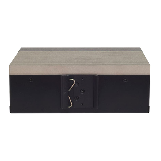
- Page 28 Chapter 2: Hardware Installation The system can be mounted to a wall with a DIN Rail Bracket. 1. Attach the Bracket to the rear of the system with 3 screws. 2. Hang the system onto a rail by engaging the hook of the Bracket into the DIN Rail until it is totally fixed.
- Page 29 LEC-6041 User Manual With the short ear brackets provided in the Ear Bracket Accessory Pack, the system can be mounted onto a desktop rack stand, or an adjustable rack the width of which can fit this system. 2x Ear Bracket 4x Ear Bracket Screw 1.
-
Page 30: Chapter 3 Software Setup
To meet today's security requirements, Lanner SDK derives unique platform identity design and integrates TPM software stack 2.0 on optional base. By leveraging Lanner SDK, the application development can be shortened, and time-to-market can be easily met, download the SDK package and instruction guide from... - Page 31 LEC-6041 User Manual BIOS is a firmware embedded on an exclusive chip on the system’ s motherboard. Lanner's BIOS firmware offering including market-proven technologies such as Secure Boot and Intel Boot Guard technology deliver solid commitments for the shield protection against malware, uncertified sequences and other named cyber threats.
- Page 32 Chapter 3 Software Setup Setup main page contains BIOS information and project version information. Feature Description BIOS Vendor : American Megatrends Core Version : AMI Kernel version, CRB code base, X64 Compliancy : UEFI version, PI version BIOS Information Project Version : BIOS release version Build Date and Time : MM/DD/YYYY Access Level: Administrator / User To set the Date, use <Tab>...
- Page 33 LEC-6041 User Manual Select the Advanced menu item from the BIOS setup screen to enter the “Advanced” setup screen. Users can select any of the items in the left frame of the screen.
-
Page 34: Trusted Computing
Chapter 3 Software Setup Trusted Computing Feature Options Description Enables or disables BIOS support for security device. Security Device Enabled By disabling this function, OS will not show Security Support Disabled Device. TCG EFI protocol and INT1A interface will not be available. -
Page 35: Operation
LEC-6041 User Manual Trusted Computing (TPM1.2) Feature Options Description Enables or disables BIOS support for security device. Security Device Enabled By disabling this function, OS will not show Security Support Disabled Device. TCG EFI protocol and INT1A interface will not be available. - Page 36 Chapter 3 Software Setup Trusted Computing (TPM2.0) Feature Options Description...
- Page 37 LEC-6041 User Manual Enables or disables BIOS support for security device. Security Device Enabled By disabling this function, OS will not show Security Support Disabled Device. TCG EFI protocol and INT1A interface will not be available. Enabled SHA-1 PCR Bank Enables or disables SHA-1 PCR Bank.
-
Page 38: Super Io Configuration
Chapter 3 Software Setup Super IO Configuration... - Page 39 LEC-6041 User Manual Serial port 1 Configuration Feature Options Description Enabled Serial Port Enables or disables Serial Port 1. Disabled Device Settings IO=3F8h; IRQ = 4 COM1 MODE RS232 Select Com Mode as RS232 Serial Port 1 (CPOM0)
- Page 40 Chapter 3 Software Setup Serial port 2 Configuration Feature Options Description Enabled Serial Port Enables or disables Serial Port 2 Disabled Device Settings IO=2F8h; IRQ = 3 COM2 MODE RS232 Select Com Mode as RS232 Serial Port2 (CPOM1)
-
Page 41: Hardware Monitor
LEC-6041 User Manual Hardware Monitor Feature Description CPU Temp This value reports the CPU temperature. SYS Temp This value reports the System temperature. CPU VCORE This value reports the CPU VCORE. VSB5V This value reports the VSB5V Input voltage. VBAT This value reports the VBAT Input voltage. -
Page 42: Watchdog Timer Configuration
Chapter 3 Software Setup Watch Dog Timer Configuration Feature Options Description Watch Dog Enabled Enables or disables Watch Dog Timer function Timer Disabled... -
Page 43: Serial Port Console Redirection
LEC-6041 User Manual Serial Port Console Redirection Feature Options Description COM0 Enabled Console Enables or disables Console Redirection Disabled Redirection... - Page 44 Chapter 3 Software Setup Console Redirection Settings Feature Options Description VT100: ASCII char set VT100 VT100+:Extends VT100 to support color, function VT100+ keys, etc. Terminal Type VT-UTF8 VT-UTF8:Uses UTF8 encoding to map Unicode ANSI chars onto 1 or more bytes ANSI: Extended ASCII char set 9600 19200...
- Page 45 LEC-6041 User Manual Hardware overflow. RTS/CTS VT-UTF8 Combo Key Disabled Enables VT-UTF8 Combination Key Support for Support Enabled ANSI/VT100 terminals Disabled With this mode enabled, only text will be sent. This Recorder Mode Enabled is to capture Terminal data. Disabled Resolution 100x31 Enables or disables extended terminal resolution Enabled...
-
Page 46: Legacy Console Redirection Settings
Chapter 3 Software Setup Legacy Console Redirection Settings Feature Options Description Legacy Serial Select a COM port to display redirection of Legacy OS COM0 Redirection Port and Legacy OPROM Messages Legacy Serial Redirection Port... -
Page 47: Cpu Configuration
LEC-6041 User Manual CPU Configuration Feature Options Description When enabled, a VMM can utilize the additional Intel Virtualization Disabled hardware capabilities provided by Vanderpool Technology Enabled Technology Disabled VT-d Enable/Disable CPU VT-d Enabled When a processor thermal sensor trips (either Bi-directional Disabled core), the PROCHOT# will be driven. - Page 48 Chapter 3 Software Setup Socket 0 CPU Information...
- Page 49 LEC-6041 User Manual CPU Power Management Feature Options Description Disabled EIST Enable/Disable Intel SpeedStep Enabled...
-
Page 50: Pci Subsystem Settings
Chapter 3 Software Setup PCI Subsystem Settings Feature Options Description Globally Enables Disables 64bit Disabled capable Devices to be Decoded in Above Above 4G Decoding Enabled 4G Address Space (Only if System Supports 64 bit PCI Decoding). Globally Enables or Disables Hot-Plug support for the entire System. -
Page 51: Csm Configuration
LEC-6041 User Manual CSM Configuration Feature Options Description Disabled CSM Support Enables or disables CSM Support Enabled Do Not Launch Controls the execution of UEFI and Network UEFI Legacy PXE OpROM Legacy Do Not Launch Controls the execution of UEFI and Storage UEFI Legacy Storage OpROM... -
Page 52: Usb Configuration
Chapter 3 Software Setup USB Configuration Feature Options Description Enables Legacy USB support. Enabled Auto option disables legacy support if Legacy USB Support Disabled no USB devices are connected; Auto Disabled option will keep USB devices available only for EFI applications. This is a workaround for OSes without Enabled XHCI... - Page 53 LEC-6041 User Manual Maximum time the device will take before it properly reports itself to the Auto Host Controller. Auto uses default value: Device power-up delay Manual for a Root port, it is 100 ms, for a Hub port the delay is taken from Hub descriptor.
- Page 54 Chapter 3 Software Setup USB Configuration Feature Options Description Disabled Control Legacy PXE Boot from Control Legacy PXE Boot from LAN1 which LAN LAN2...
- Page 55 LEC-6041 User Manual Select the Chipset menu item from the BIOS setup screen to enter the Platform Setup screen. Users can select any of the items in the left frame of the screen.
-
Page 56: North Bridge
Chapter 3 Software Setup North Bridge Feature Options Description 2 GB 2.25 GB Max TOLUD 2.5 GB Maximum Value of TOLUD. 2.75 GB 3 GB Enable/Disable above Above 4GB MMIO Enabled MemoryMappedIO BIOS assignment BIOS assignment Disabled This is disabled automatically when Aperture Size is set to 2048MB... -
Page 57: South Bridge
LEC-6041 User Manual South Bridge Feature Options Description Quiet Serial IRQ Mode Configure Serial IRQ Mode. Continuous Windows Android OS Selection Select the target OS Win7 Intel Linux... - Page 58 Chapter 3 Software Setup South Cluster Configuration...
- Page 59 LEC-6041 User Manual SATA Drives Please refer to Connector Pin Assignment for the physical port location: SATA Port0 = mSATA storage SATA Port1 = SATA1 port (on motherboard)
- Page 60 Chapter 3 Software Setup Feature Options Description Aggressive LPM Enabled Enable PCH to aggressively enter link Support Disabled power state. Enabled Port 0 Enable or Disable SATA Port Disabled SATA Port 0 Hot Plug Enabled If enabled, SATA port will be reported as Capability Disabled Hot Plug capable.
- Page 61 LEC-6041 User Manual USB Configuration Feature Options Description Once disabled, XHCI controller would be function disabled, none of the USB Enable xHCI Mode devices are detectable and usable during Disable boot and in OS. Do not disable it unless for debug purpose.
- Page 62 Chapter 3 Software Setup Miscellaneous Configuration Feature Options Description Specify what state to go to when power is re-applied after a power failure (G3 Power On state).S0 State: System will boot directly Restore AC Power Loss Power Off as soon as power applied.S5 State: Last State System keeps in power-off state until power button is pressed.
- Page 63 LEC-6041 User Manual Select the Security menu item from the BIOS setup screen to enter the Security Setup screen. Users can select any of the items in the left frame of the screen. Feature Description If ONLY the Administrator's password is set, it only limits access to Setup and is only asked for when Setup Administrator Password entering Setup.
-
Page 64: Secure Boot
Chapter 3 Software Setup Secure Boot Feature Options Description Secure Boot is activated when Platform Key(PK) is Attempt Secure Disabled enrolled, System mode is User/Deployed, and CSM Boot Enabled function is disabled. Secure Boot mode selector: Standard Secure Boot Mode In Custom mode, Secure Boot Variables can be Custom configured without authentication... - Page 65 LEC-6041 User Manual Key Management Feature Options Description Provision Factory Disabled Allows User to provision factory default Secure Default keys Enabled Boot keys when System is in Setup Mode. Install Factory Forces System to User Mode - install all Factory None Default keys Default keys...
- Page 66 Chapter 3 Software Setup Select the Boot menu item from the BIOS setup screen to enter the Boot Setup screen. Users can select any of the items in the left frame of the screen. Feature Options Description The Number of seconds to wait for setup Setup Prompt Timeout activation key.
- Page 67 Chapter 3 Software Setup Select the Save & Exit menu item from the BIOS setup screen to enter the Save and Exit Setup screen. Users can select any of the items in the left frame of the screen. Discard Changes and Exit Select this option to quit Setup without saving any modifications to the system configuration.
- Page 68 LEC-6041 User Manual Restore Defaults Restore default values for all setup options. Select “Yes” to load Optimized defaults. Note: The items under Boot Override were not same with image. It should depend on devices connect to this system.
-
Page 69: Appendix A: Led Indicator Explanations
Appendix A: LED Indicator Explanations HDD Activity If this LED blinks, it indicates data access activities; otherwise, it remains off. Data access activity No data access activity System Status This LED indicator is programmable. You could program it to display the operating status of the behaviors described below: Solid Green Defined by GPIO... - Page 70 LEC-6041 User Manual F1-F2 Fiber Port There is fiber activity on this port Fiber link status No link is established C1-C2 COM Port TX Activity Data transmitting No data activity RX Activity Data receiving No data activity...
-
Page 71: Appendix B: Setting Up Console Redirections
Appendix B: Setting up Console Redirections Console redirection lets you monitor and configure a system from a remote terminal computer by re-directing keyboard input and text output through the serial port. The following steps illustrate how to use this feature. The BIOS of the system allows the redirection of the console I/O to a serial port. With this configured, you can remotely access the entire boot sequence through a console port. - Page 72 LEC-6041 User Manual 1. All products are under warranty against defects in materials and workmanship for a period of one year from the date of purchase. 2. The buyer will bear the return freight charges for goods returned for repair within the warranty period; whereas the manufacturer will bear the after service freight charges for goods returned to the user.
-
Page 73: Appendix C: Terms And Conditions
Appendix C: Terms and Conditions When requesting RMA service, please fill out the following form. Without this form enclosed, your RMA cannot be processed.
Need help?
Do you have a question about the LEC-6041B and is the answer not in the manual?
Questions and answers