Table of Contents
Advertisement
Quick Links
Advertisement
Table of Contents

Subscribe to Our Youtube Channel
Related Manuals for Ingeteam INGECON SUN 3Play TL U M


Summary of Contents for Ingeteam INGECON SUN 3Play TL U M
- Page 1 Combiner Box INGECON SUN 3Play TL U M Installation manual Manual de instalación...
- Page 2 Tel.: +1 (414) 934 4100 Fax.: +1 (414) 342 0736 e-mail: solar.us@ingeteam.com Service Call Center: +1 (414) 934 4158 Ingeteam Power Technology, S.A. - Energy Avda. Ciudad de la Innovación, 13 31621 SARRIGUREN (Navarra) - Spain Tel.: +34 948 28 80 00 Fax.: +34 948 28 80 01...
- Page 3 Ingeteam English Español...
- Page 4 Ingeteam The copy, distribution or use of this document or of its content requires written authorisation. Any breach thereof will be reported for damages. All rights reserved including those of patent rights or design registration. The conformity of the document content with the hardware described has been checked. However, discrepancies may exist. Liability will not be assumed for total concordance.
-
Page 5: Important Safety Instructions
Category III - 1000-Volt measuring instruments must be used for checking for the absence of voltage. Ingeteam accepts no liability for any damages caused by improper use of the equipment. You must propose in advance to Ingeteam any work carried out on any equipment which implies a modification of the original electrical arrangements. -
Page 6: Personal Protective Equipment (Ppe)
Do not disconnect or connect any terminal while the inverter is operating. Disconnect and check for absence of voltage first. Personal Protective Equipment (PPE) When working on the unit, use the following safety equipment recommended by Ingeteam as a minimum. Name Explanation Safety footwear In compliance with standard ANSI Z41.1-1991... -
Page 7: Table Of Contents
Contents Ingeteam Contents Important Safety Instructions ........................5 Safety conditions ........................... 5 Personal Protective Equipment (PPE) ...................... 6 Contents ..............................7 1. About this manual ..........................8 1.1. Recipients ............................. 8 1.2. Symbols ............................8 2. Unit description ............................. 9 2.1. -
Page 8: About This Manual
Ingeteam About this manual 1. About this manual This manual describes the INGECON SUN 3Play U inverter combiner boxes and provides information for their correct reception, installation and maintenance. 1.1. Recipients This document is intended for qualified personnel. The status of qualified personnel referred to in this manual will be, as a minimum, that which meets all the standards, regulations and laws regarding safety applicable to the tasks of installing and operating this unit. -
Page 9: Unit Description
Unit description Ingeteam 2. Unit description 2.1. Overview In order to facilitate the connection and disconnection of the INGECON SUN 3Play inverter, it is possible to add a combiner box. 2.2. Electrical diagram of the system Inverter MPPT1 AFCI AFCI... -
Page 10: Replacements
Ingeteam Unit description Gauge Manufacturer Manufacturer reference Littlefuse 0SPF020.T Bussmann PV-20A10F 20 A DF Electrics 491635 Siba 50 215 28.20 Littlefuse 0SPF015.T Bussmann PV-15A10F 15 A DF Electrics 491629 Siba 50 215 28.15 Littlefuse 0SPF012.T Bussmann PV-12A10F 12 A DF Electrics 491625 Siba 50 215 28.12... -
Page 11: Receipt Of The Unit And Storage
Failure to follow the instructions in this section may lead to damage to the unit. Ingeteam accepts no liability for damage resulting from the failure to follow these instructions. If the unit is not installed immediately after reception, take into account the following points in order to avoid damage: •... -
Page 12: Preparation For Installing The Unit
Ingeteam Preparation for installing the unit 4. Preparation for installing the unit When deciding the location of the unit and planning your installation, you must follow a set of guidelines based on the specifications of the unit. These guidelines are summarized in this chapter. -
Page 13: Supporting Surface And Fastening
Preparation for installing the unit Ingeteam 4.3. Supporting Surface and Fastening The combiner box must be installed in accordance with the specifications in the following figure. The permitted positive inclination is between the range of 15 to 90º. The installation with negative inclination (example on the right) is not permitted. -
Page 14: Installing The Unit
Ingeteam Installing the unit 5. Installing the unit Before installing the unit, you must remove the packaging, taking special care not to damage the housing. Check that there is no condensation inside the packaging. If there are signs of condensation, the unit must not be installed until you are sure it is completely dry. -
Page 15: Fastening The Combiner Box Next To The Inverter
Installing the unit Ingeteam 5.3.1. Fastening the combiner box next to the inverter Use the template supplied with the combiner box to mark the holes to be made in the wall, always respecting the distances regarding the inverter anchor points. Drill the necessary holes. - Page 16 Ingeteam Installing the unit Unscrew the four side bolts and remove the two rear plates. For each of the rear plates, observe the following points. Take out the plate. ABI2014IQM03_ - Installation manual...
- Page 17 Installing the unit Ingeteam Turn the plate 180º as shown in the following figure. 180º Turn the plate 90º as shown in the following figure. 90º ABI2014IQM03_ - Installation manual...
- Page 18 Ingeteam Installing the unit Bolt the plate to the wall. The result of fastening both plates can be seen in the following figure. Fit the combiner box onto the plates. Once it is fitted, secure it by fastening the two bolts removed in point 2.
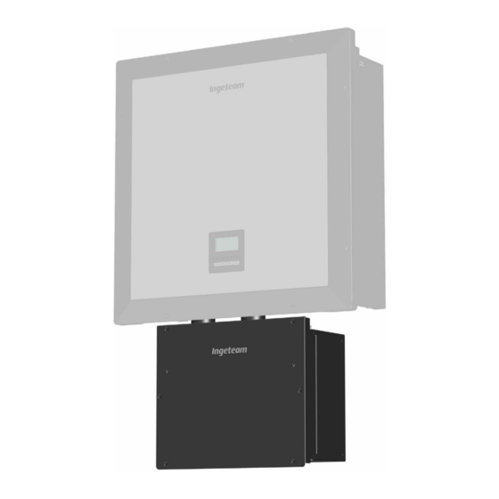
- Page 19 Installing the unit Ingeteam Install the ducts in the combiner box. To maintain the protection rating, the insulating seals supplied must be installed. Hang the inverter from its plate, inserting the combiner box ducts into the bottom holes of the inverter.
-
Page 20: Fastening The Combiner Box Separated From The Inverter
Ingeteam Installing the unit 10. Check that the installation is firm. 5.3.2. Fastening the combiner box separated from the inverter Unscrew the four side bolts and remove the two rear plates. Use the template to mark the four holes necessary to fasten the rear plates.
Need help?
Do you have a question about the INGECON SUN 3Play TL U M and is the answer not in the manual?
Questions and answers