Table of Contents
Advertisement
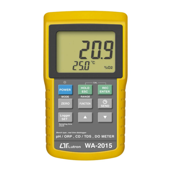
Bench type, RS232/USB computer interface
pH, ORP, CD, TDS, DO, SALT
METER
Model : WA-2015
OPERATION MANUAL
Your purchase of this
pH, ORP, CD, TDS, DO,
SALT METER with SD
CARD
DATALOGGER
marks a step forward for
you into the field of
precision measurement.
Although this METER is
a complex and delicate
instrument, its durable
structure
will
many years of use if
p r o p e r
o p e r a t i n g
t e c h n i q u e s
developed. Please read
t h e
f o l l o w i n g
instructions
and always keep this
manual
within
reach.
allow
a r e
carefully
easy
Advertisement
Table of Contents

Subscribe to Our Youtube Channel
Related Manuals for Lutron Electronics WA-2015


Summary of Contents for Lutron Electronics WA-2015
- Page 1 Bench type, RS232/USB computer interface pH, ORP, CD, TDS, DO, SALT METER Model : WA-2015 Your purchase of this pH, ORP, CD, TDS, DO, SALT METER with SD CARD DATALOGGER marks a step forward for you into the field of precision measurement.
-
Page 2: Table Of Contents
TABLE OF CONTENTS 1. FEATURES..............1 2. SPECIFICATIONS............3 2-1 General Specifications..........3 2-2 Electrical Specifications........5 3. FRONT PANEL DESCRIPTION........9 4. MODE SELECTION ( pH/CD/DO selection )....11 5. pH/mV MEASURING and CALIBRATION PROCEDURE.............12 6. CONDUCTIVITY/TDS MEASURING and CALIBRATION PROCEDURE........19 7. DO (Dissolved Oxygen) MEASURING and CALIBRATION PROCEDURE.........24 8. -
Page 3: Features
1. FEATURES * Professional bench type meter with large size LCD display with green color back light. * One meter for multi purpose operation : pH/ORP, CD/TDS ( Total dissolved solids ), Dissolved Oxygen. * pH : 0 to 14.00 pH, ORP : ± 1999 mV. * Conductivity : 200 uS/2 mS/20 mS/200 mS. - Page 4 * Dissolved oxygen meter use the polar graphic type oxygen probe with temperature sensor, high precision measurement for Dissolved Oxygen ( DO ) and temperature measurement. * Heavy duty dissolved oxygen probe, probe head can connect with BOD bottle. * DO use the automatic Temp. compensation. * DO meter build in "...
-
Page 5: Specifications
2. SPECIFICATIONS 2-1 General Specifications Circuit Custom one-chip of microprocessor LSI circuit. Display LCD size : 82 mm x 61 mm. * with green color backlight. Measurement pH/ORP Conductivity/TDS(Total Dissolved Solids) Dissolved Oxygen Auto data logger : Sampling Time of Data Logger 1 sec to 8 hour 59 min. 59 sec. Manual data logger : Set sampling time to 0 second. - Page 6 Power Operation ( LCD backlight ON ) : Consumption Approx. DC 32 mA Operation ( LCD backlight OFF ) : Approx. DC 8 mA Power OFF ( only internal clock running ) : Approx. DC 1.8 uA. Weight 1049 g/2.3 LB. * meter Dimension 225 X 125 X 64 mm...
-
Page 7: Electrical Specifications
2-2 Electrical Specifications (23± 5 ℃ A. pH/mV Optional, Electrode Any pH electrode with BNC connector. Measurement 0 to 14 pH -1999 mV to 1999 mV Input 10^12 ohm Impedance Temperature Manual 0 to 100 , be adjusted by ℃ Compensation push button on front panel. - Page 8 B. Conductivity Conductivity Optional, probe Carbon rod electrode for long life. Function * Conductivity ( uS, mS ) * TDS ( Total Dissolved Solids, PPM ) * Temperature ( ℃ ℉ Temperature Automatic from 0 to 60 (32 - 140 ℃...
- Page 9 2. TDS ( Total Dissolved Solids ) Range Measurement Resolution Accuracy 200 PPM 0 to 132 PPM 0.1 PPM 2,000 PPM 132 to 1,320 PPM 1 PPM ± (2% F.S.+1d) 20,000 PPM 1,320 to 13,200 PPM 10 PPM * F.S. - Full scale 200,000 PPM 13,200 to 132,000 PPM 100 PPM * Temperature Compensation :...
- Page 10 Accuracy Dissolved Oxygen ± 0.4 mg/L. (23± 5 Oxygen in Air ± 0.7% O2. ℃ Temperature ± 0.8 /1.5 ℃ ℉ Probe Temperature 0 to 50 ℃ Compensation Automatic & Adj. Salt 0 to 50 % Salt Height ( M. T.) 0 to 8900 meter Probe Weight 335 g/0.74 LB ( batteries &...
-
Page 11: Front Panel Description
3. FRONT PANEL DESCRIPTION Fig. 1-1... - Page 12 Fig. 1-2 3-1 Display 3-2 Power Button ( LCD Backlight Button ) 3-3 HOLD Button ( ESC Button ) 3-4 REC Button ( Enter Button ) 3-5 Mode Button ( Zero Button ) 3-6 Function Button ( Range Button ) 3-7 Send Button ( Clock Button ) 3-8 SET Button ( Logger Button ) Up Button...
-
Page 13: Mode Selection ( Ph/Cd/Do Selection )
4. MODE SELECTION ( pH/CD/DO selection ) 1) Turn on the meter by pressing the " Power Button " ( 3-2, Fig. 1 ) momentarily. Pressing the " Power Button " ( 3-2, Fig. 1 ) continuously and > 2 seconds again will turn off the meter. -
Page 14: Ph/Mv Measuring And Calibration Procedure
5. pH/mV MEASURING and CALIBRATION PROCEDURE The meter default function are following : * The display unit is set to pH. * The temperature unit is set to ℃ * Manual ATC ( without connect the ATC probe ) * Auto power off. * The sampling time of data logger function is 2 seconds. - Page 15 5-1 pH measurement ( manual Temp compensation ) 1) Prepare the pH Electrode ( optional ), install the " Probe Plug " ( 4-1, Fig. 2 ) into the " pH Socket/BNC Socket " ( 3-11, Fig. 1 ). 2) Power on the meter by pressing " Power Button " ( 3-2, Fig.
- Page 16 5-3 mV Measurement The instrument build in mV ( millivolt ) measurement function, which enable you to make ion-selective, ORP (oxidation-reduction potential), and other precise mV measurements. 1) Prepare the ORP Electrode ( optional, ORP-14 ), install the " Probe Plug " of ORP electrode into the " pH Socket/BNC Socket "...
- Page 17 Required Equipment for Calibration 1) pH ELECTRODE ( optional ). 2) pH buffer solutions ( optional ). Calibration Procedure 1) Prepare the pH Electrode ( optional ), install the " Probe Plug " ( 4-1, Fig. 2 ) into the " pH Socket/BNC Socket "...
- Page 18 5) Use the two fingers to press the " REC Button " ( 3-4, Fig 1 ) and " HOLD Button " ( 3-3, Fig. 1 ) at the same time. Until Display will show the following screen then release the both fingers. 6) Press the "...
- Page 19 When select the and press the " Enter Button " will clear the existing calibration data. 7) Fine adjustment of calibration value During the calibration when the main Display ( 7.00, 4.00 or 10.00 ) is flashed, it can use the " Button "...
- Page 20 5-5 ORP calibration 1) Prepare the ORP electrode ( optional, ORP-14 ), connect the ORP electrode to the meter. 2) Power on the meter, set the mode and the function to " mV ", refer chapter 5-3, page 14. 3) Immerse the sensing head of ORP electrode into the ORP standard buffer solution, the up display will show the ORP value in mV.
-
Page 21: Conductivity/Tds Measuring And Calibration Procedure
6. CONDUCTIVITY/TDS MEASURING and CALIBRATION PROCEDURE The meter default function are following : * The display unit is set to conductivity ( uS, mS ). * The temperature unit is set to ℃ * Temp. compensation factor is set to 2.0% per C. * Auto range. - Page 22 6-1 uS, mS measurement 1) Prepare the Conductivity Probe ( optional, CDPB-03 ), install the " Probe Plug " ( 5-1, Fig. 3 ) into the " CD Socket " ( 3-12, Fig. 1 ). 2) Power on the meter by pressing " Power Button " ( 3-2, Fig.
- Page 23 * If the display shows " ", it indicates an overload condition, select the next higher range. * If the display shows " ", it indicates an out-of-range, select the next lower range. * If intend to change the operation mode from Manual range back to Auto Range, press the "...
- Page 24 6-2 TDS ( PPM ) measurement The measuring procedures are same as above 5-1 Conductivity ( uS, mS ) measurement, except to change the display unit from uS, mS to PPM. The procedures are : * Press the " Function Button " ( 3-6, Fig. 1 ) > 2 seconds continuously until the Display show the text "...
- Page 25 5) Use the two fingers to press the " REC Button " ( 3-4, Fig 1 ) and " HOLD Button " ( 3-3, Fig. 1 ) at the same time. the display will show the following screen as example, release the both fingers. 6) Use "...
-
Page 26: Do (Dissolved Oxygen) Measuring And Calibration Procedure
7. DO (Dissolved Oxygen) MEASURING and CALIBRATION PROCEDURE 1) Prepare the Oxygen Probe ( optional, OXPB-11 ) ATTENTION : Fill the Probe's Electrolyte at first. Intend to keep the DO probe under the best condition, it should fill the Probe's Electrolyte at first. Probe-filling Electrolyte Probe head with diaphragm set The procedures that to fill the Probe's... - Page 27 The meter default function are following : * The display unit is set to mg/L. * The temperature unit is set to ℃ * Auto power off. * The sampling time of data logger function is 2 seconds. 7-1 Dissolved Oxygen measurement Fig.
- Page 28 1) Prepare the Oxygen Probe ( optional, DOPB-11 ), install the " Probe Plug " ( 6-1, Fig. 4 ) into the " DO Socket " ( 3-13, Fig. 1 ). 2) Power on the meter by pressing " Power Button " ( 3-2, Fig.
- Page 29 b. As for the thermal equilibrium to occur between the probe & the measurement sample must be allowed to pass, which usually amounts to a few minutes if the Temp. difference between the two is only several Celsius degrees. 5) a. In order to measure the dissolved oxygen content in any given liquid, it is sufficient to immerse the tip of the probe in the solution, making sure that velocity of the liquid coming into contact with the probe is at...
- Page 30 "% Salt" compensation value adjustment If intend to change the % Salt compensation value, refer page 38, chapter 9-8 ( % Salt Compensation value Setting ). "Height" compensation value adjustment If intend to change the Height compensation value, refer page 39, chapter 9-9, 9-10 ( Height Compensation value Setting ).
- Page 31 5) Press the " Enter Button " ( 3-4, Fig. 1 ), the Display value will count down from 30 to 0, then return to normal measuring screen and finish the calibration procedures. The complete calibration procedures will take 30 seconds approximately. After finish the calibration, press the "...
- Page 32 The consideration of diaphragm ( probe head with diaphragm set ) : The oxygen probe component is the thin Teflon diaphragm housed in the tip of the probe. The diaphragm is permeable by the oxygen molecules but not by the considerably larger molecules contained in the electrolyte.
-
Page 33: Data Hold, Data Record, Data Logger
4) Screw the " Probe head " ( 7-3, Fig 5 ) into the probe body. Fig. 5 When not use the probe, should insert the " Probe head " into the " Probe 7-1 Probe handle protection cover " 7-2 Temp. - Page 34 b)Press the " REC Button " ( 3-4, Fig. 1 ) again, the " REC MIN " symbol along with the minimum value will appear on the display. If intend to delete the minimum value, just press the " Hold Button " ( 3-3, Fig. 1 ) once, then the display will show the "...
- Page 35 Manual Data Logger ( Sampling time set to 0 second ) Press the " Logger Button " ( 3-8, Fig. 1 ) once will save the data one time into the memory. Beeper will sound and the upper display will show "...
-
Page 36: Advanced Adjustment Procedure
9. ADVANCED ADJUSTMENT PROCEDURES Under do not execute the Datalogger function, press the " SET Button " ( 3-8, Fig. 1 ) continuously at least two seconds will enter the " Advanced Setting " mode, press the " SET Button " ( 3-8, Fig. 1 ) once a while in sequence to select the 13 main function, the display will show : SPACE... -
Page 37: Check Memory Space
b. During execute the " Advanced Setting " function, if press " ESC Button " ( 3-3, Fig. 1 ) will exit the " Advanced Setting " function, the LCD will return to normal screen. 9-1 Check memory space When the display show " SPACE " To check the balance data numbers that exist into the memory ( allow the balance memorize data no. -
Page 38: Set Date/Time
9-3 Set Date/Time ( Year/Month/Date, Hour/Minute/ Second ) When the upper display show " dAtE " 1) Use the " Button " ( 3-9, Fig. 1 ) or " Button " ▲ ▼ ( 3-10, Fig. 1 ) to adjust the value ( Setting start from Year value ). -
Page 39: Auto Power Off Management
Remark : The adjusted value will be flashed. 2) After set all the sampling time value ( Hour, Minute, Second ), press the " SET Button " ( 3-8, Fig. 1 ) once will save the sampling value with default then the screen will jump to "... -
Page 40: Set Ph Manual Temp. Compensation Value
2) After Display unit is selected to " C " or " F ", press the " Enter Button " ( 3-4, Fig. 1 ) will save the setting function with default. 9-7 Set pH manual Temp. compensation value When the lower display show " t-SEt " 1) This function only for the pH measurement of adjusting the pH electrode's manual Temp.compensation value. -
Page 41: Set Do Height ( Meter ) Compensation Value
9-9 Set DO height ( meter ) compensation value When the lower display show " High- " 1) This function only for the DO ( Disolved oxygen ) mode of adjusting the probe's height compensation value in meter unit. The default value is 0 meter. 2) Use the "... -
Page 42: Set Cd Temperature Compensation Factor
9-11 Set CD temperature compensation factor When the lower display show " PEr C " 1) This function only for the Conductivity ( TDS ) mode of adjusting the probe's Temp. compensation value in %/per unit. The default value is 2 %/ per ℃... -
Page 43: Send The Data Out From The Meter
10. SEND THE DATA OUT FROM THE METER 1) If intend to send the data out from the meter, it should exit the " Hold function " and the " Record function " first. The display should be not show the "... - Page 44 Block 1 Data 1 Data X ↓ Block 2 Data X+1 Data Y ↓ ........↓ Block 250 Data Z Data 16,000 3) Until the desired Memory Block no. be selected. Push the " Send Button " ( 3-7, Fig. 1 ) once, the data in the Memory Block will send out.
-
Page 45: Rs232 Pc Serial Interface
11. RS232 PC SERIAL INTERFACE The instrument has RS232 PC serial interface via the RS-232 Out Terminal " ( 3-15, Fig. 1 ). The data output is a 16 digit stream which can be utilized for user's specific application. A RS232 lead with the following connection will be required to link the instrument with the PC serial port. - Page 46 Each digit indicates the following status : Start Word = 02 When send the upper display data = 1 When send the lower display data = 2 D12, D11 Annunciator for Display uS = 13 mS = 14 PPM = 19 pH = 05 mV = 18 mg/L = 07...
-
Page 47: Battery Replacement
12. BATTERY REPLACEMENT 1) When the left corner of LCD display show " ", it is necessary to replace the batteries ( UM3/1.5 V x 8 PCs ). 2) Slide the " Battery Cover " ( 3-19, Fig. 1 ) away from the instrument and remove the batteries. -
Page 48: Optional Accessories
14. OPTIONAL ACCESSORIES RS232 cable * Computer interface cable. UPCB-02 * Used to connect the meter to the computer ( COM port ). USB cable * Computer interface cable. USB-01 * Used to connect the meter to the computer ( USB port ). Data Logger * Software the used to download software... - Page 49 * pH Electrode, 1 to 13 pH. optional Model : PE-11 accessories * pH Electrode, 1 to 13 pH. Model : PE-03 * pH Electrode, 0 to 14 pH. Model : PE-01 * Glass body heavy duty pH Electrode, 0 to 14 pH. Model : PE-02 * Glass body plane pH Electrode, 0 to 14 pH.
Need help?
Do you have a question about the WA-2015 and is the answer not in the manual?
Questions and answers