Table of Contents
Advertisement
Quick Links
SD card real time datalogger
HUMIDITY/TEMP. MONITOR
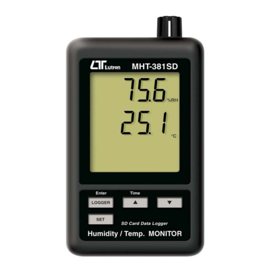
Model : MHT-381SD
OPERATION MANUAL
Your purchase of this
HUMIDITY/TEMP.
MONITOR with SD CARD
DATALOGGER marks a
step forward for you
into
the
precision measurement.
A l t h o u g h
DATALOGGER
complex
and
instrument, its durable
structure
will
many years of use if
p r o p e r
o p e r a t i n g
t e c h n i q u e s
developed. Please read
t h e
f o l l o w i n g
instructions
and always keep this
manual
within
reach.
field
of
t h i s
is
a
delicate
allow
a r e
carefully
easy
Advertisement
Table of Contents

Related Manuals for Lutron Electronics MHT-381SD


Summary of Contents for Lutron Electronics MHT-381SD
- Page 1 SD card real time datalogger HUMIDITY/TEMP. MONITOR Model : MHT-381SD Your purchase of this HUMIDITY/TEMP. MONITOR with SD CARD DATALOGGER marks a step forward for you into field precision measurement. A l t h o u g h t h i s...
- Page 2 TABLE OF CONTENTS 1. FEATURES..............1 2. SPECIFICATIONS............1 3. FRONT PANEL DESCRIPTION........4 3-1 Display..............4 3-2 Logger button, Enter button........4 button, Time button........... ▲ button............... ▼ 3-5 SET button............4 3-6 Humidity/Temp. sensor.......... 4 3-7 Hanging holes............4 3-8 Stand..............4 3-9 Battery cover/Battery compartment......4 3-10 Screw of the battery cover........4 3-11 Reset button............4...
-
Page 3: Specifications
1. FEATURES * Monitor with real time data logger, save the measuring data along the time information ( year, month, date, minute, second ) into the SD memory card and can be down load to the Excel, extra software is no need. User can make the further data or graphic analysis by themselves. - Page 4 Datalogger 5/10/30/60/120/300/600 seconds Sampling Time or Auto. Default sampling time is 60 seconds. The " Auto " sampling . means when the measuring value is changed ( > ± 1 %RH or > ± 1 ) will save the ℃ data one time only.
- Page 5 Battery life If use the new battery ( alkaline type ) and sampling time set to 60 seconds, the battery life will be > one month typically. Weight 282 g/0.62 LB. Dimension 132 x 80 x 32 mm ( 5.2 x 3.1 x 1.3 inch ) Accessories Instruction manual......
-
Page 6: Front Panel Description
3. FRONT PANEL DESCRIPTION Fig. 1 3-1 Display 3-2 Logger button, Enter button button, Time button ▲ button ▼ 3-5 SET button 3-6 Humidity/Temp. sensor 3-7 Hanging holes 3-8 Stand 3-9 Battery cover/Battery compartment 3-10 Screw of the battery cover 3-11 Reset button 3-12 RS-232 output terminal 3-13 SD card socket... -
Page 7: Measuring Procedure
4. MEASURING PROCEDURE 1) Install the batteries into the battery compartment : * Loose the " Screw of the battery cover " ( 3-10, Fig. 1 ) and take away the " Battery Cover " ( 3-9, Fig. 1 ) from the meter. - Page 8 d. Decimal format setting The numerical data structure of SD card is default used the " . " as the decimal, for example "20.6" "1000.53" . But in certain countries ( Europe ...) is used the " , " as the decimal point, for example "...
- Page 9 5-2 Datalogger a. Start the datalogger Press the " Logger button ( 3-2, Fig. 1 ) > 2 seconds continuously, until the Display show the indicator " DATALOGGER ", release the " Logger Button " ( 3-2, Fig. 1 ), then the measuring data along the time information will be saved into the memory circuit.
- Page 10 5-4 SD Card Data structure 1) When the first time, the SD card is used into the meter, the SD card will generate a folder : HTC01 2) If the first time to execute the Datalogger, under the route HTC01\, will generate a new file name HTC01001.XLS.
- Page 11 6. Saving data from the SD card to the computer ( EXCEL software ) 1) After execute the Data Logger function, take away the SD card out from the " SD card socket " ( 3-13, Fig. 1 ). 2) Plug in the SD card into the Computer's SD card slot ( if your computer build in this installation ) or insert the SD card into the "...
-
Page 12: Advanced Setting
EXCEL graphic screen ( for example ) 7. ADVANCED SETTING Under do not execute the Datalogger function, press the " SET button " ( 3-5, Fig. 1 ) > 2 seconds continuously will enter the " Setting " mode., then release the " SET button ". Following press the "... -
Page 13: Set Clock Time ( Year/Month/Date, Hour/Minute/ Second )
Remark : During execute the " Setting " function, if within 5 seconds , do not press any buttons further, the LCD Display will return to normal screen. 7-1 SD memory card Format When the Display show " Sd F " 1) Use the "... - Page 14 Remark : The adjusted unit will be flashed. 2) After set all the time value ( Year, Month, Date, Hour, Minute, Second ), press the " SET button " ( 3-5, Fig. 1 ) once will save the time value, then the screen will jump to Sampling time "...
- Page 15 yES - Meter's beep sound will be ON with default when save each data. no - Meter's beep sound will be OFF with default. when save each data. 2) After select the upper text to " yES " or " no ", press the "...
- Page 16 7-6 Select the Temp. unit to ℃ ℉ When the Display show " t-CF " 1) Use the " Button " ( 3-3, Fig. 1 ) or " Button " ▲ ▼ ( 3-4, Fig. 1 ) to select the upper Display text to " C " or "...
-
Page 17: Power Supply From Dc Adapter
8. POWER SUPPLY from DC ADAPTER The meter also can supply the power supply from the DC 9V Power Adapter ( optional ). Insert the plug of Power Adapter into " DC 9V Power Adapter Input Socket " ( 3-14, Fig. 1 ). 9. -
Page 18: Rs232 Pc Serial Interface
11. RS232 PC SERIAL INTERFACE The instrument has RS232 PC serial interface via a 3.5 mm terminal ( 3-12, Fig. 1 ) if the RS232 function already select to " ON ", refer to chapter 7-7, page 14. The data output is a 16 digit stream which can be utilized for user's specific application. -
Page 19: Patent Pending
Decimal Point(DP), position from right to the left 0 = No DP, 1= 1 DP, 2 = 2 DP, 3 = 3 DP Polarity 0 = Positive 1 = Negative D11 & D12 Annunciator for Display = 01 = 02 % RH = 04 ℃...
Need help?
Do you have a question about the MHT-381SD and is the answer not in the manual?
Questions and answers