
Related Manuals for Amprobe GROUND PROBE GP-1


Summary of Contents for Amprobe GROUND PROBE GP-1
- Page 1 AMPROBE ® GP-1 EARTH TESTER GROUND PROBE ™ User’s Manual Amprobe thanks you for purchasing the GP-1. For your safety, please read this instruction manual in its entirety. Part No. 947749 revA 7/2000...
- Page 2 SAFETY PRECAUTIONS & WARNINGS 1.Read this manual in its entirety before proceeding with any testing. 2.This equipment should only be used by trained professionals who are familiar with electrical hazards. 3. Wear lineman gloves at all times. 4.This unit has been designed and tested for user and instrument protection up to 600VAC maximum.
-
Page 3: Table Of Contents
Table of Contents Instrument Description ......... .4 Items Affecting Ground Electrode Resistance . -
Page 4: Instrument Description
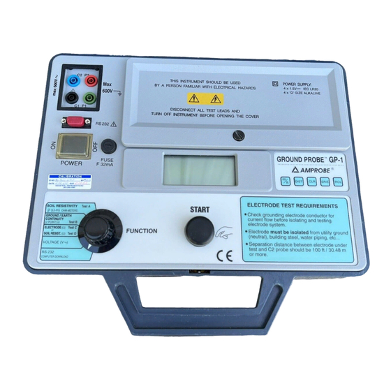
Instrument Description View of Instrument Controls Battery Cover Control Test Panel lead/cable (see next input ports page for details on control RS-232 panel) output port Power ON/OFF Fuse/Fuse Holder Function selector switch Battery Cover Liquid Crystal START button Screw Display ITEMS AFFECTING GROUND ELECTRODE RESISTANCE The soil’s ability to conduct current is dependent on the following: 1.The amount of moisture in the soil... -
Page 5: Memory Storage Control
Memory Storage Control View of Control Panel METER/ RECALL FEET CLEAR button SELECTOR button SAVE button button DISTANCE SELECTOR button SAVE all test results, excluding voltage, can be saved into memory by pressing the SAVE button. Each time the SAVE button is pressed, the next consecutive memory location is displayed and the information is saved to that location. -
Page 6: Soil Resistivity Test A (Wenner Method)
Soil Resistivity Test: Test A (Wenner Method) Test lead/cable input jacks Function selector switch 1) Turn the FUNCTION switch to Soil Resistivity (see drawing below). BLACK GREEN BLUE 2) Connect the four test cables to C1, C2, P1 and P2 input jacks (as indicated in drawing above). - Page 7 Soil Resistivity Test: Test A Tables (cont’d.) GP-1 PRESET DISTANCE VALUES IN FEET AND INCHES Depth of the electrodes Distance between electrodes 2” 3’ 3” 5’ 4” 7’ 6” 10’ 9” 15’ 1’ 20’ 1’6” 30’ 2’0” 40’ 2’6” 50’ 3’0”...
- Page 8 Soil Resistivity Test Test A (cont’d.) METER/ RECALL FEET CLEAR button SELECTOR button SAVE button button DISTANCE Function Control Panel SELECTOR selector switch button 4) Referring to Table 1 or 2 (on previous page), press the DIST button to scroll through the preset values until the appropriate distance is displayed.
-
Page 9: Two Point Ground/Earth Continuity Test B
2-Point Ground/Earth Continuity Test B NOTE: To measure ground rod resistance accurately, use test C & D instead of B! It is necessary to familiarize yourself with the meter before doing the Two Point Measurement Test B. Calibration is required for this test only. 1) Insert two of the desired test leads or cables into the instrument in C1 and C2 jacks. - Page 10 Use the voltmeter measurement feature on the GP-1 (see page 14). • Measuring the leakage current through the electrode using an AMPROBE Model DLC-100, or equivalent, Digital Leakage Current Clamp. Warning: If more than 50ma of current is flowing through the electrode, do not isolate the ground electrode until the source of current is located and turned OFF.
-
Page 11: Electrode Resistance Test C & D
Electrode Resistance: Test C & D (cont’d.) Calculate distances between the test rods using formula below: C2 = (Depth of the electrode or diagonal of the grid system) x 4 FORMULA 1 P2 at 52% = C2 0.52 P2 at 62% = C2 0.62 P2 at 72% = C2 0.72... - Page 12 Electrode Resistance: Test C & D (cont’d.) 8) The possible results are as follows: • If the test rods are making good contact with the soil, all connections are correct, and the actual value is less than 2kΩ, the measured value (RG) will be displayed in ohms (Ω). Continue to Step 9.
- Page 13 Electrode Resistance: Test C & D (cont’d.) BLUE BLACK GREEN 100% 13)Remove P2 (RED) from the 52% rod and clip to the 72% rod. 14)Press and release the START button. 15)Note the value of Rg, or press the SAVE button.The value of Rg will be saved to the next available memory location.
-
Page 14: Conclusion
If results on Page 13 are more than 10%, electrodes must be moved farther apar t (20% - 30% of the distance) and you must retest. If the change of resistance values measured between the rods is less than 10%, the resistance value from the point P2 @62% rod is the value of the earth ground resistance. -
Page 15: Voltage Measurement
See seperate software manual for download information. For software updates refer to Amprobe’s website www.amprobe.com 1) Insert the test leads into C1 and C2. 2) Move the function switch to Voltage. 3) Turn the GP-1 ON. -
Page 16: Battery Replacement
Congratulations! Your new AMPROBE instrument has been tested by qualified factory technicians according to the long established standards of AMPROBE INSTRUMENT. You will find it to be of superior quality and craftsmanship and that this product contains the best in components and workmanship. -
Page 17: Field Survey Data Sheet
Field Survey Data Sheet Date: Location: Soil Condition DAMP MEMORY GRID TEST TYPE DISTANCE OHMS DIRECTION LOCATION TYPE METERS N/S/E/W Page 17... -
Page 18: Specifications
(1) 9 pin male to 9 pin female-RS-232 cable Model GP-BP (1) Black shoulder pouch Download Software GENERAL Fuse: 5 x 20mm, 32mA @250V fast blow, Amprobe Model 5 x 20-250.32 Input Power: (4) “D” cells, Amprobe Model MN-1300 Display: 3-1/2 Digit L.C.D. 3/4”(H) Weight: 7.26 lbs. - Page 19 Page 19...
- Page 20 Miami, Florida Telephone: 305-423-7500 • Fax: 305-423-7554 www.amprobe.com...
Need help?
Do you have a question about the GROUND PROBE GP-1 and is the answer not in the manual?
Questions and answers