
Related Manuals for Amprobe DGC-1000A


Summary of Contents for Amprobe DGC-1000A
- Page 1 DGC-1000A CLAMP-ON GROUND RESISTANCE TESTER USERS MANUAL HOLD FUNC GlobalTestSupply www. .com Find Quality Products Online at: sales@GlobalTestSupply.com...
- Page 2 EN 61010-2-032 CAT III 300V, CAT II 600V Pollution Degree 2 Definition of Symbols: Caution: Refer to Accompanying Documents Caution: Risk of Electric Shock Double Insulation GlobalTestSupply www. .com Find Quality Products Online at: sales@GlobalTestSupply.com...
-
Page 3: Table Of Contents
Table of Contents I. WARNING ....................1 II. FEATURES DESCRIPTION ..............1 III. PANEL DESCRIPTION ................. 2 IV. LCD DISPLAY..................3 V. OPERATION INSTRUCTION ..............4 5-1. Ground Resistance Measurement ............. 4 5-2. High and Low Alarm ( ) ............... 7 5-3. -
Page 4: Warning
I. WARNING 1. Use of rubber gloves is a good safety practice even if the equipment is properly operated and grounded. 2. Safety is the responsibility of the operator. 3. Use extreme caution when using the instrument around energized electrical equipment. 4. -
Page 5: Panel Description
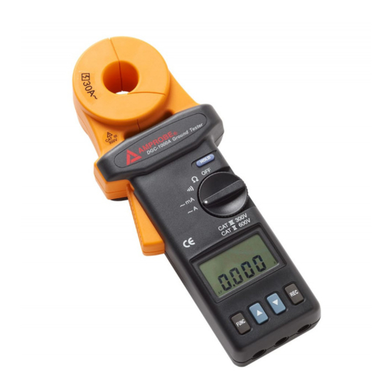
III. PANEL DESCRIPTION HOLD FUNC 1. Jaws Assembly: Enclose electrode or ground rod. No air gap is allowed between two half jaws. 2. Hold Button: Press this button to freeze the value in LCD 3. Rotary Switch: Turn power on and select the desired function. 4. -
Page 6: Lcd Display
IV. LCD DISPLAY 1. Function Display current selected function or current record number. 2. Digits Display value from 0 to 9999 with decimal point. 3. Ohm Symbol will be shown in and alarm functions. 4. mA Display ground leakage current in mA or A This symbol will be shown if the rotary switch is set at the alarm position. -
Page 7: Operation Instruction
V. OPERATION INSTRUCTION 5-1. Ground Resistance Measurement Open the jaws and make sure the jaws mating surfaces are clean and free of dust, dirt or any foreign substance. Snap the jaws closed a few times to let the jaws sit on the best mating position. - Page 8 ...R ...R GlobalTestSupply www. .com Find Quality Products Online at: sales@GlobalTestSupply.com...
- Page 9 GlobalTestSupply www. .com Find Quality Products Online at: sales@GlobalTestSupply.com...
-
Page 10: High And Low Alarm ( )
5-2. High and Low Alarm ( 1. Set the rotary switch to the position 2. Press the FUNC button to select “HI“ or “LO” alarm. The current value of High or Low alarm will be displayed on the upper row of the LCD. - Page 11 LOOP NOTE: If the HI value is set at OL, or the LO value is set at 0, the ALARM function will be disabled. So they are method to disable one of the HI or LO alarm. NOTE: The HI value can’t be smaller than the low value. And the LO value can’t be larger than the HI value.
-
Page 12: Ground/Leakage Current Measurement
5-3. Ground/Leakage Current Measurement 1. Turn the power on, and set the rotary switch at the mA or A position. 2. Clamp on to the electrode or ground rod. 3. Read the value of leakage current displayed in LCD. GlobalTestSupply www. -
Page 13: Setting The Sampling Interval
5-4. Setting the Sampling Interval 1. Press the FUNC button until letters of “SEC” are shown in the upper row of LCD. 2. The unit shows the current sampling interval in seconds. 3. Press the ▲ or ▼ button to increment/decrement the value by 1 second. -
Page 14: Read The Data Stored In Memory
5-6. Read the Data Stored in Memory Press the FUNC button until the symbol “NO” appears in the LCD. The current record number is shown in the upper row of LCD. And the data is displayed in the lower row of LCD. Press the ▲... - Page 15 circuit is shown in Figure A. If R , ... R are combined as R then only R and R are left in the circuit (refer to Figure B). If a constant voltage is applied to the circuit, the following equation will be derived.
- Page 16 ...R Figure A FigureB ...R GlobalTestSupply www. .com Find Quality Products Online at: sales@GlobalTestSupply.com...
-
Page 17: Electrical Specification
VII. ELECTRICAL SPECIFICATIONS Ground Resistance (Auto range) : Range Resolution Accuracy of Reading 0.025 - 0.250 0.002 ± 1.5% ± 0.05 0.250 - 1.000 0.02 ± 1.5% ± 0.05 1.001 - 9.999 0.02 ±... -
Page 18: General Specifications
VIII. GENERAL SPECIFICATIONS Conductor Size: 23mm (0.9”) approx. Battery Type: 9V IEC 6 LR61 (Alkaline) Display Type: 4 digits 9999 counts LCD Range Selection: Auto Overload Indication: Power Consumption: 40mA Low Battery Indication: Battery Life: 3000 measurements Sampling Time: 0.5 seconds Operating Temperature: 0 ... -
Page 19: Battery Replacement
IX. BATTERY REPLACEMENT When the low battery symbol is displayed on the LCD, replace the old battery with new battery. 1. Turn the power off. 2. Remove the screw of the battery cover. 3. Lift and remove the battery cover. 4. - Page 20 LIMITED WARRANTY Congratulations! Your new instrument has been quality crafted according to quality standards and contains quality components and workmanship. It has been inspected for proper operation of all of its functions and tested by qualified factory technicians according to the long-established standards of our company.
Need help?
Do you have a question about the DGC-1000A and is the answer not in the manual?
Questions and answers