
Related Manuals for Amprobe AMB-55


Summary of Contents for Amprobe AMB-55
- Page 1 AMB-55 5000V Insulation Resistance Tester Users Manual • Mode d’emploi • Bedienungshandbuch • Manual d’Uso • Manual de uso...
- Page 3 AMB-55 5000V Insulation esistance Tester Users Manual June 2011 , Rev.1 ©2011 Amprobe Test Tools. All rights reserved. Printed in China...
- Page 4 Limited Warranty and Limitation of Liability Your Amprobe product will be free from defects in material and workmanship for 1 year from the date of purchase, unless local laws require otherwise. This warranty does not cover fuses, disposable batteries or damage from accident, neglect, misuse, alteration, contamination, or abnormal conditions of operation or handling.
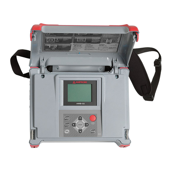
- Page 5 AMB-55 5000V Insulation Resistance Tester LCD Display Keypad START/STOP key to start or stop any measurement. ON/OFF key to switch the instrument ON or OFF. MEM key to store, recall and erase results. SELECT key to enter set-up mode for the selected function or to select the active parameter to be set.
- Page 6 AMB-55 5000V Insulation Resistance Tester Negative Insulation Resistance test terminal. (-OUT) GUARD test terminals intended to lead away potential leakage current while measuring the Insulation. Both green sockets are connected together inside the instrument. Positive Insulation Resistance test terminal (+OUT) �CAUTION! - Use original test accessories only!
-
Page 7: Table Of Contents
Dielectric Discharge Testing (DD) ......................18 Step voltage insulation resistance testing ..................21 Withstanding voltage ..........................24 Working with your Results ........................27 Transferring data to a PC ........................29 SPECIFICATIONS ............................33 MAINTENANCE AND REPAIR ........................35 Replacing and charging batteries ......................35 AMB-55 AND AMB-110 PC SOFTWARE INSTRUCTION MANUAL ............37... -
Page 8: Symbols And Warnings
SYMBOLS AND WARNINGS � Caution ! Risk of electric shock � Caution ! Refer to the explanation in this Manual � Double Insulation or Reinforced insulation � Alternating Current (AC). � Direct Current (DC). Fuse � Earth (Ground) Please remove all the test leads before preforming maintenance, cleaning, battery replacement, �... -
Page 9: Unpacking And Inspection
FEATURES The AMB-55 Tester is a portable battery / mains powered test instrument intended for the testing of Insulation Resistance by using high test voltages up to 5kV. The instrument is designed and produced with the extensive knowledge and experience acquired through many years of working in this sector. -
Page 10: Operation
- R(t) Graphs - Programmable timer (1s up to 99 min) - Automatic discharge of test object after completion of measurement - Capacitance measurement • Insulation resistance measurement versus test voltage (step-up voltage test) - Five discrete test voltages proportionately set within preset test voltage range - Programmable timer 1 min up to 99 min per step •... -
Page 11: Mains Powered Instrument Operation
Fig. 4. Auto-calibration state Fig. 5. Main Menu Note: If the instrument detects an incorrect state during the auto-calibration, the following warning message will be displayed: ERROR! • Test leads connected:Disconnect and switch on the instrument again • Conditions out of range: press start to continue Possible reasons for out of range conditions are excessive humidity, excessively high temperature, etc. -
Page 12: Off Function
Off function The instrument can be switched OFF only by pressing the ON/OFF key. The auto-off function is not available to allow long-term measurements to be performed. Configuration The configuration function enables the selection and adjustment of the parameters that are not directly involved in the measurement procedure (Fig. -
Page 13: Measurement
Adjustment of start of the timer in the DIAGNOSTIC TEST DIAG. Starting time 0%..90% functions, according the nominal voltage (Unominal). See additional explanation in the section of Diagnostic Test. Table 1. Configuration parameters MEASUREMENT General Information about High DC voltage testing The purpose of insulation tests nsulating materials are important parts of almost every electrical product. -
Page 14: Basic Insulation Resistance Test
IPI = polarization absorption current IRISO = actual insulation current IRISS = surface leakage current Some application examples for using AMB-55 Basic Insulation resistance test Virtually every standard concerning the safety of electrical equipment and installations requires the performance of a basic insulation testing. When testing lower values (in the range of Me), the basic insulation resistance (Riso) usually dominates. - Page 15 • Oiled paper used in transformers or motors is a typical insulation material that requires this test. In general, insulators that are in good condition will show a “high” polarization index while insulators that are damaged will not. Note that this rule is not always valid. General Applicable Values: PI value Tested material status...
-
Page 16: Humidity And Insulation Resistance Measurements
Humidity and insulation resistance measurements When testing outside the reference ambient conditions, the quality of the insulation resistance measurements can be affected by humidity. Humidity adds leakage paths onto the surface of the complete measuring system, (i.e. the insulator under test, the test leads, the measuring instrument etc). The influence of humidity reduces accuracy especially when testing very high resistances. -
Page 17: The Purpose Of Filtering
Fil0 Low pass filter with cut off frequency of 0.5 Hz in signal line. Fil1 Additional low pass filter with cut off frequency of 0.05 Hz in the signal line. Fil2 Fil1 with increased integrating time (4 s) Fil3 Fil2 with additional cyclic averaging of 5 results. Table 2. -
Page 18: Insulation Resistance Measurement
Measurement procedure: • Connect the test leads to the instrument and to the measured source. • Press the START key to start the measurement, continuous measurement starts to run. • Press the START key again to stop the measurement. • The result (see the right picture in Fig 10) can optionally be saved by pressing the MEM key twice, see the section of Store, Recall and Clear Operation. - Page 19 Initial display - graphical mode Display with results - graphical mode Fig. 12. Insulation Resistance function display states - Graph R(t) enabled Measurement procedure: • Connect the test leads to the instrument and to the test object. • Select INSULATION RESISTANCE function in MAIN MENU. •...
- Page 20 Fig. 13. Set-up menu in Insulation Resistance measurement Setting up parameters for Insulation Resistance test: • Press the SELECT key, the set-up menu will appear on the display, see the Fig 13. • Select the parameter (line) to be set using the h and i keys; •...
-
Page 21: Diagnostic Test
Enable/Disable the graph R(t) and Set-up the graph R(t) parameters in the Insulation Resistance function: • Press the SELECT key, Set-up menu appears on display, see the Fig. 14. • Select the parameter Graph R(t) to be set using the h and i keys; •... -
Page 22: Dielectric Absorption Ratio (Dar)
Fig. 17 shows states when Graph R(t) is enabled. After taking a measurement, you can switch back and forth between numerical mode display and graphical mode display by pressing h or i keys. h Graphical mode i Numerical mode Note: •... -
Page 23: Polarization Index (Pi)
Some applicable values: DAR value Tested material status < 1.25 Not acceptable < 1.6 Considered as good insulation > 1.6 Excellent Note: When determining Riso (15s) pay attention to the capacitance of test object. It has to be charged-up in the first time section (15s). Approximate maximum capacitance using: µF Where: t ..... -
Page 24: Dielectric Discharge Testing (Dd)
To avoid this problem, increase the DIAG. Starting time parameter in CONFIGURATION menu, because the start of timer in the DIAGNOSTIC TEST functions depends on the test voltage. The timer begins to run when test voltage reaches the threshold voltage, which is product of the DIAG. Starting time and nominal test voltage (Unominal). Analysing the change in the measured insulation resistance over time and calculating the DAR and PI are very useful maintenance tests of an insulating material. - Page 25 Notes: • A high-voltage warning symbol appears on the display during the measurement to warn the operator of a potentially dangerous test voltage. • The value of the capacitance is measured during the final discharge of the test object. • If enabled, the instrument measures Dielectric Discharge (DD) when the capacitance is in the range of 5 nF to 50 nF.
- Page 26 Time1 Time2 Time2 Time3 Fig. 19. Timer relations Fig. 20. Set-up menu in Diagnostic Test measurement Enable/Disable the graph R(t) and Set-up the graph R(t) parameters in the Diagnostic Test function: • Press the SELECT key, Set-up menu appears on display, see the Fig. 20. •...
-
Page 27: Step Voltage Insulation Resistance Testing
• The cursors of the Graph R(t) could be activated with f key. • The cursors of the Graph R(t) could be moved with f and g keys. �Warning! • Refer to Warnings chapter for safety precautions! Step Voltage Insulation Resistance testing Selecting this function displays the following states (initial state and state with results after the completion of the measurement). - Page 28 Initial display - graphical mode Display with results - graphical mode Measurement procedure: • Connect the test leads to the instrument and to the test object. • Press the START/STOP key to start the measurement. • Wait until set timer runs out, (the result will be displayed). •...
- Page 29 Displayed symbols: Fil0 (Fil1, Fil2, Fil3) Filter type enabled, see the chapter 5.3. Configuration 5000V Set test voltage – step 125 V U=5308V U=5308V Actual test voltage – measured value I=266nA Actual test current – measured value 19.9G Insulation Resistance – result C=1.2nF Capacitance of measured object Tm:05min 00s...
-
Page 30: Withstanding Voltage
• Complete the parameter adjustments by pressing either the ESC or the START/STOP key (to run the measurement directly). The settings displayed last will be saved Legend of displayed symbols: STEP VOLTAGE Name of selected function SETTING PARAMETERS: Unominal 5000V Set test voltage –... - Page 31 Fig. 28. Test voltage presentation without breakdown (left part) and with breakdown (right part) Ut ... Test voltage Ustop ..End test voltage Ustep ..Voltage step approx. 25 V (fixed value - not presetable) Ustart ..Starting voltage Tstep ..Test voltage duration per step Tend ..
- Page 32 Measuring procedure: • Connect the test leads to the instrument and to the measured object. • Press the START/STOP key to start the measurement. • Wait until the set timers runs out or until breakdown occurs, (the result will be displayed). •...
-
Page 33: Working With Your Results
Notes:Tstep and Tend are independent timers. The maximum time for each timer is 30 min 60 s. Tend begins after the completion of the ramp period. Ramp period can be calculated from: Tramp Tstep (Ustop– Ustart) / 25 V If Tstep is set to 00min 00s, then the ramp voltage increases by approximately 25 V every 2s. �Warning! •... - Page 34 To see the Graph R(t) press the SELECT key, to go back to the numerical measurement result press the ESC key. The recall function can be exited by pressing the ESC or Start key. • To clear the last stored result: highlight CLR and confirm by pressing the MEM key. To clear the complete memory see paragraph 4.2.
-
Page 35: Transferring Data To A Pc
Function name Last measured test voltage Set Start voltage Set Stop voltage Set trigger current value Actual test current - measured value Withstanding voltage DC Set Step test time Set End time Actual test time (at Stop test voltage) Ser. number of stored result Date * Time * Function name... -
Page 36: Insulation Resistance
How to transfer the stored data: Connect the instrument to the COM port of the PC using the communication cable (RS232 or USB). • Power up both the PC and the instrument. • In the CONFIGURATION menu of the instrument, set the communication mode (RS232 or USB) and Baud Rate appropriately. - Page 37 DC test voltage: Voltage value 250 V to 5 kV Accuracy -0 / +10 % + 20 V Output power 5 W max Display range Test voltage (V) Resolution Accuracy 0 - 5500 V ± (3 % of reading + 3 V) Current: Voltage value Resolution...
- Page 38 Dielectric absorption ratio DAR Display range DAR Resolution Accuracy 0.01 - 9.99 0.01 ± (5% of reading + 2digits) 10.0 - 100.0 ±(5% of reading) Polarization index PI Display range PI Resolution Accuracy 0.01 - 9.99 0.01 ± (5% of reading + 2digits) 10.0 - 100.0 ±(5% of reading) Dielectric discharge test DD...
-
Page 39: Specifications
Voltage Voltage AC or DC Display range External Voltage (V) Resolution Accuracy 0 - 600 ± (3 % of reading + 4 V) Frequency of external voltage Display range (Hz) Resolution Accuracy 0 and 45 - 65 0.1 Hz ±0.2 Hz Note: •... - Page 40 Environment Conditions Working temperature range -10 °C - 50 °C (14° - 122°F) Nominal (reference) temperature range 10 °C - 30 °C (50° - 86°F) Storage temperature range -20 °C - +70 °C (-4° - 158°F) Maximum humidity 90% RH (0 °C - 40 °C/ 32° - 104°F) non-condensing Nominal (reference) humidity range 40 % - 60 % RH Nominal altitude...
-
Page 41: Maintenance And Repair
MAINTENANCE AND REPAIR Inserting and charging batteries for the first time Battery cells are stored in the bottom section of the instrument casing under the battery cover (see Fig. 32). When inserting batteries for the first time please note the following: •... - Page 42 Fig. 32. Correct polarity of inserted batteries 1 .... Battery cover. 2 .... Screw (unscrew to replace the batteries). 3 .... Correct inserted batteries. Ensure batteries are used and disposed of in accordance with Manufacturers guidelines and in accordance with Local and National Authority guidelines.
-
Page 43: Amb-55 And Amb-110 Pc Software Instruction Manual
• The pop-up windows will guide you through the program setup process. INTRODUCTION AMBLink PRO program is a PC Software for AMB-55 and AMB-110 instruments. It is intended for downloading data from the instrument to PC and review downloaded data as a table or graph. The functionality for downloading is connected to the password, that is unique for instrument’s serial number. - Page 44 Language: enables you to select different program languages if there are more than one available. Password: enables you to add or remove password for communication with AMB-55 and AMB-110 instruments. You can add more different passwords to use only one PCSW for communication with more instruments.
- Page 45 USING PROGRAM Structure Editor Structure editor enables you to edit a structure and belonging measurements. You can delete items, change its settings (name), move subitems (measurements) from one item to another (move toolbutton should be in up position ) and move items up and down within its parent item (move toolbutton should be in down position When you drag item over another, the frame of the item is colored red, green or blue.
- Page 46 Structure Editor File presentation consists of structure tree and setting field on the left side and results table on the right side of the screen. Setting properties are connected to the selected item from the structure tree. It is possible to change Item name. Results are connected to the selected item from the structure tree.
- Page 47 Graph Graph command enables you to Print and Close graph. View command enables you Auto Range, Restore Range and Refresh Data. Print: prints graph Close: closes graph Auto Range: sets maximal value of Resistance X axis to optimal value due to max. resistance value. Restore Range: sets maximal value of Resistance X axis to original value.
- Page 48 Table Table command enables you to Print and Close table. Print: prints table. Close: closes table. Measurement table represents 12 points of measurement graph. Table data belongs to time 15sec, 30sec and 1min to 10min time. If the data at specific time is not available, 5s plus or minus is taken into account. Functionality is available for all different measuring functions, except for STEP VOLTAGE.
- Page 49 Print Header (Header, Comment, Footer) 1. Report header appears at the beginning of the first page of PRO report. There are five fields to define: • Operator (the person who performed tests), • Test site (location where tests were performed), •...
- Page 50 Report print preview Report print preview form shows measured results in PRO REPORT form completed with Report header, Report comments and Page footer. This is the form that will appear on the printed PRO report. From print preview window you can set up printer and print PRO report by clicking on the appropriate icon Export Format of the text file is defined in the Export Format window that is shown automatically after selecting File / Export from Main Menu command of Main Screen.
Need help?
Do you have a question about the AMB-55 and is the answer not in the manual?
Questions and answers