
Related Manuals for Amprobe BAT-500


Summary of Contents for Amprobe BAT-500
- Page 1 BAT-500 Battery Impedance Tester Users Manual • Mode d’emploi • Bedienungshandbuch • Manual d’Uso • Manual de uso...
- Page 2 BAT-500 Battery Impedance Tester Users Manual July 2009, Rev.1 ©2009 Amprobe Test Tools. All rights reserved. Printed in Taiwan...
- Page 3 Limited Warranty and Limitation of Liability Your Amprobe product will be free from defects in material and workmanship for 1 year from the date of purchase. This warranty does not cover fuses, disposable batteries or damage from accident, neglect, misuse, alteration, contamination, or abnormal conditions of operation or handling. Resellers are not authorized to extend any other warranty on Amprobe’s behalf.
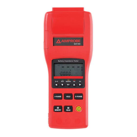
- Page 4 BAT-500 Battery Impedance Tester...
- Page 5 BAT-500 Battery Impedance Tester Keys And Input / Output Terminals POWER key : Power on / off READ key : 1) Press key to show the manual logged readings. 2) Press READ key again to stop reading. MEMORY key :...
- Page 6 BAT-500 Battery Impedance Tester Display The reading of the measured impedance (High or Low limit of impedance on the comparator settings) The reading of the measured voltage (High or Low limit of voltage on the comparator settings) The assigned number of comparator : 99 sets The location for the manual logged data mΩ...
- Page 7 BAT-500 Battery Impedance Tester LEDS Display PASS To indicate the tested battery complies with the high limit (Green LED) of comparator. WARNING To indicate that the tested battery is going to deteriorate. (Yellow LED) FAIL To indicate that the tested battery has deteriorated.
-
Page 8: Table Of Contents
BAT-500 Battery Impedance Tester CONTENTS SYMBOLS .......................2 UNPACKING AND INSPECTION ................2 INTRODUCTION .....................3 OPERATION ......................3 Preparation ......................3 Operation ......................4 Zero Adjust (REL) ....................5 Using Comparator function (99 sets) ...............5 Comparator Settings ..................5 Comparator Tables ....................6 Start / Stop Controls the Comparator ..............6 Start / stop data logging ...................7... -
Page 9: Symbols
SYMBOLS Caution ! Refer to the Complies with European � � explanation in this Manual Directives Do not dispose of this Conforms to relevant � product as unsorted Australian standards. municipal waste WARNING! � Do not operate the meter in explosive gas (material), combustible gas (material) steam or filled with dust. -
Page 10: Introduction
INTRODUCTION • The Battery Tester is designed for measuring the internal impedance and open-circuit voltage of the secondary battery including Nickel-metal hydride battery (NiMH), Nickel-cadmium battery (NiCd), Lithium-ion battery (Li-ion), Alkaline battery and Lead-Acid battery. • AC four-terminal method to measure the internal impedance by eliminating lead impedance and contact impedance to get the accurate results. -
Page 11: Operation
Operation WARNING! � • Do not attempt to measure DC voltage exceeding 50V. Do not attempt to measure AC voltages. This could result in injury or damage to the unit. • Do not attempt to measure the voltage of a generator. This would result in an AC voltage being applied to the voltage generating output terminals, which is dangerous. -
Page 12: Zero Adjust (Rel)
Zero Adjust (REL) The zero adjustment function is to zero the range of impedance and voltage. The reading during zero adjustment will be taken as zero and will be used to calibrate subsequent measurements. 1. Short the red and black test leads probe 4 terminals. 2. -
Page 13: Comparator Tables
6. Press u key one time, the high limit impedance of the “two higher digits” will be flashing. (Use the p & q keys to select the desired value.) 7. Press u key one time, the high limit impedance of the “two lower digits”... -
Page 14: Start / Stop Data Logging
Start / Stop Data Logging Erasing Memory When memory is full, “Full” symbol will appear on the display and logging will be stopping. 1. Press key to turn off the tester. 2. Press and hold MEMORY key, then press key until the display shows CIr to delete all logged reading in the memory. -
Page 15: Specification
SPECIFICATIONS General Specifications Measuring method : Impedance (AC four-terminal method). A/D conversion : Dual slope method. Display : Dual display LCD and LEDs (comparator output). Sampling rate : 1 set (impedance and voltage measurements) / second. Open-Circuit terminal voltage : 3.5Vpp max. Input over range : “OL”... - Page 16 Maximum altitude value usable: 2000m or less. Size : 250 (L)mm × 100(W)mm × 45(T)mm (9.8(L)in x 3.9 (L)in x 1.8(L)in) Weight : 500g / 1.1Lb approx. (including batteries) Accessories : Test Leads, Instruction Manual, Batteries, Software CD, RS-232 Cable, Carrying Case. Option : AC adaptor (9V DC output), minimun 1.6 Amp, 15W, DC IN Jack Polarity: Center (-), Outer (+) �...
-
Page 17: Electrical Specifications
Electrical Specifications Conditions to guarantee accuracy °C °C (73.4 Temperature : 23 ± 5 °F ±41°F) Humidity : 80%RH or less (no condensation). Zero adjustment : After zero adjustment for each range. Impedance measurement °C Temperature coefficient : (±0.1% rdg ± 0.5dgs) / Measuring current frequency : 1KHz ±... -
Page 18: Maintenance And Repair
MAINTENANCE AND REPAIR If there appears to be a malfunction during the operation of the meter, the following steps should be performed in order to isolate the cause of the problem. 1. Check the battery. Replace the battery immediately when the symbol “ ”... -
Page 19: Rs-232 Interface, Software Installation And Operation
RS-232 INTERFACE, SOFTWARE INSTALLATION AND OPERATION RS-232 Wiring Diagram Meter Side PIN 2 RX PIN 3 TX PIN 4 DTR PIN 5 GND PIN 6 DSR PIN 7 RTS PIN 8 CTS Computer Side(Female) RS-232 Connector Diagram 9 to 25 pins Wiring Diagram RS-232 Default Settings If 9 pins COM port is occupied, the 9 When RS-232 communication... -
Page 20: Rs-232 Protcode
RS-232 PROTOCOL Transmitting Byte Code Byte1 Byte2 Byte3 Byte4 Byte5 Byte6 Byte7 Voltage Status Byte1: Starting Byte ( 02 ) Byte2, Byte3 : Ohm Bytes Byte4, Byte5 : Voltage Bytes Byte6 : Status Bytes Bit7 Bit6 Bit5 Bit4 Bit3 Bit2 Bit1 Bit0 ----(Ohm) -
Page 21: Software Requirements And Setup
SOFTWARE REQUIREMENTS AND SETUP 1) Start up windows 98 / 2000 / XP operating system 2) Close all other applications 3) Insert disk in CD drive Wait for “Autorun” to start and follow on-scree instructions (If “autorun” does not sart, click on “Start” then “Run”. Type the drive letter and “: \Disk1\Setup.exe”... - Page 22 a. Click Next> button to setup on the default folder or b. Click Browse…button to setup on a different folder Click Next> button Setup is completed.
-
Page 23: Communicating Operation
COMMUNICATING OPERATION Run the software 1. Click “Start” form Start menu and then move to “Programs” then “BatTester” and then click the “BatTester” icon. 2. Click an available COM port 3. Main software screen If no connection, then shows below The right bottom side shows... -
Page 24: Record
RECORD ( SAVE TO HDD) Click button. The dialog box shown below will appear. Input a file name and then click “Save” to begin saving data to the file just named. Click button to stop recording. -
Page 25: Download
DOWNLOAD DATA 1.Download Data from EEP ROM (to read automatically recorded data) Click button. The Data Logger window, shown below, will open. Click on a SET number to view the set’s details. For example, in the window above, there are 2 sets from which to choose. -
Page 26: Data Convert
DATA CONVERT Apply for Excel Open Microsoft Excel, find the file saved in Excel type, for example, test.xls. EMBED PBrush or find any file already saved in HDD, for example, sample.dat.(see below) - Page 27 EMBED PBrush The “Text Import Wizard” then appears. Follow the steps 1 to 3 to complete. Click Next> button Click “Next” Click Finish to complete.
-
Page 28: Apply For Excel
Apply for Graph Open a saved data in HDD or EEP ROM, click button to complete. SAMPLING TIME PC Sampling Rate: Click button on the Menu Bar. In the Input Sampling Time dialog box, input the willing sampling time and then click“OK”...
Need help?
Do you have a question about the BAT-500 and is the answer not in the manual?
Questions and answers