Table of Contents
Advertisement
Quick Links
Advertisement
Table of Contents

Related Manuals for Amprobe GP-2 GeoTest


Summary of Contents for Amprobe GP-2 GeoTest
- Page 1 GP-2 GeoTest EN - 1...
-
Page 2: Table Of Contents
GP-2 GeoTest PRECAUTIONS AND SAFETY MEASURES ..............3 1.1. PRELIMINARY INSTRUCTIONS..................3 1.2. DURING USE ........................4 1.3. AFTER USE......................... 4 GENERAL DESCRIPTION.....................5 2.1. INSTRUMENT DESCRIPTION ................... 6 PREPARING THE INSTRUMENT ..................8 3.1. INITIAL CHECK........................8 3.2. POWER SUPPLY........................ 8 3.3. -
Page 3: Precautions And Safety Measures
GP-2 GeoTest 1. PRECAUTIONS AND SAFETY MEASURES This instrument complies with European Community (EC) standards: EN61557-1, EN61557-5 and EN 61010-1. WARNING: For your safety as well as that of the instrument you are recommended to follow the procedures described in this... -
Page 4: During Use
GP-2 GeoTest F Use the instrument in TT, TN, IT system and industrial, civil, medical electrical plants, in normal conditions (contact voltage limit 25V) and in particular condition (contact voltage limit 50V). Do not take measurements on circuits exceeding the specified current and voltage limits. -
Page 5: General Description
EARTH 2 WIRES: 2 wires earth resistance EARTH 3 WIRES: 3 wires earth resistance ρ ρ 4 wires earth resistivity The GP-2 GeoTest uses the "Fall of potential" method of measurement for all of the above tests. EN - 5... -
Page 6: Instrument Description
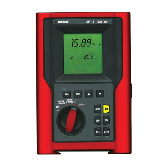
GP-2 GeoTest 2.1. INSTRUMENT DESCRIPTION DIST Rotary switch: Permits selection of the desired function DISP R C L SAVE Figure 1: Front panel EN - 6... - Page 7 GP-2 GeoTest Displays the average value of the earth resistivity, calculated on the basis of all valid measurements taken. DIST Selects the distance "D" between the earth rods (ρ resistivity test). Increases the value of the parameter D; Scrolls through the recorded test results;...
-
Page 8: Preparing The Instrument
GP-2 GeoTest 3. PREPARING THE INSTRUMENT 3.1. INITIAL CHECK This instrument has been carefully checked for proper electrical and mechanical function prior to shipment. All possible precautions have been taken in order to deliver it in the best possible condition. -
Page 9: Switch Functions
GP-2 GeoTest 4. SWITCH FUNCTIONS 4.1. EARTH 2 WIRES Whenever it is not possible to drive rods into the ground to take a 3-wire measurement, or in case of TT installations it is possible to use the simplified 2-wire method (Figure 2) which gives an excess (therefore safer) value. - Page 10 GP-2 GeoTest Press GO to take the measurement and read the result on the display. At the end of the test, a screen similar to the following will be displayed. NOTE! If you keep pressing GO, the instrument takes more measurements consecutively.
- Page 11 GP-2 GeoTest secondary display on the left-hand side = 003 (no. of measurements = 3 means that 3 earth measurements have been taken consecutively) secondary display on the right-hand side = average of the measurements taken ((Val1+Val2)/no. of measurements = (0.90+0.96+0.93)/3 = 0.93Ω) NOTE! A test with a result over 700Ω...
-
Page 12: Earth 3 Wires
GP-2 GeoTest 4.2. EARTH 3 WIRES The measurement is taken according to what is prescribed for CEI 64.8, IEC 781, VDE 0413, EN61557-5 standards. Small earth plant: current probe (terminal H, blue wire) positioned a distance from earth equipment outline... - Page 13 GP-2 GeoTest secondary display on the left-hand side is updated. This counter indicates the quantity of measurements included in the calculation of the average resistance value. 0.96 0.96 Value of the resistance Ω Ω measured earth resistance measurements included calculation of the average resistance 0.93...
- Page 14 GP-2 GeoTest NOTE! A test with a result over 700Ω is not inserted in the calculation of average value. Example: measurement Main display: 1,07Ω Secondary display on the left-hand side: 1 Secondary display on the right-hand side: 1,07Ω measurement Main display: 4,15Ω...
-
Page 15: Ρ" Mode (Resistivity Of The Earth)
GP-2 GeoTest "ρ ρ " MODE (Resistivity of the Earth) 4.3. The measurement is taken according to CEI 64.8, IEC 781, VDE 0413, EN61557-5 standards. 4.3.1. Selecting the units of measure WARNING Whenever the units of measure are changed the instrument will perform a hard reset and all the data in the memory will be erased (see paragraph 6.1). - Page 16 GP-2 GeoTest ρ ρ Position the switch on Display appearance: ft or m ρ ρ ft/m To select the distance D between the rods. This parameter can be chosen from DIST the following values (expressed in ft/m): 3, 6, 9, 12, 15, 18, 21, 24, 27, 30...
- Page 17 GP-2 GeoTest NOTE! Regardless on the unit of distance D, which is set up (either ft or m) the resistivity will be automatically calculated in OhmMeters! WARNING: When the message “Measuring” appears on the display, the instrument is measuring. Do not disconnect the alligator...
- Page 18 GP-2 GeoTest SAVE Press SAVE to store the test results in memory (see paragraph 5.1). Example: You position the rods at a distance D of 3 feet and take 3 resistivity measurements: Ω Ω m ρ ρ Ω Ω m ρ ρ...
-
Page 19: Anomalous Situations Which Can Occur During Tests
GP-2 GeoTest 4.4. ANOMALOUS SITUATIONS WHICH CAN OCCUR DURING TESTS WARNING If the voltmetric circuit (red and green - - - - - - cables) is interrupted, when pressing ν ν GO the instrument will not read the minimum voltage, therefore a screen similar to the one beside appears. - Page 20 GP-2 GeoTest In case both the amperometric WARNING circuit and the voltmetric circuit - - - - - - ν ν are interrupted, when pressing GO the instrument will not read the minimum current nor the minimum voltage, therefore a screen similar to the one beside appears.
- Page 21 GP-2 GeoTest instrument measures WARNING interfering voltage higher than 30V - - - - - - ν ν on the amperometric circuit, it does not perform the test and a screen similar to the one beside appears. - - - UC indicates the presence of too high voltage on the amperometric circuit.
-
Page 22: How To Save, Recall And Cancel Data
GP-2 GeoTest 5. HOW TO SAVE, RECALL AND CANCEL DATA 5.1. TO SAVE: "SAVE" KEY If you want to save the test results: SAVE Press SAVE once. A screen similar to the one beside is displayed seconds, instrument emits a sound, then the screen corresponding to the last measurement taken is displayed. -
Page 23: To Recall: "Rcl" Key
GP-2 GeoTest 5.2. TO RECALL: "RCL" KEY If you want to review the test results: Press RCL. memory contains measurements, a screen similar to the one beside will be displayed. No. of last memory location occupied. If the memory is empty, a screen similar to the one beside will be displayed. -
Page 24: To Cancel: "Clr" Key
GP-2 GeoTest 5.3. TO CANCEL: "CLR" KEY If you want to delete the test results: Press RCL. A screen similar to the following will be displayed: No. of the last memory location occupied. Press t t , s s to select the number of the memory location. - Page 25 GP-2 GeoTest Press ESC again to return to the selected measuring function. Ex.: 97 test results have been saved. You want to clear from the 43 to the 97 location. - Press RCL. memory location using t and s. - Select the 43 - Press CLR.
-
Page 26: Reset And Default Parameters
GP-2 GeoTest 6. RESET AND DEFAULT PARAMETERS This paragraph describes the HARD RESET procedure and the default parameters set when a HARD RESET procedure is performed. 6.1. HARD RESET NOTE! BEFORE RESETTING, TRANSFER ALL SAVED DATA TO A PC. 1. Depress and hold the CLR key while turning on the instrument by rotating the switch. -
Page 27: Connecting The Instrument To A Pc
GP-2 GeoTest 7. CONNECTING THE INSTRUMENT TO A PC Connect the instrument to a PC through the RS-232 port with the supplied cable. Refer to software manual for information how to set up software for download. In order to transfer recorded data to a PC follow this procedure: Position the switch on RS232. -
Page 28: Maintenance
8. MAINTENANCE 8.1. GENERAL GP-2 GeoTest is a precision instrument. During its use and for its storage follow the recommendations and instructions contained in this manual in order to avoid possible damage or danger. Never use the instrument in environments with a high humidity or temperature. -
Page 29: Technical Specifications
GP-2 GeoTest 9. TECHNICAL SPECIFICATIONS 9.1. TECHNICAL FEATURES Resistance measurement Range (**) Resolution Accuracy (*) (Ω Ω ) (Ω Ω ) 0.01 ÷ 19.99 0.01 20.0 ÷ 199.9 ±(2% reading + 3 digits) 200 ÷ 1999 (*) If R > 100R and/or R >... - Page 30 GP-2 GeoTest Resistivity measurement ρ ρ Range (**) Resolution Accuracy (*) 0.6-125.6 Ωm 0.1 Ωm 0.125 – 1.256 kΩm 0.001 kΩm ±(2% reading + 3 digits) 1.25-19.99 kΩm 0.01 kΩm 20.0 – 199.9 kΩm 0.1 kΩm (*) If R > 100R and/or R >...
-
Page 31: General Features
GP-2 GeoTest General features Mechanical features Dimensions: 222 (L) x 162 (W) x 57 (H) mm Weight (batteries included): about 1000g Power supply Batteries: 6 batteries 1.5 V size AA ( LR6 –– AM3 – MN 1500) Low battery indication:... -
Page 32: Operating Conditions
GP-2 GeoTest 9.2. OPERATING CONDITIONS 9.2.1. Environmental conditions Reference temperature: 73 ± 41 F (23° ± 5°C) Operating temperature: 14 ± 122 F (-10°C ÷ 50 °C) Relative humidity: <80% Storage temperature: -4 ± 140 F (-20 ÷ 60 °C) Storage humidity: <70%... -
Page 33: Service
GP-2 GeoTest 10. SERVICE 10.1. WARRANTY This instrument is guaranteed against any defects in material and manufacturing for one year, in compliance with the general sale terms and conditions. During the warranty period all defective parts may be replaced, but the manufacturer reserves the right to repair or replace the product. - Page 34 GP-2 GeoTest A report should accompany the returned product, stating the reason(s) for return. The unit should be packed in its original carton or equivalent; any damage that may be due to non-original packing shall be charged to the customer.
-
Page 35: Practical Reports For Electrical Tests
GP-2 GeoTest 11. PRACTICAL REPORTS FOR ELECTRICAL TESTS 11.1. EARTH RESISTANCE MEASUREMENT PURPOSE OF THE TEST This test is carried out to make sure that the protective device is coordinated with the earth resistance value. You cannot take off hand a limit earth resistance value as a reference for the test result: occasionally you must make sure that the prescribed coordination is respected. - Page 36 GP-2 GeoTest EXAMPLE OF EARTH RESISTANCE MEASUREMENT You must test equipment protected by a RCD at 30 mA. Measure the earth resistance according to one of the above-described methods. In order to check whether the resistance complies to the standards in force, multiply the value for 0.03A (30 mA). If the result is lower than 50V (or 25V for special places) the equipment is to be considered as coordinated as it meets the above stated requirement.
- Page 37 GP-2 GeoTest For large earth plants This procedure is also based on the voltamperometric method, but it is mainly used when it is difficult to position the auxiliary current rod at a distance corresponding to five-times the diagonal of the area of the earth equipment. Position the current probe at a distance equal to the diagonal of the area of the earth equipment (see Figure 6).
-
Page 38: Earth Resistivity Measurement
GP-2 GeoTest 11.2. EARTH RESISTIVITY MEASUREMENT PURPOSE OF THE TEST This test is intended to analyze the resistivity value of the ground in order to define the type of rods to be used. EQUIPMENT PARTS TO BE TESTED For the resistivity test admissible values do not exist. The various values measured by positioning the rods at growing distances “a”... - Page 39 GP-2 GeoTest The measuring method allows definition of the specific resistance up to the depth approximately corresponding to the distance “a” between the rods. If you increase the distance “a” you can reach deeper ground layers and check the ground homogeneity. After several ρ...
- Page 40 GP-2 GeoTest parallel, especially if those elements are close and therefore interactive. For this reason, in case of a linked system the following formula is quicker and more effective than the calculation of the single horizontal and vertical elements: Rd = ρ / 4r r= radius of the circle which circumscribes the link.
- Page 41 AMPROBE MIAMI, FL Tel: 305 423 7500 Fax: 305 423 7554 www.amprobe.com Tecnical Support: www.amprobe.com 800 327 5060...
Need help?
Do you have a question about the GP-2 GeoTest and is the answer not in the manual?
Questions and answers