Table of Contents
Advertisement
Quick Links
Advertisement
Table of Contents

Related Manuals for Amprobe DMIII


Summary of Contents for Amprobe DMIII
- Page 1 Copyright Amprobe 2005...
-
Page 3: Table Of Contents
DMIII MULTITEST INDEX 1. SAFETY PRECAUTIONS AND PROCEDURES ..................4 1.1. Forwards .................................. 4 1.2. Preliminary Instruction ............................. 4 1.3. During Use ................................5 1.4. After Use .................................. 5 2. GENERAL DESCRIPTION ........................... 6 2.1. Introduction ................................6 2.2. Functions ................................. 6 3. - Page 4 DMIII MULTITEST 7.4. "VOLTAGE" function .............................. 47 7.4.1. Symbols ...................................47 7.4.2. "METER" mode ................................48 7.4.3. "HARM" mode ..................................49 7.4.4. "WAVE" mode ..................................51 7.5. "CURRENT" function ............................. 52 7.5.1. Symbols ...................................52 7.5.2. “METER" mode ................................53 7.5.3. “HARM" mode ..................................54 7.5.4. "WAVE" mode ..................................56 7.6.
- Page 5 DMIII MULTITEST 16.1. Continuity Test On Protective Conductors ......................82 16.2. Check of the Circuit Separation ..........................83 16.3. Measurement Of Floor Insulation Resistance In Medical Rooms Cei 64-4 ............86 16.4. Ground Resistance Measurement ......................... 88 16.5. Ground Resistivity Measurement ........................... 89 16.6.
-
Page 6: Safety Precautions And Procedures
(building yards, swimming pools, etc.) and 50V in ordinary places because of the risk of electric shock; Use only cables and accessories approved by Amprobe; The following symbols are used in this manual: Caution: refer to the instructions in this manual; improper use may damage the apparatus or its components. -
Page 7: During Use
DMIII MULTITEST Please keep to the usual safety standards aimed at: Protecting against dangerous currents; Protecting the instrument against incorrect operations. Only the accessories supplied with the instrument guarantee compliance with the safety standards. Accordingly, they must be in good conditions and, if necessary, they must be replaced with identical models. -
Page 8: General Description
DMIII MULTITEST 2. GENERAL DESCRIPTION 2.1. INTRODUCTION Dear Customer, we thank you for your patronage. The instrument you have just purchased will grant you accurate and reliable measurements provided that it is used according to the present manual’s instructions. The instrument was designed to grant the user the utmost safety conditions thanks to a new concept assuring double insulation and over voltage category III. -
Page 9: Preparation For Use
An external power supply adapter (code DMT-EXTPS) to be used only for POWER QUALITY functions. We recommend that you use only DMT-EXTPS Amprobe Power Supply adapter. For your own safety you’re not able to use the external power supply adapter during Safety Test (LOW, INSULATION TEST,... -
Page 10: Calibration
DMIII MULTITEST WARNING For recordings (POWER QUALITY function) ALWAYS use the external power supply adapter (code DMT-EXTPS) even the instrument allows the operator to perform a recording using internal batteries. If during a recording the external power supply adapter is de-energized, the instrument will... -
Page 11: Instrument Description
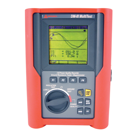
DMIII MULTITEST 4. INSTRUMENT DESCRIPTION LEGEND: Display Function Keys Rotary switch START STOP HOLD SAVE ENTER MENU Front panel of the Instrument Multifunction Keys. ON/OFF and backlight key. Press it for few seconds to switch OFF the ON / OFF instrument, press it briefly to activate the backlight function. -
Page 12: Display Description
DMIII MULTITEST 4.1. DISPLAY DESCRIPTION The display is a graphic module with a resolution of 128 x 128 pixels The first line of the display shows date and time. If not correct, you can set the exact ones according to the procedure described at paragraph 5.2. -
Page 13: Initial Settings
DMIII MULTITEST 5. INITIAL SETTINGS By pressing the MENU key the following screen will be displayed: MENU GENERAL SAFETY TEST MEMORY ANALYZER MEMORY RESET ANALYZER CONFIG RECORDER CONFIG CONTRAST DATE&TIME LANGUAGE COUNTRY It’s not possible to enter the MENU during a recording or a Real Time Energy measurement. -
Page 14: Reset
DMIII MULTITEST 5.5. RESET This option re-establishes the default settings of the instrument. ANALYZER CONFIG: Type of electrical equipment: Three Phase 4 wires Frequency: not modified Clamp full scale: not modified Clamp type: not modified Transforming ratio of voltmetric transformers:... -
Page 15: Safety Test Functions
DMIII MULTITEST 6. SAFETY TEST FUNCTIONS 6.1. LOW: CONTINUITY TEST WITH 200mA TEST CURRENT The measurement is taken according to EN 61557-2 and VDE 0413 part 4. WARNING Before carrying out the continuity test be sure that there is no voltage at the ends of the conductor under test. -
Page 16: Calibrating The Test Leads ("Cal" Mode)
DMIII MULTITEST 6.1.1. Calibrating the test leads ("CAL" Mode) 1. Connect the black and yellow test leads to T1 and T4 input terminals respectively. (V1) (V2) (V3) (COM) Connection of instrument terminals during calibration procedure. 2. If the test leads supplied with the instrument are not long enough for the measurement you can extend the black cable. - Page 17 DMIII MULTITEST TEST LEADS Before each measurement always assure that the calibration is for the cables in use. During a continuity test, if the resistance value free of calibration (that is the resistance value less the calibration offset value) is negative, the symbol...
-
Page 18: Measurement Procedure
DMIII MULTITEST 6.1.2. Measurement Procedure 1. Select the desired mode using the F1 key. 2. Connect the black and yellow test leads to T1 and T4 input terminals respectively (V1) (V2) (V3) (COM) Connection of the test leads during LOW test. -
Page 19: Results Of "Auto" Mode
DMIII MULTITEST 6.1.3. Results of "AUTO" mode At the end of the test, if LOW 05.06.01 Average resistance value (Ravg) the average resistance value Ravg is lower than 5 the instrument emits a double sound 1.05 signal indicating Resistance... - Page 20 DMIII MULTITEST EN-18...
-
Page 21: Auto", Rt+", "Rt-" Faulty Cases
DMIII MULTITEST 6.1.5. "AUTO", RT+", "RT-" faulty cases If the instrument detect LOW 05.06.01 External Power supply adapter connected to instrument Disconnect the External Power Supply Adapter will show the message .- - displayed to the right. --- ---... - Page 22 DMIII MULTITEST THE PREVIOUS RESULTS CAN'T BE SAVED. If LOW 05.06.01 value Resistance value higher than 5 Resistance is higher than 5 (but lower than 99.9) the instrument 5.17 emits a long beep and displays a screen similar...
-
Page 23: Insulation Test: Insulation Resistance Measurement
DMIII MULTITEST 6.2. INSULATION TEST: INSULATION RESISTANCE MEASUREMENT The measurements comply with IEC 61557-2 and VDE 0413 part 1. ATTENTION Before performing an insulation test make sure that the circuit under test is not energised and all the loads are disconnected. - Page 24 DMIII MULTITEST Standard Brief description Test voltage Maximum limit value > 0.250M Systems SELV or PELV 250VDC CEI 64-8/6 Systems up to 500V (Civil installations) 500VDC > 0.500M Systems over 500V 1000VDC > 1.0M Floor and wall insulation in civil installations 500VDC >...
-
Page 25: Results Of "Man" Mode
DMIII MULTITEST 6.2.2. Results of "MAN" mode At the end of the test if M 05.06.01 Insulation Resistance insulation resistance lower Voltage during the Test than R (see Table2) instrument 1.07 Duration of the Test M generates Nominal test Voltage,... -
Page 26: Results Of "Tmr" Mode
DMIII MULTITEST 6.2.3. Results of "TMR" mode At the end of the test if M 05.06.01 Insulation Resistance Insulation resistance lower Voltage during the Test than R (see Table2) instrument 1.07 Duration of the Test generated Nominal test Voltage,... -
Page 27: Man" And "Timer" Mode Faulty Cases
DMIII MULTITEST 6.2.4. "MAN" and "TIMER" mode faulty cases If M 05.06.01 instrument detects the External Power supply adapter -.- - instrument will Disconnect External Power Supply Adapter show the message displayed to the right. ---V REMOVE POWER 500V... -
Page 28: Phase Sequence Indicator
DMIII MULTITEST The displayed result can be stored by pressing the SAVE key twice (refer to paragraph 9.1). 6.3. PHASE SEQUENCE INDICATOR Turn the rotary knob to the position. 6.3.1. Measurement procedure and results of " " mode 1. Connect the Black, Red and Blue connectors of the split cables to their corresponding input terminals of the instrument T1, T2, T3. - Page 29 DMIII MULTITEST EN-27...
-
Page 30: Faulty Cases
DMIII MULTITEST 6.3.2. Faulty Cases In the " LOOP 05.06.01 " mode, if a Phase-to-Phase voltage is lower than 100V, the instrument displays the screen to the right. FRQ =60.0HZ V1-2=111V V2-3= V3-1= LOW VOLTAGE T Phase "T2 Voltage is lower than 100V PHASE ROTATION ... - Page 31 DMIII MULTITEST This result can be stored pressing the SAVE key twice (refer to paragraph 9.1). EN-29...
-
Page 32: Ground Test: Soil Resistance And Resistivity Measurements
DMIII MULTITEST 6.4. GROUND TEST: SOIL RESISTANCE AND RESISTIVITY MEASUREMENTS Turn the rotary knob to the GROUND TEST position. The F1 key permits to select one of the following measuring modes (which can be shown cyclically when pressing the key): ... - Page 33 DMIII MULTITEST At the end of the test the instrument emits a EARTH 05.06.01 double beep indicating Ground Resistance value expressed in . that test correctly terminated and displays the values Voltage value of electrical 0.77 noise to the right.
-
Page 34: Measurement Procedure And Results Of
DMIII MULTITEST 6.4.2. Measurement procedure and results of " " mode 1. Select measurement mode by means of the F1 key. 2. Select the distance d between the earth rods by means the F3 and F4 keys. The Distance measuring unit comply with Country setting (see par. 5.4). - Page 35 DMIII MULTITEST EN-33...
-
Page 36: 2-W", "3-W" And " " Faulty Cases
DMIII MULTITEST 6.4.3. "2-W", "3-W" and " " faulty cases If the instrument detects EARTH 05.06.01 External Power supply adapter connected to instrument Disconnect the External Power Supply Adapter will show the message displayed to the right. - Page 37 DMIII MULTITEST THE PREVIOUS RESULTS CANNOT BE SAVED. If Instrument detects a Resistance EARTH 05.06.01 value higher than Message ">1999" means that the resistance value is higher 1999, the instrument than maximum will show the screen to > 1999 ...
-
Page 38: Power Quality
DMIII MULTITEST 7. POWER QUALITY This function allows the following operations: display in real time the electrical parameters of a single phase system or a three phase system (with and without neutral wire) and the harmonic analysis of voltage and current. -
Page 39: Basic Setting: Analyzer Config
DMIII MULTITEST 7.1. BASIC SETTING: ANALYZER CONFIG Place the rotary switch in the POWER QUALITY position, press the MENU key, using the F1/F2 keys select the ANALYZER CONFIG item and press the ENTER Key. The following page will be displayed:... -
Page 40: How To Set The Clamp Type
DMIII MULTITEST 7.1.3. How to set the Clamp Type The value of this parameter must be always equal to the type of clamp being used. Three types of clamps are available: STD: STANDARD clamps or current transformers FlexEXT: FLEXIBLE clamps with EXTERNAL power supply. -
Page 41: Basic Setting: Recorder Config
DMIII MULTITEST 7.2. BASIC SETTING: RECORDER CONFIG Place the rotary switch in the POWER QUALITY position, press the MENU key, using the F1/F2 keys select the RECORDER CONFIG item and press the ENTER Key. This option allows you to check and eventually modify the recording parameters and the selected parameters (up to a maximum of 62+Frequency). - Page 42 DMIII MULTITEST To Select MANUAL or AUTOMATIC MENU start/stop mode, place the cursor on RECORDER CONFIG MANU AUTO using multifunction key F1 or F2 and select START MANU the desired mode using F3 or F4. STOP Use the multifunction keys F1, F2...
- Page 43 DMIII MULTITEST From 2 page of RECORDER CONFIG MENU ENTER Use the multifunction keys F1, F2 to position the cursor on the desired word RECORDER CONFIG multifunction keys F3 / F4 CURRENT: to modify the value or I1 I2 I3 IN select / deselect the desired parameter (it’s...
- Page 44 DMIII MULTITEST From 3 page of RECORDER CONFIG MENU ENTER RECORDER CONFIG CO-GENERATION:ON POWER:Pg ENERGY:Pg Example of 4 page In order to select the POWER to be recorded use the multifunction keys F1, F2 to position the cursor on the ...
- Page 45 DMIII MULTITEST From 3 page of RECORDER CONFIG MENU ENTER RECORDER CONFIG CO-GENERATION:ON POWER:Pg ENERGY:Pg Example of 4 page In order to select the ENERGIES to be recorded use the multifunction keys F1, F2 to position the cursor on the corresponding “Pg”...
- Page 46 DMIII MULTITEST Symbols Description Advised settings The recording of all the selected parameters will start at 00 START:MAN seconds after pressing START/STOP (see paragraph 10). The recording of all the selected parameters will be interrupted STOP:MAN manually by pressing START/STOP (see paragraph 10).
- Page 47 DMIII MULTITEST ON = the instrument is able to face situations of CO- GENERATION of electrical equipment (that is, the equipment under test is able to generate energy besides absorbing it). Accordingly, the instrument will record the powers and energies both absorbed and generated (see CO-GENERATION paragraph 16.8.1).
-
Page 48: Power Quality Functions
DMIII MULTITEST 7.3. POWER QUALITY FUNCTIONS For a simple usage, the main working mode of the POWER QUALITY function can be selected by means of F3 and F4. "VOLTAGE" function: to be used to display voltages and corresponding harmonics (see paragraph 7.4) -
Page 49: Voltage" Function
DMIII MULTITEST 7.4. "VOLTAGE" FUNCTION This function permits to display in real time the RMS value of AC/DC voltage, the peak and Thd values of the 3 phase voltages, the waveform and the harmonic spectrum of the 3 phase voltages. -
Page 50: Meter" Mode
DMIII MULTITEST 7.4.2. "METER" mode By selecting this function the instrument selects automatically the METER mode corresponding to one of the screens below according to the settings made as per paragraph 7.1. 27.09.00 17:35:12 27.09.00 17:35:12 27.09.00 17:35:12 SINGLE PHASE... -
Page 51: Harm" Mode
DMIII MULTITEST 7.4.3. "HARM" mode By selecting the HARM mode one of the screens below will be displayed according to the settings made. The screens show the harmonics of the phase or phase-to-phase voltage. 27.09.00 27.09.00 27.09.00 17:35:12 17:35:12 17:35:12 = 230.2... - Page 52 DMIII MULTITEST measurements. This function is disabled during a recording or an energy measurement MENU: to enter the MENU mode and change the instrument settings (see paragraph 7.1 and 7.2). It’s not possible to enter the configuration MENU during a recording or an energy measurement ...
-
Page 53: Wave" Mode
DMIII MULTITEST 7.4.4. "WAVE" mode By selecting the WAVE mode one of the screens below will be displayed according to the settings made as per paragraph 7.1. The screens show the waveform of the phase or phase-to-phase voltage. 27.09.00 17:35:12 27.09.00... -
Page 54: Current" Function
DMIII MULTITEST 7.5. "CURRENT" FUNCTION This function permits to display in real time the RMS value of AC/DC currents, the peak and Thdl value of the 3 phase currents, the waveform and the harmonic spectrum of the 3 phase currents. -
Page 55: Meter" Mode
DMIII MULTITEST 7.5.2. “METER" mode By selecting this function the instrument selects automatically the METER mode corresponding to one of the screens below according to the settings made as per paragraph 7.1. 27.09.00 17:35:12 27.09.00 17:35:12 27.09.00 17:35:12 SINGLE PHASE... -
Page 56: Harm" Mode
DMIII MULTITEST 7.5.3. “HARM" mode By selecting the HARM mode one of the screens below will be displayed according to the settings made. The screens show the harmonics of the phase currents. 27.09.00 17:35:12 27.09.00 17:35:12 = 230.2 = 230.2 10.2... - Page 57 DMIII MULTITEST this function is enabled it’s not possible to record nor perform energy measurements. This function is disabled during a recording or an energy measurement MENU: to enter the MENU mode and change the instrument settings (see paragraph 7.1 and 7.2). It’s not possible to enter the configuration MENU during a recording or an energy measurement ...
-
Page 58: Wave" Mode
DMIII MULTITEST 7.5.4. "WAVE" mode By selecting the WAVE mode one of the screens below will be displayed according to the settings made. The screens show the waveform of the phase currents. 27.09.00 17:35:12 27.09.00 17:35:12 = 230.2 = 400.2 Ipk1 = 325.5... -
Page 59: Power" Function
DMIII MULTITEST 7.6. "POWER" FUNCTION This function permits to display in real time the RMS value of AC/DC voltage, the peak and ThdV value of the 3 phase voltages, the waveform of the 3 phase voltages, the RMS value of AC/DC currents, the peak and Thdl of the 3 phase currents and the waveform of the 3 phase currents. -
Page 60: Meter" Mode
DMIII MULTITEST 7.6.2. "METER" mode By selecting this function the instrument selects automatically the METER mode corresponding to one of the screens below according to the settings made as per paragraph 7.1. 27.09.00 17:35:12 27.09.00 17:35:12 27.09.00 17:35:12 SINGLE PHASE... - Page 61 DMIII MULTITEST 7.6.2.1. PEAK ENERGY DEMAND In three-phase systems, by selecting the POWER function and pressing F1 thrice you can reach the “Peak Demand” mode. This mode shows the values corresponding to the recording being performed or to the last performed recording (if no recording is being performed).
-
Page 62: Wave" Mode
DMIII MULTITEST 7.6.3. "WAVE" mode By selecting the WAVE mode one of the screens below will be displayed according to the settings made as per paragraph 7.1. The screens show the waveform of phase currents and phase (or phase-to-phase) voltage. -
Page 63: Energy" Function
DMIII MULTITEST 7.7. "ENERGY" FUNCTION This function permits to display the values of phase and total active powers, phase and total capacitive and inductive reactive powers, power factors and phase and total cos. Furthermore, the instrument is able to measure directly (see 7.7.2) the values of phase and total active energies and the values of phase and total capacitive and inductive reactive energies. -
Page 64: Meter" Mode
DMIII MULTITEST 7.7.2. "METER" mode By selecting this function the instrument selects automatically the METER mode corresponding to one of the screens below according to the settings made as per paragraph 7.1. 27.09.00 17:35:12 27.09.00 17:35:12 27.09.00 17:35:12 ENERGY ENERGY... -
Page 65: Measuring Procedures
DMIII MULTITEST 8. MEASURING PROCEDURES 8.1. USING THE INSTRUMENT IN A SINGLE-PHASE SYSTEM CAUTION The maximum voltage between V1 and COM inputs is 600 V~ (CATII) / 350V~ phase – earth or 600V~ (CATIII) / 300 V~ phase to earth. -
Page 66: Using The Instrument In A Three-Phase 4-Wire System
DMIII MULTITEST 8.2. USING THE INSTRUMENT IN A THREE-PHASE 4-WIRE SYSTEM CAUTION The maximum voltage between V1, V2, V3, COM inputs is 600 V~ (CATII) / 350V~ phase to earth or 600V~ (CATIII) / 300 V~ phase to earth. Do not measure voltages exceeding the limits prescribed by this manual. -
Page 67: Using The Instrument In A Three-Phase 3-Wire System
DMIII MULTITEST 8.3. USING THE INSTRUMENT IN A THREE-PHASE 3-WIRE SYSTEM CAUTION The maximum voltage between V1, V2, V3 inputs is 600 V~ (CATII) / 350V~ phase to earth or 600V~ (CATIII) / 300 V~ phase to earth. Do not measure voltages exceeding the limits prescribed by this manual. - Page 68 DMIII MULTITEST d) After checking, and if needed modifying, the connection of the instrument to the equipment re-set the 3 wires mode and the connections shown in the picure above (yellow and red wires together). 5. Energize the electrical equipment under test.
-
Page 69: Saving Results
DMIII MULTITEST 9. SAVING RESULTS The SAVE button can be used to store the displayed results related to the rotary switch position: SAFETY TEST (LOW, Insulation Test, Phase sequence, Ground Test): pressing this key the instrument will store the displayed result generating a corresponding record in the SAFETY TEST MEMORY (see paragraph 11.1) -
Page 70: Recordings
DMIII MULTITEST RECORDINGS 10.1. START A RECORDING The recording function is available only for POWER QUALITY rotary switch position. As you can read in the paragraph 7.2, a recording can be started manually or automatically. Therefore, after setting all the parameters and leaving the Menu, the instrument will start to record: ... - Page 71 DMIII MULTITEST The chosen configuration is the following (for POWER QUALITY function) ANALYZER CONFIG: Frequency: 60Hz Full scale of the clamps: 1000A Transforming ratio of voltmetric transformers: Type of electrical equipment: 4 wires Password: enabled RECORDER CONFIG: Start:...
-
Page 72: During A Recording
DMIII MULTITEST elaborated and the corresponding series of values won’t be transferred to the definitive memory. 10.2. DURING A RECORDING If during a recording the external power supply is de-energised, the instrument will continue the recording using the internal battery power until the batteries are exhausted (the data stored up to the point the instrument shuts down won’t get lost). -
Page 73: Rotary Switch During A Recording
DMIII MULTITEST 10.2.2. Rotary Switch during a recording If You move the rotary switch during a recording the following screen will appear: Recording Recording This page means that a recording is running but the actual rotary switch position doesn't correspond to this. -
Page 74: Instrument's Memory
DMIII MULTITEST INSTRUMENT'S MEMORY By pressing the MENU key the following screen will be displayed: MENU GENERAL SAFETY TEST MEMORY ANALYZER MEMORY RESET ANALYZER CONFIG RECORDER CONFIG CONTRAST DATE&TIME LANGUAGE COUNTRY It’s not possible to enter the MENU during a recording or a Real Time Energy measurement. -
Page 75: Analyzer Memory
DMIII MULTITEST 11.2. ANALYZER MEMORY This option permits you to display: The present content of the instrument memory The size of the memorised data The residual space available for future recordings (expressed in days and hours) All the stored data can be displayed and analyzed only downloading them into a PC with the operating software. -
Page 76: Connecting The Instrument To A Pc
DMIII MULTITEST CONNECTING THE INSTRUMENT TO A PC In order to connect the instrument to a PC you must connect the Optical serial cable code C2001 shipped with the instrument to a PC COM port. The available transmission speeds are the following:... -
Page 77: Maintenance
DMIII MULTITEST MAINTENANCE 13.1. GENERAL INSTRUCTION 1. The tester you have purchased is a precision instrument. Strictly follow the instructions for use and storage reported in this manual to avoid any possible damage or danger during use. 2. Do not use this tester under unfavourable conditions of high temperature or humidity. -
Page 78: Technical Specifications
DMIII MULTITEST TECHNICAL SPECIFICATIONS 14.1. TECHNICAL FEATURES Accuracy is indicated as [% of reading + number of digits]. It refers to the following atmospheric conditions: a temperature of 23°C ± 5°C with a relative humidity < 60%. 14.1.1. Safety Test functions ... -
Page 79: Power Quality Function
DMIII MULTITEST 14.1.2. POWER QUALITY function VOLTAGE MEASUREMENT – (AUTORANGE) Range [V] Resolution [V] Accuracy Input Impedance 15 310V 0.2V 300k (Phase-Neutral) (0.5% Reading+2digit) 310 600V 300k (Phase-Phase) 0.4V VOLTAGE SAG AND SURGE DETECTION –(MANUAL RANGE) -
Page 80: Standards
DMIII MULTITEST 14.2. STANDARDS 14.2.1. General Safety EN 61010-1 + A2 (1997) Protection classification Class 2 - Double Insulation Pollution degree Degree of Protection: IP50 CAT II 600V~ / 350V~ (phase –earth) Over-Voltage Category CAT III 600V~ / 300V~ (phase –earth) Usage: Indoor;... -
Page 81: General Specifications
DMIII MULTITEST 14.3. GENERAL SPECIFICATIONS 14.3.1. Mechanical Data Dimensions 225 (L)x165 (W) x 105 (H)mm Weight 1,2Kg approx 14.3.2. Power supply Batteries 6 x 1.5-LR6-AA-AM3-MN 1500 Battery Life: LOW: ~ 800 test INSULATION TEST: ~ 500 test GROUND TEST: ~ 1000 test... -
Page 82: Accessories
DMIII MULTITEST 14.5. ACCESSORIES Standard accessories Description Code Set with 4 cables (2m), 4 alligator clips, 2 test leads MTL-VOLT Set with 4 cables (banana-banana) and 4 earth rods MTL-EARTH Clamp 1000A diameter 54 mm - cable 2m DM-CT-HTA Flexible Clamp 1000A/3000A - cable 2m... -
Page 83: Service
Please have your dated bill of sale, which must identify the instrument model number and serial number and call the number listed below: Repair Department ATP – Amprobe, TIF, Promax Miramar, FL Phone: 954-499-5400... -
Page 84: Practical Reports For Electrical Tests
DMIII MULTITEST PRACTICAL REPORTS FOR ELECTRICAL TESTS 16.1. Continuity Test On Protective Conductors PURPOSE OF THE TEST protective conductors (PE), main equalising potential Check the continuity of: conductors (EQP), secondary equalising potential conductors (EQS) in TT and TN-S systems. neutral conductors having functions of protective conductors (PEN) in TN-C system. -
Page 85: Check Of The Circuit Separation
DMIII MULTITEST Check the continuity among: a) Earth poles of all the plugs and earth collector or node. b) Earth terminals of class I instruments (Boiler etc.) and earth collector or node. c) Main external masses (water, gas pipes etc.) and earth collector or node. - Page 86 DMIII MULTITEST EXAMPLE OF CHECKING THE SEPARATION AMONG ELECTRICAL CIRCUITS Insulation or safety transformer making the separation among the circuits. Between the active parts of the separated circuit... Test among the active parts. Connect a test ...And among those...
- Page 87 DMIII MULTITEST ALLOWABLE VALUES The test result is positive when the insulation resistance indicates values higher or equal to those indicated in the table reported in the section relative to insulation tests. Notes: SELV system: is a system of category zero or very low safety voltage featured by: ...
-
Page 88: Measurement Of Floor Insulation Resistance In Medical Rooms Cei 64-4
DMIII MULTITEST 16.3. Measurement Of Floor Insulation Resistance In Medical Rooms Cei 64-4 PURPOSE OF THE TEST Check that the floor is made of material whose insulation resistance complies with the requirements of the standards CEI 64-4 (3.05.03). INSTALLATION PARTS TO BE CHECKED The test shall be effected between: Two electrodes whose distance to each other shall be one meter. - Page 89 DMIII MULTITEST ALLOWABLE VALUES The maximum values of the calculated resistance are the following: - 1 M for measurements effected on a new floor. - 100 M for the periodical tests effected after the first year after the floor construction and for the periodical check every 4 year.
-
Page 90: Ground Resistance Measurement
DMIII MULTITEST 16.4. Ground Resistance Measurement PURPOSE OF THE TEST Check if the Automatic protection is coordinated with the ground resistance value. It is not possible to assume a ground resistance value as reference limit when controlling the test result, while it is necessary to check every time that the co-ordination complies with the requirements of the standards. -
Page 91: Ground Resistivity Measurement
DMIII MULTITEST 16.5. Ground Resistivity Measurement PURPOSE OF THE TEST This test analyzes the resistivity value of the ground in order to define the type of rods to use. EQUIPMENT PARTS TO BE TESTED For the resistivity test admissible values do not exist. The various values measured by positioning the rods at growing distances “a”... - Page 92 DMIII MULTITEST The measuring method allows the operator to define the specific resistance up to the depth corresponding approximately to the distance “a” between the rods. If you increase the distance “a” you can reach deeper ground layers and check the ground homogeneity.
-
Page 93: Voltage Anomalies (Voltage Sag And Surge)
DMIII MULTITEST 16.6. VOLTAGE ANOMALIES (VOLTAGE SAG AND SURGE) The Multitest 2000 is able to record as voltage anomalies all those rms values, calculated every 10ms, beyond the percent thresholds of Voltage Reference (Vref) set during the programming from 3% to 30 % (with step of 1%). - Page 94 DMIII MULTITEST LEGENDA: 1. Fundamental 2. Third Harmonic 3. Distorted Waveform Effect of the sum of 2 multiple frequencies. In the mains voltage, the fundamental has a frequency of 60 Hz, the second harmonic has a frequency of 120 Hz, the third harmonic has a frequency of 180 Hz and so on. Harmonic distortion is a constant problem and should not be confused with short events such as sags, surges or fluctuations.
-
Page 95: Limit Values For Harmonics
DMIII MULTITEST 16.7.2. Limit values for harmonics EN-50160 fixes the limits for the harmonic voltages, which can be introduced into the network by the power supplier. In normal conditions, during whatever period of a week, 95% if the RMS value of each harmonic voltage, mediated on 10 minutes, will have to be less than or equal to the values stated in the following table. -
Page 96: Presence Of Harmonics: Consequences
DMIII MULTITEST 16.7.4. Presence of harmonics: consequences In general, even harmonics, i.e. the 2 etc., do not cause problems. Triple harmonics, odd multiples of three, are added on the neutral (instead of cancelling each other) thus creating a condition of overheating of the wire, which is extremely dangerous. - Page 97 DMIII MULTITEST In presence of distorted voltages and currents the previous relations vary as follows: Phase Active Power: (n=1,2,3) Phase Apparent Power: (n=1,2,3) Phase Reactive Power: (n=1,2,3) Phase Power Factor: (n=1,2,3) Distorted Power Factor =cosf phase displacement between the (n=1,2,3)
-
Page 98: Conventions On Powers And Power Factors
DMIII MULTITEST 16.8.1. Conventions on powers and power factors As for the recognition of the type of reactive power, of the type of power factor and of the direction of the active power, the below conventions must be applied. The stated angles are those of phase-displacement of the current compared to the voltage (for example, in the first panel the current is in advance from 0°... -
Page 99: Phase 3 Wire System
DMIII MULTITEST 16.8.2. 3 Phase 3 Wire System In the electrical systems distributed without neutral, the phase voltages and the power factors and phase cos lose importance. Only the phase-to-phase voltages, the phase currents and the total powers remain defined. -
Page 100: Measuring Method: Outlines
DMIII MULTITEST 16.9. MEASURING METHOD: OUTLINES The instrument is able to measure: voltages, currents, active powers, inductive and capacitive reactive powers, apparent powers, inductive and capacitive power factors, analogic or impulse parameters. All these parameters are analyzed in a digital way: for each phase (voltage and current), 6 x 128 samples are acquired on a module of 16 x 20ms, repeated for the three phases. - Page 101 DMIII MULTITEST 2. The Voltage anomalies routine "starts" a Voltage anomaly if the RMS value (calculated over 10ms) is over/under the High/low Threshold and "stops" it when the RMS value (calculated over 10ms) is under/over the High/low Threshold +/- 3% of Threshold (where 3% is a fixed percentual of High / Low threshold which introduces an hysterisis between "Start"...
-
Page 102: Appendix 1 - Messages Displayed
DMIII MULTITEST APPENDIX 1 – MESSAGES DISPLAYED Advices Message Description AUTONOM: Available memory autonomy for the recording which is being effected CLEAR ALL? (Enter) The operator is trying to cancel all the recordings effected Press ESC in order not to cancel the whole... -
Page 103: Appendix 2 - Recordable Parameters: Symbols
DMIII MULTITEST APPENDIX 2 – RECORDABLE PARAMETERS: SYMBOLS Symbol Description V1, V2, V3 RMS value of the voltage of phase 1, phase 2, phase 3 respectively V12, V23 V31 Value of phase to phase voltages I1, I2, I3 RMS value of the current of phase 1, phase 2, phase 3 respectively... - Page 104 Miramar, FL Phone: 954-499-5400 Fax: 954-499-5454 www.amprobe.com...
- Page 105 Mouser Electronics Authorized Distributor Click to View Pricing, Inventory, Delivery & Lifecycle Information: AMPROBE DM-III MULTITEST F AM-FLEX33...
Need help?
Do you have a question about the DMIII and is the answer not in the manual?
Questions and answers