Table of Contents
Advertisement
Quick Links
Advertisement
Table of Contents

Related Manuals for Amprobe AT-2004-A


Summary of Contents for Amprobe AT-2004-A
- Page 1 AT-2004-A AT-2005-A Advanced Wire Tracer Users Manual...
- Page 3 AT-2004-A AT-2005-A Advanced Wire Tracer Users Manual P/N 2757407 Rev 002 11/2013, 6001566 A © 2013 Amprobe Test Tools. All rights reserved.
- Page 4 Limited Warranty and Limitation of Liability Your Amprobe product will be free from defects in material and workmanship for one year from the date of purchase unless local laws require otherwise. This warranty does not cover fuses, disposable batteries or damage from accident, neglect, misuse, alteration, contamination, or abnormal conditions of operation or handling.
-
Page 5: Table Of Contents
AT-2000-A Series Advanced Wire Tracer CoNTENTS PRECAUTIONS ....................4 INTRODUCTION .................... 4 AT-2000-A PRODUCT DESCRIPTION ............. 5 COMPONENT DESCRIPTION ................. 5 R2000 Receiver ..................9 S2600-A Load Signal Generat ors (LSG’s) ..........8 T2200 Transmitter .................. 10 APPLICATION NOTES .................. 13 Finding Opens .................. -
Page 6: Precautions
AMPROBE is dedicated to designing, manufacturing and marketing high quality, reliable instruments for the skilled professional. The AMPROBE Advanced Wire Tracer has a history of providing safe, reliable operation in tracing energized wires, locating circuit breakers, and locating shorted wires, and tracing non-energized wires, locating open breakers and locating open wires. -
Page 7: At-2000-A Product Description
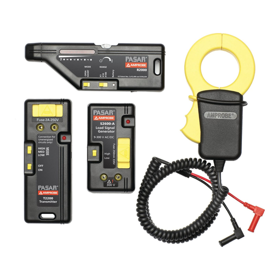
AT-2000-A SERIES PRodUCT dESCRIPTIoN The AT-2000-A System consists of different, yet fully compatible components that are combined into five interchangeable systems: AT-2004-A Industrial Multipurpose Tracer — includes R2000, S2600 -A, T2200, and A2201 Clamp-On Accessory. AT-2005-A Industrial Multipurpose Tracer — includes R2000, S2600 -A, T2200, A2201, B2024, B2025. - Page 8 1. Mode Adjustment Switch ‘open’ mode is used for open conductors. ‘SHORT’ mode is used on conductors that make up a complete circuit. 2. Range Switch Coarse sensitivity adjustment 3. Battery light Will illuminate when unit is turned ‘on’ provided the battery is in place and charged 4.
- Page 9 Using the R2000 Receiver 1. Turn the R2000 ‘ON’ by rotating the thumbwheel and leave it around position ‘5’. 2. Move the range switch to x 1 (this is the least sensitive setting). 3. Place the mode switch into the appropriate position and aim the R2000 properly (see illustration below).
-
Page 10: S2600-A Load Signal Generat Ors (Lsg's)
S2600-A Load Signal Generat ors (LSG’s) When connected to an energized circuit, the LSG’s will rapidly turn themselves on and off. This generates a slight, periodic current fluctuation that causes the power line to emit its own, trace-able signal. this signal can be detected all the way back to the main generator. - Page 11 Both units are intrinsically safe and have a special ‘LOW’ - power setting used when tracing GFCIprotected circuits. As their name implies, when connected to a circuit as a load, the LSG’s cause the power line to generate a signal. The signal will be present anywhere between the LSG and the power source (‘upstream’...
-
Page 12: T2200 Transmitter
task is to identify which 110V breakers control certain receptacles. Use the alligator clip cordset (C2902) for all other applications. 3. Set power switch to ‘High’ when not tracing GFCI-protected circuits. 4. Light will blink if circuit is complete and energized. T2200 Transmitter TThe T2200 injects a signal onto a conductor. - Page 13 1. Intrinsically Safe Fuse Holder Pulling out the fuse holder automatically disconnects the fuse from the circuit while shielding the user from live terminals. 2. Mode Switch ‘High, ‘MED’, and ‘LOW’ voltage setting used to match the impedance of the line.Set at maximum signal level received on wire.
- Page 14 To increase the signal strength, loop the wire around the clamp a few times or use the B2024 Battery Pack. The A2201 will allow wire tracing without the need for direct connection with the bare wire. Using the A2201 Clamp-on transmitter Accessory The A2201 will allow non-contact signal indication into energized or non-energized conductors.
-
Page 15: Application Notes
C2902 ALLIGAT oR- CLIP BANANA PLUG CoRdSET For direct contact to bare conductors APPLICATIoN NoTES Finding opens ‘Opens’ are dead-end conductors that are not connected to anything and therefore do not pass current. To find an open, use the T2200 transmitter, R2000 Receiver, and the alligator clip cordset. -
Page 16: Finding Ground Faults (See Fig.7)
If you end up tracing the entire length of the wire without locating the open, you may be experiencing capacitive coupling, or ‘signal bleed- off’ onto the adjacent conductors. This condition may be alleviated by: a) grounding all adjacent conductors; b) minimizing the distance between the point of connection and the open. -
Page 17: Tracing Wires In Conduit (See Fig.8)
Tracing Wires in Conduit (See Fig.8) When seeking a ground fault within metal conduit, the ‘ground’ is the conduit. Connect the battery to the conduit to complete the circuit. Steel conduit will tend to attenuate the signal strength so tracing will require higher sensitivity levels and access to within a few feet of the conduit. -
Page 18: Tracing Energized Wires
Tracing Energized Wires 1. 1. Connect the alligator clip Cordset to the LSG. 2. Make sure the voltage does not exceed the LSG’s rating. 3. Connect one alligator clip to the hot wire and other to a separate ground (not something that runs along the same path as the hot wire). -
Page 19: Locating Individual Wires In A Bundle
F) Trace the wire - a) In the case of finding shorts, follow the cable path until you lose all the signal. That will be the location of the short. b) In all other cases, follow the wire path to its end. 2. -
Page 20: Locating Outlets From The Breaker Panel (See Fig.10)
B. Non-energized Lines Same procedure as “Tracing Non-energized Lines” except, at the bundle, proceed as in step 6 on previous page. Locating outlets from the Breaker Panel (See Fig.10) If possible, have current flowing in the circuit while tracing. If circuit is not already in use, plug something in to it. -
Page 21: Specifications
SPECIFICATIoNS General operating Temperature: 0 to 120° F (-18°C to 49°C) Storage temperature: -40° to 150° F (-40° to 66°C) Case material: ABS Case size: 11”x15” 1/2” x 4” (39.4 x 27.9 x 10.2 cm) R-2000 Receiver detectors: Electromagnetic coil pickup for short mode. Electrostatic plate pickup for open mode. - Page 22 Fuse: Fast acting 250mA @ 660V (6mm x 32mm) Cat. No. 660.25-6X32 Case: Flame retardant ABS 911 Weight: 3.8 oz (108 grams) T2200 Transmitter operating Frequency: 32.768 KHz duty Cycle: Transmits 2 pulses with a duration of 0.0625 each every 0.5 seconds.
- Page 23 B2024 Battery Pack Type: Nickel-Cadmium Rechargeable (20AA cells) Capacity: 24Volt, 600 mah Recharge Time: 14 hours Fuse: Internal self-resetting B2025 Recharger/Converter Input: 115VAC output: 24VDC @ 350 mah...
- Page 24 Figure 1. Strong Signal Correct Orientation to wire. Weak Signal Incorrect Orientation to Wire Strong Signal Turn Receiver to Proper Orientation Figure 2. In the ‘SHoRT ‘ mode, orient Receiver so that is perpendicular to the wire. Example: Horizontal wire — thumbwheel should face up; Vertical wire —...
- Page 25 R2000 No Signal Signal Panel To transformer C2902 Cord Figure 3. R2000 Signals Cancel R2901 Cord Set Figure 4.
- Page 26 Tracing Buried Cables To Power Source Figure 5. R2000 T2200 Signal No Signal Break Tracing Open Wire Figure 6.
- Page 27 Figure 7. Ground Fault R2000 Figure 8. identifying circuit Breakers Ground S2600-A Neutral Figure 9. Short to Ground R2000...
- Page 28 To Outlets and Equipment T2200 A2201 B2024 Figure 10. Tracing Downstream Loads Figure 11. Tracing Buried Conduit B2024 T2200 A2201...
- Page 30 Visit www.Amprobe.com for • Catalog • Application notes • Product specifications • User manuals Amprobe ® www.Amprobe.com info@amprobe.com Everett, WA 98203 Tel: 877-AMPROBE (267-7623) Amprobe Europe ® Beha-Amprobe In den Engematten 14 79286 Glottertal, Germany Please Tel.: +49 (0) 7684 8009 - 0...
Need help?
Do you have a question about the AT-2004-A and is the answer not in the manual?
Questions and answers