Table of Contents
Advertisement
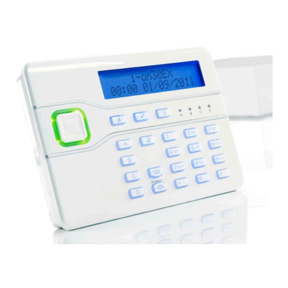
Quick Links
Advertisement
Table of Contents

Related Manuals for Cooper Security i-on30EX


Summary of Contents for Cooper Security i-on30EX
- Page 2 Printed and published in the U.K. This manual applies to the i-on30EX and i-on30EXD control units with version 3 software. For Your Safety This book contains several passages alerting you to potential problems or hazards. Each of these are marked by the words Note, Caution or WARNING.:...
-
Page 3: Table Of Contents
CONTENTS Connecting the Telephone Line ..18 Fit ADSL Filter ........ 18 Step 9. Fit a Plug-By Communicator ..19 1. Introduction ........1 Step 10. Fit and Connect Battery ..20 Communications ........1 Step 11. Initial Power-Up ......20 Level Setting or Partitioned System .. - Page 4 This page is intentionally blank. Page iv...
-
Page 5: Introduction
ID. This module also allows 1. Introduction remote maintenance. i-dig02 A PSTN module that allows the The i-on30EX is a control unit for a hybrid control unit to report alarm wired/wirefree alarm system intended for (ATS2) information using standard commercial or large domestic use. -
Page 6: Installer Programming Interface
If you wish, you can also connect a PC or signals from their detectors successfully. laptop to the USB port on the control unit pcb and use Cooper Security‟s Downloader To do this you should conduct signal software to program the control unit. -
Page 7: Guided Tour
Guided Tour CAUTION: All printed circuit boards for the i-on30EX, its expanders and keypads have been tested for Electromagnetic Compatibility (EMC). However, when handling the pcbs you must take the standard precautions for handling static sensitive devices. - Page 8 1. Case back. 2. Fixing holes. 3. Cable entry holes for zone and bus wiring. 4. Transformer. 5. Mains fuse and connector block. 6. Mains cable anchor point. 7. Cable entry hole for mains. 8. Printed circuit board (PCB).
- Page 9 1. Built-in communicator telephone line connector. (i-on30EXD only.) 2. Siren and strobe. 3. Loudspeaker. 4. Bus cable connector. 5. Output (transistorised). 6. Aux power. 7. Wired zone connectors. Figure 3 Control Unit Main Connectors Page 5...
-
Page 10: Keypad Controls And Displays
Keypad Controls and Displays Figure 6 Keypad Rear Housing Figure 4 Controls and Displays 1. Central keyhole. 1. LCD display (2 x 20 characters). 2. Rear tamper shroud. 2. Programming keys. 3. Cable entry. 3. Navigation keys 4. Fixing holes. - Page 11 1. Cable entry. 2. Fixing holes. 3. Addressing button. 4. Bus cable connector. 5. Central keyhole. 6. Outputs. 7. Aux power. 8. Lid tamper. 9. Bus address display. 10. Zone connectors. 11. Sounder. 12. Bus termination jumper. 13. Engineering keypad connector Figure 8 Wired Expander 1.
-
Page 12: Power Availability
Power Availability Note: All current drawn from the Aux terminals (12V) must be included in the overall calculation. Before connecting any external devices to the control unit, you must make sure that CAUTION: Ensure that the system does not... -
Page 13: Cable Configuration And Length
Bus Termination each cable is more than 10m then DO NOT fit the termination jumpers on any The i-on30EX bus uses the RS485 interface. of the devices. Because of this the ends of the line in some configurations may be terminated to... - Page 14 Reducing Voltage Drop - Method 2: the bus, otherwise an earth fault will occur. Supply the detection devices from the Aux Cooper Security recommend the EXP-PSU. output on separate cores. This is the When installing a remote power supply, fit preferred method of reducing voltage drop it close to the equipment it is powering.
-
Page 15: Installation
Where the cable run from the control 3. Installation unit will be longer than 100m (see Cable Configuration and Length). Note: The installation steps listed below Note: Do not site two or more keypads assume that you have already decided on... -
Page 16: Tone Volume
The jumpers have the following functions: on Figure 2) or any of the expanders (see 13 on Figure 8 or 10 on Figure 9). An Engineering Keypad does not need to be ABCD-ON addressed, and will always be recognised by the control unit. -
Page 17: Step 5. Connect Control Unit To Mains
Each loudspeaker draws up to 280mA in different on the expander compared to the operation. if there is more than one control unit. expander loudspeaker then the bus may not be able to supply sufficient current during an alarm. -
Page 18: Shock Sensors And Roller Shutter Sensors
When programming select the FSL resistor values for the control unit in Installer Menu - System Options - Wired Zone Type. To select the resistor values for a wired expander use Installer Menu – Detectors Devices – Wired Expanders - Edit Expander. -
Page 19: Step 7. Connect Wired Outputs
Wired Outputs on Expanders as 2-wire FSL, with 2k2/4k7 resistors. See Each EXP-W10 wired expander provides i-on Range Engineering Guide part number connections for up to four transistor driven 12098019 for more details. -
Page 20: Remote Loudspeakers (Optional)
Figure 25 shows a general method of using For FSL wiring, connect a 2k2 resistor in the outputs on a wired expander to connect series with the link from –TR on the a wired external sounder. external sounder to the left hand terminal of the zone connector see Figure 27. -
Page 21: Step 8. Connect The Internal Communicator (I-On30Exd Only)
Step 8. Connect the Statutory Information Internal Communicator Applications The built-in communicator is suitable for (i-on30EXD only) connection to the following types of networks: The i-on30EXD version of the control unit has an internal communicator on its main (a) Direct exchange lines (PSTN) supporting PCB. -
Page 22: Safety Notice
Fit ADSL Filter If the telephone line is being shared by a broadband service then you should fit a broadband filter to the line. Cooper Security provide the ADSL01 filter that plugs onto TNV - Telephone line connector. pins provided for the purpose on the main SELV –... -
Page 23: Step 9. Fit A Plug-By Communicator
Figure 31 Plug-By Communicator Wiring Note: Comms O/P4 will be active when the system is unset. This is normal. To fit a communicator, follow the instructions below. Caution: Follow the instructions in the order shown, or you may damage the control unit and/or communicator. -
Page 24: Step 10. Fit And Connect Battery
Line Monitoring for a Dual-Path Note: Connecting the battery without mains Communicator power will not start the system. (See If a standalone dual-path (landline and “Programming Before Installation” in the i- mobile) communication device, such as a on Range Engineering Guide.) RedCARE STU, is connected to the plug-by Step 11. - Page 25 4. Press or to show other countries, make subsequent programming easier. for example The control unit assigns the next free bus address to a bus device when you make the device request a bus address. ...
-
Page 26: Leaving The Installer Menu
Leaving the Installer Menu Note: If you attempt to leave the Installer Menu when a detector tamper is active then If you wish to leave the Installer Menu at the keypad displays a fault message telling any time. you which detector is causing the problem. -
Page 27: Defaulting Access Codes
As you start to key in the code the 4. Short the Reset Codes pins together display shows: using a screwdriver or jumper link. (Keep the short on until step 6.) 5. Apply mains power. When you key in the last digit of the... -
Page 28: Step 12. Commission The System
6. Press . Program the system to suit user requirements. Page 25 is a summary of the The display shows: Installer Menu on the i-on30EX. Please see the i-on Range Engineering Guide for a more detailed description. -
Page 29: Installer Menu
Installer Menu Settle time Zone alarms 1 DETECTORS/ Exit time Zone tampers Call Mode DEVICES Entry time System tampers Messages Detectors Siren delay DD243 Phone Book Add/Del Detectors Siren time Confirmation Triggers Program Zones Strobe on Set Confirmation time... - Page 30 Appears only in a Partitioned system (or when zones have a type other than “Not Used”). Appears only in a Level Setting system. Appears only when Report Type=Fast Format Appears when Report Type=CID or SIA Options visible depend on communications module fitted, or if using i-on30EXD.
-
Page 31: Maintenance
Check the condition of the control unit Product 30 zone hybrid endstation standby battery. Description with remote keypads. Check the cabling to the keypad(s) and Manufacturer Cooper Security Ltd. expander(s) for signs of damage or Environmental Class II. wear. Operating Tested -10 to +55°C. temperature... -
Page 32: Security
You can connect any EN50131-6 ratings combination of these devices to the bus. The i-on30EX provides space for one 7Ah 2. The system can be used as EITHER a battery. partitioned system OR a part setting system. -
Page 33: Electromagnetic Compatibility
The control unit has a replaceable T250mA mains fuse. Electrical Safety Conforms to EN60950-1. Other If you wish to connect the i-on30EX control unit to a PC using the USB port then make sure that the cables have the following specifications: Mini-B plug for control unit end, USB-A for PC end. -
Page 34: Compatible Equipment
Compatible Equipment 706rEUR-00 Two button PA/tilt switch i-kp01 Keypad for i-on30EX transmitter systems when containing keypad s/w v2.0. NOTE: 710rEUR-00 Two button PA use only those keypads 713rEUR-00 Pet tolerant PIR bearing the “i-onEX ” compatibility label. 714rEUR-00 PIR Transmitter (Small... - Page 35 NOTES: Page 31...
- Page 36 Product Support (UK) Tel: +44 (0) 1594 541979. Available between: 08: 30 to 17:00 Monday to Friday. Product Support Fax: (01594) 545401 email: techsupport@coopersecurity.co.uk Part Number 12126081 11/8/2011 Page 32...
Need help?
Do you have a question about the i-on30EX and is the answer not in the manual?
Questions and answers