Table of Contents
Advertisement
Advertisement
Table of Contents

Related Manuals for Cooper Security 9651PD


Summary of Contents for Cooper Security 9651PD
- Page 1 ALARM SYSTEM USER GUIDE Issue 3...
-
Page 2: Table Of Contents
Aborting False Alarms .... 10 Your Installation ......28 3. After an Alarm ......11 9651PD Hardwired Control Unit Alarm System User Guide. This document applies to control panels using software version 6.x. © Cooper Security Ltd. 2012 IN NO EVENT WILL COOPER BE LIABLE FOR ANY SPECIAL, CONSEQUENTIAL , OR INDIRECT LOSS OR... -
Page 3: Compliance Statements
Compliance Statements The 9651PD control unit is compliant with EN50130-5 environmental class II. The 9651PD control unit is suitable for use in systems designed to comply with PD 6662: 2010 at Grade 2X. The 9941 and 9943 keypads are suitable for use in systems designed to comply with PD 6662;2010 at Grade 2. - Page 4 This page is deliberately blank. Page iv...
-
Page 5: Introduction
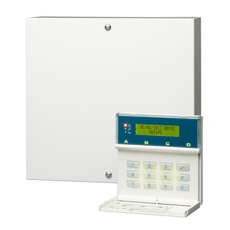
Alarm System The alarm systems described in this book comprise a control unit (model 9651PD), one or more keypads, and various detectors. The control unit houses a main controller, power supply, stand-by battery and communication device. It is normally fitted in a safe place out of sight (for example, under the stairs). -
Page 6: Keypad
1. Introduction Keypad Your alarm system is fitted with a 9941 or 9943 keypad, from which you can set and unset the system. Figure 1 shows the main features of the keypad. Refer to "4. Special Functions" on page 12 for information about other functions available from the keypad. - Page 7 1. Introduction These may show nothing until a user is identified. Alert lamp (see page 12) Service lamp Mains lamp Flashes to highlight Glows if the Glows when unacknowledged alarm, system needs using mains fault or tamper conditions. an Installer power.
-
Page 8: Mains Power Failures
1. Introduction Mains Power Failures The control unit indicates mains power failures using alerts. If the supply has since been restored, the alert will show the condition as inactive. For instructions on how to view and acknowledge alerts, refer to page 12. About this Guide The rest of this guide tells you how to use the system: 2. -
Page 9: Everyday Operation
2. Everyday Operation During installation, your installer programs the system to create an exit route and entry route for your premises. When setting the system, you must follow the exit route. When unsetting the system, you must follow the entry route. If you stray from these routes, you may cause a false alarm. -
Page 10: General Procedure
Leave by the designated exit route. When you complete the exit procedure in Set A accordance with the setting method in use, 9651PD the system sets and gives a double "beep". Set A The keypad display shows which level or 9651PD partition is set. -
Page 11: Timed Set
2. Everyday Operation Timed Set With Timed Set, the system sets after a programmed exit time has expired. The time starts when you press a level key, or when you press to accept an omitted zone. Your installer will have made the exit time long enough for you to leave the premises and secure the final door Final Door Set Your installer may have programmed the system so that closing the final door... -
Page 12: Investigating Setting Problems
2. Everyday Operation Investigating Setting Problems This section offers general guidance but the configurable nature of 9651PD control units means that details of each alert and response vary. If you need assistance to resolve a problem, contact your installer. Detector Active If something is triggering a detector at the end of the exit procedure, the system will not set. - Page 13 2. Everyday Operation call an installer to do this for you (see page 11). If the display shows "Set" underneath the alert message, press to continue with setting. If an installer reset is required, the control unit lights the lamp and the keypad sounds a repeating "beep"...
-
Page 14: Unsetting The System
As you enter the premises, the system Entry starts the entry timer and the keypads 9651PD give the entry tone. The display shows the level you entered (for example): Key in an access code (or present a tag). -
Page 15: After An Alarm
Responding to a Fire Alarm IMPORTANT: The system gives a fire alarm by Fire Z02 Alarm sounding a two-tone warning from the keypads and 9651PD alarm sounder. The display shows (for example): Evacuate the premises. Do not attempt to unset the alarm. -
Page 16: Special Functions
4. Special Functions Introduction As well as setting and unsetting the system, you can perform a number of other functions from the keypad while the system is unset: All Users Description Access code (or tag) View alerts plus: Omit zones Require user code before installer code Change own user code Read the log of system events... -
Page 17: Key 2: Omitting Zones
If you have viewed all alerts and installer action is Call Installer required (for example, to fit a new battery), the 9651PD display shows: In this case, contact your alarm company. If you have viewed all alerts and no installer action... -
Page 18: Key 3: Requiring User Code Before Installer Code
4. Special Functions Press the number of the zone you want to omit (for example, press 07 to omit zone 7) and then press . The sounder gives a double "beep" and Omit Zone 07o the display shows the zone number followed by an "o": If you try to omit a zone for which this is Omit Zone 07X... -
Page 19: Key 4: To Change An Access Code
4. Special Functions Key 4: To Change an Access Code Note: Cooper Security advise you to ensure that each user has their own access code, and no one user (including the master user) knows any other user’s access code. Key in the access code that you wish to change. -
Page 20: Key 7: Turning The Chime On And Off
4. Special Functions In the log, user codes are represented by numbers as follows: Installer User 1 U02 to 50 Users 2 to 50 Control unit Remote reset Key 7: Turning the Chime On and Off Your system may be programmed so that a chime tone sounds when certain doors are opened while the system is unset. -
Page 21: Key 9: Testing Detectors
4. Special Functions Key 9: Testing Detectors You can set the system so that it will allow you to walk around and test each of the detectors (a walk test). Do this when the premises are empty to avoid other people triggering movement detectors before you do, which would confuse the results of the test. - Page 22 4. Special Functions The default access code for all users U02 through to U50 is “0000”. As default codes cannot be used to set or unset the system, or use any of its special functions, they do not need to be changed until they are assigned to users. Note: Once a master user assigns a code to another user, they must instruct the user to change their code straight away to something that the master user does not know.
- Page 23 4. Special Functions If you wish to change the name, use the keypad as described in Changing User Names on page 19. Go to step 6. If you do not want to change the name, then press . User 21: ---- The display shows (for example): Key in the new access code.
- Page 24 U21:User 21 number of the code you want to add a tag to, for example: Press . User 21: ---- The display shows (for example): Present an unused tag to the front of the keypad. 30/07/2012 14:45 9651PD Page 20...
- Page 25 Present the tag you wish to delete to the front of the keypad. The display shows, for example: Key in “0000” 30/07/2012 14:45 9651PD The keypad gives a double beep confirmation tone and then displays the time and date: Page 21...
-
Page 26: Key 6: Setting Time And Date
The display shows the time. H17 M02 Key in two digits for the hour followed by . Use the 24-hour clock. Key in two digits for the minutes, followed by . The display shows the new time and date: 30/07/2012 14:45 9651PD Page 22... -
Page 27: Appendix. Log Messages
Appendix. Log Messages Message Meaning Message Meaning Mains power supply AC Fail Fire Z== Alarm Fire alarm on zone == failed Fire Z== Rstr Fire alarm on zone == AC Restore Mains power supply restore restored Fr K== Alarm Fire alarm started at Al Conf Dis K== Alarm confirmation keypad ==... - Page 28 Appendix Message Meaning Message Meaning Tech Z== Alarm Technical alarm in zone Z== Lock Out The system locked out the zone when attempting to rearm at Tech Z== Rstr Technical alarm in zone the end of the bell run == reset time.
- Page 29 NOTES: Page 25...
- Page 30 NOTES: Page 26...
- Page 31 NOTES: Page 27...
-
Page 32: Your Installation
Your Installation Zone Description Omit Chime Allow Company Name Contact Number (Day) Control Unit Model Contact Number (Night) Exit Time Bell Duration Entry time Communicator Fitted Note: If this table has not been completed, ask your Installer for the information. Page 28...
Need help?
Do you have a question about the 9651PD and is the answer not in the manual?
Questions and answers