Table of Contents
Advertisement
Quick Links
Advertisement
Table of Contents
Troubleshooting

Related Manuals for OutBack Power Radian International Series


Summary of Contents for OutBack Power Radian International Series
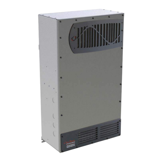
- Page 1 Radian International Series Inverter/Charger GS3548E GS7048E Operator’s Manual...
- Page 2 Radian International Series Inverter/Charger Operator’s Manual © 2012 by OutBack Power. All Rights Reserved. Trademarks OutBack Power and the OutBack Power logo are trademarks owned and used by OutBack Power, an EnerSys company. These trademarks may be registered in the United States and other countries. Date and Revision...
-
Page 3: Table Of Contents
Table of Contents Introduction ..................7 Audience ........................... 7 Symbols Used ........................... 7 General Safety .......................... 7 Welcome to OutBack Power ....................8 Inverter Functions ........................9 GS7048E ............................10 GS3548E ............................10 Inverter Controls ........................10 ... - Page 4 Table of Contents Troubleshooting ................. 45 Basic Troubleshooting ......................45 Module Select ............................. 50 Error Messages ........................51 Warning Messages ......................... 52 Temperature Events ........................... 53 GT Warnings ............................53 Disconnect Messages ......................54 Sell Status ..........................55 Specifications ..................
- Page 5 Radian Menu Items ..................63 Table 18 Terms and Definitions ................. 68 List of Figures Figure 1 Radian International Series Inverter/Charger ..........8 Figure 2 Charging Stages Over Time ................ 28 Figure 3 Charging Stages Over Time (24/7) ..............
- Page 6 Table of Contents THIS PAGE INTENTIONALLY LEFT BLANK. 900-0145-01-02 Rev A...
-
Page 7: Introduction
When this symbol appears next to text, it means that more information is available in other manuals relating to the subject. The most common reference is to the Radian International Series Inverter/Charger Installation Manual. Another common reference is the system display manual. -
Page 8: Welcome To Outback Power
Introduction Welcome to OutBack Power Thank you for purchasing the OutBack Radian International Series Inverter/Charger. It is designed to offer a complete power conversion system between batteries and AC power. As part of an OutBack Grid/Hybrid™ system, it can provide off-grid power, grid backup power, or grid-interactive service which sells excess renewable energy back to the utility. -
Page 9: Inverter Functions
This product has a settable AC output range. In this book, many references to the output refer to the entire range. However, some references are made to 230 Vac or 50 Hz output. These are intended as examples only. Outback Power Technologies Intuitive Control System for Renewable Energy 900-0145-01-02 Rev A... -
Page 10: Gs7048E
(See page 63 for default settings.) However, certain products can monitor, operate, or program the Radian. These include OPTICS RE and the MATE3 class of system display. See the Radian International Series Inverter/Charger Installation Manual for information on wiring a manual on/off switch. -
Page 11: Operation
Operation Inverter Functionality The Radian inverter can be used for many applications. Some of the inverter’s operations occur automatically. Others are conditional or must be enabled manually before they will operate. Most of the inverter’s individual operations and functions can be programmed using the system display. -
Page 12: Generator
Operation NOTE: The input terminals are labeled for grid and generator due to common conventions, not because of inverter requirements. Each input can accept any AC source as long as it meets the requirements of the Radian inverter and the selected input mode. If necessary, the G terminals can accept grid power. -
Page 13: Support
Operation Support The Support mode is intended for systems that use the utility grid or a generator. In some cases the amount of current available from the source is limited due to size, wiring, or other reasons. If large loads are required, the Radian inverter augments (supports) the AC source. The inverter uses battery power and additional sources to ensure that the loads receive the power they demand. -
Page 14: Grid Tied
Operation Grid Tied IMPORTANT: Selling power to the utility company requires the authorization of the local electric jurisdiction. How the utility company accommodates this will depend on their policies on the issue. Some may pay for power sold; others may issue credit. Some policies may prohibit the use of this mode altogether. -
Page 15: Grid Interface Protection Menu
Operation Grid Interface Protection Menu Grid-interactive requirements vary in different locations around the world. The grid-interactive settings are adjustable in the Grid Interface Protection and Grid Support menus. These menus are only available with installer-level access. These settings are generally controlled by the local authorities or interconnection agreement and should not be altered by the end user. -
Page 16: Ups
Operation Failure In UPS mode, the Radian’s parameters have been optimized to reduce the response time. If the utility grid becomes unstable or is interrupted, the Radian can transfer to inverting with the fastest possible response time. This allows the system to support sensitive AC loads without interruption. - Page 17 Operation If the inverter is connected to the grid and the charger is turned off, another source such as renewable energy should be present to charge the batteries. The inverter will observe the batteries as if it was charging. When the batteries reach the required voltage and time to end the cycle, the inverter will disconnect from the grid.
-
Page 18: Gridzero
Operation GridZero In GridZero mode, the Radian inverter remains grid-connected, but prioritizes the use of battery or renewable sources to run loads. It uses only renewable energy to recharge the batteries. The inverter tries to “zero” the grid use, drawing on AC power only when needed to supplement stored DC sources. -
Page 19: Table 1 Summary Of Input Modes
Operation Table 1 Summary of Input Modes Mode Summary Benefits Cautions Intended Charger Accepts power Can use AC that may be Will pass irregular or Source: Performs three-stage from an unusable in other modes low-quality power to the Generator charge and goes irregular or... - Page 20 Operation NOTES: 900-0145-01-02 Rev A...
-
Page 21: Description Of Inverter Operations
Operation Description of Inverter Operations The items in this section are operations common to all Radian inverters. These are used in most or all of the input modes described in the preceding section. Some of the items in this section are functions which can be manually selected, enabled, or customized. -
Page 22: Ac Frequency
Operation Low Battery Cut-In: The recovery point from Low Battery Cut-Out. When the DC voltage rises above this point for 1 minute, the error will clear and the inverter will resume functioning. Connecting an AC source for the inverter to charge the batteries will also clear a low battery error. High Battery Cut-Out: If the DC voltage rises above this limit for 1 second (default), the inverter will stop functioning. -
Page 23: Input
Operation Search mode sensitivity is adjusted with the Sensitivity menu item. See Table 17, which begins on page 63, for the location of this item. The sensitivity is adjusted in small increments which are measured in fractions of one ampere. NOTE : Increment sizes are difficult to define due to varying load characteristics. -
Page 24: Ac Current Settings
Operation Two sets of AC input terminals are available. Both inputs are identical and can be used for any AC source. However, for easy reference, the first input has been labeled G (for the utility grid). The second input is labeled G (for a generator). -
Page 25: Generator Input
Operation When these conditions are met, the inverter will close its transfer relay and accept the input source. This occurs after a delay which is specified below. If the conditions are not met, the inverter will not accept the source. If it was previously accepted and then rejected, the inverter will open the relay and return to inverting power from the batteries. -
Page 26: Transfer
Operation Transfer The inverter uses a transfer relay to alternate between the states of inverting and of accepting an AC source. Until the relay energizes, the output terminals are electrically isolated from the input that is in use. When it closes, the input and output terminals become electrically common. (The terminals for the unused input remain isolated during this time.) When the relay changes states, the physical transfer delay is approximately 25 milliseconds. -
Page 27: Battery Charging
Operation Battery Charging IMPORTANT: Battery charger settings need to be correct for a given battery type. Always follow battery manufacturer recommendations. Making incorrect settings, or leaving them at factory default settings, may cause the batteries to be undercharged or overcharged. Charge Current Batteries or battery banks usually have a recommended limit on the maximum current used for charging. -
Page 28: Charge Cycle
Operation Limiting Charge Current (Multiple Inverters) It is not advisable to set Charger AC Limit less than 12 Aac in a stacked system. The Power Save function requires the master inverter to activates the slave chargers in sequence only when the charge current exceeds 11 Aac. If the setting is less than 12, Power Save will not activate any other chargers. -
Page 29: Advanced Battery Technologies
Operation Advanced Battery Technologies Advanced battery technologies such as lithium-ion and sodium-sulfur may require very different settings from the inverter’s defaults or the three-stage cycle in general. The Charging Steps section describes the individual selections and behavior. All charger settings are adjustable for different priorities. - Page 30 Operation Time limit: Absorb Time setting. The charger does not necessarily run through its full duration if it retained time from a previous cycle. The timer counts down from the inception of Absorption stage until it reaches zero. The time remaining can be viewed in the system display. The Absorption timer does not reset to its maximum amount, or to zero, when AC power is disconnected or reconnected.
-
Page 31: New Charging Cycle
Operation Time limit: Float Time setting. The charger will go Silent once the timer has expired (if another stage is not still in progress.) The Float timer is reset to its maximum amount whenever the batteries decrease to the Re-Float Voltage setting. NOTE : The Float timer begins running any time the battery voltage exceeds the Float Voltage set point. - Page 32 Operation Voltage Cycle 1 Cycle 2 AC Loss Refloat Absorption Silent Refloat Float Float Silent Absorption Set Point Float Set Point Re-Float Set Point Absorption Float timer Float timer runs Float timer runs timer runs Time resets (part) Inverter now charging to a new Inverter completed charging;...
- Page 33 Operation Cycle 3 Cycle 5 Cycle 4 AC Loss AC Loss AC Loss Bulk Abs. Bulk Absorption Silent Bulk Absorption Silent Absorption Set Point Float Set Point Re-Bulk Set Point Absorption Absorption Absorption Absorption Absorption timer resets timer runs timer runs timer timer runs (part)
-
Page 34: Equalization
Operation Equalization Equalization is a controlled overcharge that is part of regular battery maintenance. Equalization brings the batteries to a much higher voltage than usual and maintains this high voltage for a period of time. This has the result of removing inert lead sulfate compounds from the battery plates. - Page 35 Operation If installed in a system networked with a HUB Communications Manager, only a single RTS is necessary. In most cases the RTS must be plugged into the master inverter. A system display must be present for the compensation values to be shared to all devices. NOTE : In the FLEXmax 100 or FLEXmax Extreme charge controller, the rate of compensation is adjustable.
-
Page 36: Offset
Operation Offset Offset is an automatic operation which occurs in certain conditions. It is not a programmable inverter function. This operation uses excess battery energy to power the loads when an AC source is present. The system can take advantage of renewable energy sources, “offsetting” dependence on the AC source. -
Page 37: Grid Support
Operation Grid Support Grid Support functionality helps the Radian comply with requirements imposed by utility companies. This functionality is only available in the Grid Tied and GridZero input modes. When either mode is selected, the settings within the Grid Support menus are active. If local jurisdiction requires grid support functionality, some or all of the advanced functions may be required. -
Page 38: Figure 6 Grid Support Function Screen
Operation The settings for each item will vary depending on the standards being applied. Not all functions are enabled. When a particular standard is applied, the settings will be pre-loaded accordingly. The screen in Figure 6 shows which functions are enabled. Figure 6 Grid Support Function Screen When Grid Support functions require the inverter to export power to help sustain grid voltage or... -
Page 39: Auxiliary Terminals
Operation Auxiliary Terminals The Radian inverter has two sets of terminals that respond to different criteria to control certain operations. The 12V A terminals provide a 12 Vdc output that can deliver up to 0.7 Adc to control external loads. The R terminals are “dry”... - Page 40 (This is illustrated in the Radian International Series Inverter/Charger Installation Manual.) When the voltage falls below this set point for a settable delay period, the A output turns off.
- Page 41 Operation allows current to flow from the batteries to a dedicated DC load. (This is illustrated in the Radian International Series Inverter/Charger Installation Manual.) The resistor or load must be sized to dissipate all of the energy from the renewable source if necessary. Diversion will turn off following a delay when a low DC voltage setting is reached.
-
Page 42: Table 4 Aux Mode Functions
Operation Table 4 AUX Mode Functions Triggers Name Purpose Settable Points Start Stop Operates designated High Vdc Low Vdc Low & high Vdc Load loads normally; turns off High temp On & Off delay Shed loads in severe conditions Low output Vac ... -
Page 43: Metering
Metering MATE3-Class System Display Screens A MATE3-class system display can monitor the inverter and other networked devices. From the Home screen, the < Inverter > “soft” key accesses the inverter monitoring screens. 52.0 V 231 V Inverter Soft Key Figure 7 Home Screen Inverter Screens The Inverter soft key opens a series of screens showing the inverter operating mode, battery... -
Page 44: Battery Screen
Metering Charge displays the kilowatts and AC amperage consumed for the inverter to charge the battery bank. This line also shows the present charging stage. Load displays kilowatts and AC amperage consumed by devices on the inverter’s output. It can be the same as Invert. -
Page 45: Troubleshooting
Troubleshooting Basic Troubleshooting Table 5 is organized in order of common symptoms, with a series of possible causes. Each shows possible troubleshooting remedies, including system display checks where appropriate. Metal pads are located at these locations. In troubleshooting, AC voltages can be measured at this series of test points. - Page 46 Troubleshooting Table 5 Troubleshooting Symptom Possible Cause Possible Remedy One or more units Unit is slave and is in Silent System display only: Check Power Save Levels in the have no output but mode. Inverter Stacking menu and test with loads. Determine if the others do (in multi- inverter comes on at the appropriate levels.
- Page 47 Troubleshooting Table 5 Troubleshooting Symptom Possible Cause Possible Remedy Charge complete or nearly Check the DC voltage and charging stage using the system complete. display, if present. Confirm with DC voltmeter. System display DC meter Check the DC voltage on the inverter’s DC terminals. If reads significantly higher than different from the system display reading, the inverter could actual battery voltage.
- Page 48 Troubleshooting Table 5 Troubleshooting Symptom Possible Cause Possible Remedy Test the L and N test points with an AC voltmeter. (See Unusual voltage System neutral and ground on hot or neutral may not be bonded. page 45.) These measurements should give full voltage. output line.
- Page 49 Troubleshooting Table 5 Troubleshooting Symptom Possible Cause Possible Remedy Inverter’s output has been Disconnect the wires from the inverter’s AC input or AC connected to its input. output terminals, or both. If the problem immediately disappears, it is an external wiring issue. The inverter’s AC I Voltage shifts are the result of and AC O must remain isolated from each other.
-
Page 50: Module Select
Troubleshooting Table 5 Troubleshooting Symptom Possible Cause Possible Remedy The inverter’s G input is in If the input priority is set to GRID and the G terminals are AGS or Gen Alert functions start the use and the input priority is energized, an automatically controlled generator will shut set to GRID. -
Page 51: Error Messages
Troubleshooting Error Messages An error is caused by a critical fault. In most cases when this occurs, the unit will shut down. A MATE3-class system display will show an event and a specific error message. This screen is viewed using the Home screen’s soft keys. (See the system display literature for more instructions.) One or more messages will display Y (yes). -
Page 52: Warning Messages
Troubleshooting Warning Messages A warning message is caused by a non-critical fault. When this occurs, the unit will not shut down, but a MATE3-class system display will show an event and a specific warning message. This screen is viewed using the Home screen’s soft keys. (See the system display literature for more instructions.) One or more messages will display Y (yes). -
Page 53: Temperature Events
Troubleshooting Table 7 Warning Troubleshooting Message Definition Possible Remedy The inverter’s internal cooling fan is not Turn the battery disconnect off, and then on, to Fan Failure operating properly. Lack of cooling may determine if the fan self-tests. If it does not, result in derated inverter output wattage. -
Page 54: Disconnect Messages
Troubleshooting Disconnect Messages Disconnect messages explain why the inverter has disconnected from an AC source after previously being connected. The unit returns to inverting mode if turned on. The Last AC Disconnect screen is viewed using the AC INPUT hot key on a MATE3-class system display. One or more messages will display Y (yes). -
Page 55: Sell Status
Troubleshooting Sell Status Sell Status messages describe conditions relating to the inverter’s grid-interactive mode. This screen is viewed using the Home screen’s soft keys on a MATE3-class system display. (See the system display literature for more instructions.) One or more messages will display Y (yes). If a message says N (no), it is not the cause of the disconnection. - Page 56 Troubleshooting NOTES: 900-0145-01-02 Rev A...
-
Page 57: Specifications
Specifications Electrical Specifications NOTE : Items qualified with “default” can be manually changed using the system display. Table 12 Electrical Specifications for Radian Models Specification GS7048E GS3548E Continuous Output Power at 25°C 7000 VA 3500 VA Continuous AC Output Current at 25°C 30.4 Aac 15.2 Aac AC Output Voltage (default) -
Page 58: Mechanical Specifications
Specifications Table 12 Electrical Specifications for Radian Models Specification GS7048E GS3548E DC Input Power (continuous) 7.634 kVA 3.817 kVA DC Input Max. Current (continuous full power) 175 Adc 87.5 Adc DC Input Maximum Current (surge) 406.5 Adc 203.3 Adc DC Input Maximum Current (short-circuit) 8975 Adc 4488 Adc Battery Charger Maximum AC Input... -
Page 59: Environmental Specifications
Specifications Environmental Specifications Table 14 Environmental Specifications for Radian Models Specification Value Rated Temperature Range (meets component specifications; however, –20°C to 50°C ( –4°F to 122°F) please note that the inverter output wattage is derated above 25°C) Operational Temperature Range (functions, but not rated for operation; –40°C to 60°C (–40°F to 140°F) does not necessarily meet all component specifications) –40°C to 60°C (–40°F to 140°F) -
Page 60: Regulatory Specifications
Specifications Regulatory Specifications Certifications The Radian GS3548E and GS7048E are certified to the following standards: This product has been ETL certified to meet the following standards: IEC 62109-1:2010 and IEC 62109-2:2011 — Safety of Power Converters for use in Photovoltaic Systems (2010) IEC 62477-1:2012 —... -
Page 61: Limiting Charge Current (Multiple Inverters)
11 Aac. If the setting is less than 12, Power Save will not activate any other chargers. For more information on this function, see the Power Save section of the Radian International Series Inverter/Charger Installation Manual. When the Charger AC Limit setting is 12 Aac or more, other active chargers add the same amount to the total. -
Page 62: Table 15 Chargers On And Current Settings
Specifications To calculate the chargers and settings Table 15 Chargers On (as described on the previous page): and Current Settings NOTE : Table 15 consists of pre-calculated values and is GS3548E GS7048E not used in this calculation. However, for comparison, the Charge items used in this calculation have been marked in the table. -
Page 63: Firmware Revision
Specifications Firmware Revision This manual applies to Radian inverter models GS7048E and GS3548E with revision 001.006.065 or higher. Updates to the Radian’s firmware are periodically available. These can be downloaded from the OutBack website www.outbackpower.com or www.alpha-outback-energy.com. To upgrade a Radian inverter to firmware revision 001.006.063 or higher, the following is required: A MATE3s system display with revision 001.001.000 or higher. - Page 64 Specifications Table 17 Radian Menu Items Field Item Default Minimum Maximum Generator, Support, Grid Tied, UPS, Input Mode Generator Backup, Mini Grid, GridZero 208 Vac 170 Vac 230 Vac Lower Voltage Limit 252 Vac 232 Vac 290 Vac Upper 1.0 second 0.12 seconds 4.0 seconds Transfer Delay...
- Page 65 Specifications Table 17 Radian Menu Items Field Item Default Minimum Maximum Off, Auto or On Aux Control Auto Load Shed, Gen Alert, Fault, Vent Fan, Gen Alert Aux Mode Cool Fan, DC Divert, GT Limits, Source Status, AC Divert Auxiliary (Load Shed) ON: Batt >...
- Page 66 Specifications Table 17 Radian Menu Items Field Item Default Minimum Maximum Volts 288 Vac 240 Vac 288 Vac Mode Cont. Cont., Mand., Perm., Mom., Cease 0.16 seconds 0.12 seconds 5.00 seconds Trip Volts 264 Vac 240 Vac 280 Vac Mode Cont.
- Page 67 Specifications Table 17 Radian Menu Items Field Item Default Minimum Maximum 212 Vac 196 Vac 248 Vac 228 Vac 212 Vac 252 Vac 252 Vac 228 Vac 264 Vac Volt/VAr 264 Vac 232 Vac 284 Vac 0.90 0.80 1.00 Source PF at V1 Grid Support 0.90 0.80...
-
Page 68: Definitions
Specifications Definitions The following is a list of initials, terms, and definitions used in conjunction with this product. Table 18 Terms and Definitions Term Definition 12V A Auxiliary connection that supplies 12 Vdc to control external devices. Ampere Interrupting Capacity; the rated current a circuit breaker can interrupt without damage Advanced Generator Start AS/NZS... -
Page 69: Index
Index Equalization ..........34 Float ............. 30 Multiple Inverters ......27, 28, 61 12V AUX ............39 New Bulk ............. 32 None ............29 Re-Bulk ..........31, 33 Refloat ............30 Re-Float ............32 Absorption Stage ..........29 Silent ............ - Page 70 Index Grid Tied .......... 14, 24, 55 GridZero ..........18, 24 Mini Grid ............16 GenAlert ............40 Summary Table ........... 19 Generator Support ............13 Acceptance ..........12, 24 UPS ............. 16 Sizing ............25 Module ............21, 50 Starting ..........
- Page 71 Index Temperature ..........53, 59 Updating Firmware ........... 63 Temperature Compensation ......34 UPS Mode ............16 Terms and Definitions ........68 Utility Grid ............68 Test Points ............45 Timers Absorption ............ 29 Equalize ............34 Vent Fan Control ..........
- Page 72 Worldwide Corporate Offices Headquarter Germany France and Benelux Russia Eastern Europe ee@alpha-outback-energy.com fbnl@alpha-outback-energy.com russia@alpha-outback-energy.com Hansastrasse 8 D-91126 Schwabach Tel: +49 9122 79889 0 Middle East Spain Africa Fax: +49 9122 79889 21 me@alpha-outback-energy.com spain@alpha-outback-energy.com africa@alpha-outback-energy.com Mail: info@alpha-outback-energy.com Alpha and Outback Energy GmbH reserves the right to make changes to the products and information contained in this document without notice. Copyright © 2020 Alpha and Outback Energy GmbH. All Rights reserved.
Need help?
Do you have a question about the Radian International Series and is the answer not in the manual?
Questions and answers