Table of Contents
Advertisement
Quick Links
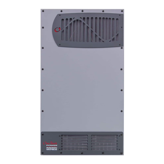
Radian
GS7048E & GS3548E Inverter/Chargers
GS7048E
GS3548E
OutBack Power's acclaimed Radian Series made the benefits of
Grid/Hybrid technology available and accessible in one agile
powerful, platform ideal for nearly all off-grid or grid-connected
system architectures.
The Radian Series GS7048E and all-new GS3548E features dual AC
inputs for grid/generator flexibility with no external switching required,
unparalleled surge capability and operational stability, easy field
upgradeability and stacking capability for large system scaling, simplified
system commissioning through a powerful, easy-to-use configuration
wizard, and multi-mode operational flexibility.
In addition, both models have new Advanced Battery Charging (ABC)
profile options to support leading-edge battery technologies such
as Lithium-Ion and others, and enhanced diagnostics for improved
performance. And both incorporate OutBack's GridZero technology, a
superior level of intelligence in energy management for self-generation
and self-consumption programs, providing precise balancing between
using stored energy, solar and utility power, blending-in the latter to
overcome surges and load spikes when needed. GridZero operation
makes it possible for a smaller inverter and battery system to perform
like a much larger one when required, putting stored and renewable
energy sources to work and minimizing grid dependence.
OutBack reserves the right to make changes to the products and information contained in this document without notice.
Copyright © 2013-2014 OutBack Power. All Rights Reserved. OutBack is a registered trademark of The Alpha Group.
Series
™
†
†
†
†
†
†
†
†
†
†
†
As truly global products, the Radian Series GS7048E and GS3548E
inverter/chargers offer selectable voltage and frequency for use in
a wide variety of locations, and innovative grid interface protection,
which allows precision programming and control to accommodate
shifting utility requirements in areas with high PV penetration or specific
interconnection requirements. Complete system interfacing using the
OutBack MATE3 and HUB communications manager enables the Radian
Series to be connected with other OutBack Power electronics providing
industry leading integration and a scalable power solution. Up to 10
units can be connected in parallel for systems up to 70kW continuous
power output.
The GS7048E and GS3548E are IEC certified to meet the most stringent
worldwide PV safety and emission standards.
This product is for Europe, Asia and other global markets.
Grid-Interactive and Stand-Alone Capability in the Same
Package
GridZero Technology Optimizes the Balance Between
Stored and Renewable Energy Sources, Minimizing Grid
Dependence
Advanced Battery Charging Profile (ABC) Supports
Leading-Edge Battery Technologies Including
Lithium-Ion
7000 and 3500 Watts of Continuous Power, Respectively
Field-Adjustable Input/Output Voltage and Frequency
Boundaries of 50/60Hz, 170-290VAC and 200-260V
Nominal, Respectively
Unsurpassed Surge Capacity
Dual AC Inputs
Field Upgradeable Firmware
Field Serviceable Modular Design
Simplified Stacking Design
GS Load Center Option Allows for Quick and
Easy Installation
Advertisement
Table of Contents
Troubleshooting

Related Manuals for OutBack Power GS7048E


Summary of Contents for OutBack Power GS7048E
- Page 1 This product is for Europe, Asia and other global markets. OutBack reserves the right to make changes to the products and information contained in this document without notice. Copyright © 2013-2014 OutBack Power. All Rights Reserved. OutBack is a registered trademark of The Alpha Group.
- Page 2 Radian Series International Specifications 06/2014 Models GS7048E GS3548E Nominal DC Input Voltage 48VDC 48VDC Continuous Output Power (@ 25°C) 7000VA 3500VA AC Output Voltage (Selectable) 230VAC (210-250VAC) 230VAC (210-250VAC) AC Output Frequency (Selectable) 50Hz (60Hz) 50Hz (60Hz) Continuous AC Output Current (@ 25°C) 30AAC 15.2AAC...
- Page 3 Radian Series Inverter/Charger GS7048E Operator’s Manual...
- Page 4 Grid/Hybrid™ As a leader in off-grid energy systems designed around energy storage, OutBack Power is an innovator in Grid/Hybrid system technology, providing the best of both worlds: grid-tied system savings during normal or daylight operation, and off-grid independence during peak energy times or in the event of a power outage or an emergency.
-
Page 5: Table Of Contents
Table of Contents Introduction....................3 Audience ....................................3 Symbols Used ..................................3 General Safety ..................................3 Welcome to OutBack Power Technologies.........................4 Functions ......................................5 MATE3 ......................................6 System Display and Controller ............................6 Commissioning ....................7 Functional Test..................................7 Pre-startup Procedures ..................................7 Startup .........................................7 Powering Down....................................8 Adding New Devices..................................8 Firmware Updates ...................................8... - Page 6 Warning Troubleshooting......................40 Table 4 Disconnect Troubleshooting ......................42 Table 5 Sell Status Messages ........................43 Table 6 Electrical Specifications for Model GS7048E.................45 Table 7 Mechanical Specifications for Model GS7048E..............46 Table 8 Environmental Specifications for All Models................46 Table 9 AS4777.3 Acceptance Settings ....................47 Table 10 GS7048E Inverter Settings ......................47...
-
Page 7: Introduction
WARNING: Limitations on Use This equipment is NOT intended for use with life support equipment or other medical equipment or devices. CAUTION: Equipment Damage Only use components or accessories recommended or sold by OutBack Power Technologies or its authorized agents. 900-0145-01-00 Rev A... -
Page 8: Welcome To Outback Power Technologies
Introduction Welcome to OutBack Power Technologies Thank you for purchasing the OutBack Radian Series Inverter/Charger. Designed for FLEXgrid™ operation, it offers a complete power conversion system between batteries and AC power. As part of an OutBack Grid/Hybrid™ system, it provides grid-interactive service, selling excess renewable energy back to the utility. -
Page 9: Functions
Operation Functions Designed for FLEXgrid operation as part of an OutBack Grid/Hybrid system Battery-to-AC inverting which delivers single-phase power (220 to 240 Vac at 50 or 60 Hz) AC-to-battery charging from any AC source Uses energy from photovoltaic arrays, wind turbines, and other renewable resources; use of OutBack FLEXmax or FLEXmax Extreme charge controllers will optimize PV power production as part of a Grid/Hybrid system. -
Page 10: Mate3
Introduction MATE3 System Display and Controller The Radian inverter/charger has no external controls. It can operate normally without an external control or interface. Basic modes and settings are pre-programmed at the factory. (See page 47 for default settings.) The Radian inverter has no display or LED indicators. It is not possible to monitor its status or operating mode without a metering device. -
Page 11: Commissioning
Commissioning Functional Test WARNING: Shock Hazard and Equipment Damage It is necessary to remove the inverter cover to perform these tests. The components are close together and carry hazardous voltages. Use appropriate care to avoid the risk of electric shock or equipment damage. Pre-startup Procedures 1. -
Page 12: Powering Down
Commissioning After programming (if any) is completed, perform the following steps: 1. If other inverters are on the system, use a DVM to verify correct voltage from the “L” OUT terminal on one inverter to the next. When stacked in parallel, the wires from one inverter to the next should read 0 Vac (although individually they should still read full voltage with respect to neutral). -
Page 13: Operation
Operation Description of Input Modes The Radian inverter has two sets of input connections for multiple AC sources. (See the Radian Series Inverter/Charger Installation Manual for more information.) With the MATE3, each input can be programmed to a particular operating mode. Six modes are available, each with certain advantages which make it ideal for a particular application. -
Page 14: Support
Operation NOTES : The Offset function of the Radian inverter is unavailable in this mode. (See page 19 for more information.) Any AC fluctuations that are accepted by the inverter will be transferred to the output. The loads will be exposed to these fluctuations. -
Page 15: Grid Tied
Operation Grid Tied IMPORTANT: Selling power to the utility company requires the authorization of the local electric jurisdiction. The method used by the local utility company to accommodate this will depend on their policies on this issue. Some may pay for power sold;... - Page 16 Operation When power is returned to the utility grid, it may be possible to make the utility meter run backwards. The net result would be to sell power to the utility company. However, this depends on whether there are other loads in the system.
-
Page 17: Ups (Uninterruptible Power Supply)
Operation UPS (Uninterruptible Power Supply) In UPS mode, the Radian’s parameters have been optimized to reduce the response and transfer times. If the utility grid becomes unstable or is interrupted, the Radian can transfer to inverting in minimal time. This allows the system to support sensitive AC loads without interruption. CHARGING : When the charger is enabled, the Radian will use the AC source to charge the battery bank. - Page 18 Operation While connected to the utility grid, any excess energy from the renewable source will be sent to the loads and used to “offset” the use of grid power. When the renewable energy is equal to or greater than the load demand, the utility grid will no longer be required. The Radian inverter will then disconnect from the utility grid and begin running from batteries again.
-
Page 19: Description Of Functions
Operation Description of Functions The items in this section are states of operation common to all Radian inverters. These functions can be used in most or all of the input modes described in the preceding section. Some can be manually selected or enabled;... -
Page 20: Search
Operation NOTE: The inverter’s operating frequency (and AC input acceptance frequency) can be changed, but this requires high-level access. (See page 11 and Table 10, which begins on page 47.) The inverter is also controlled by a high battery cut-out function. If the DC voltage rises above a certain level, the inverter will immediately stop functioning and give a High Battery V error. -
Page 21: Ac Source Acceptance
Operation Six input modes are available which affect the Radian inverter’s interactions with AC input sources. The Grid Tied mode allows the Radian to sell power using the input connection. The Support mode can use battery power to assist a smaller AC source. See page 9 for descriptions of these and other input modes. ... -
Page 22: Generator
Operation Each of the AC inputs has a settable Connect Delay. This is intended as a warmup period which allows an input source to stabilize before connection. The default setting for the Grid input is 0.2 minutes (12 seconds). ... -
Page 23: Offset
Operation The inverter does not filter or clean up the power from the AC source. The voltage and power quality received by the output loads is the same as that of the source. If the voltage or quality do not meet the inverter’s input requirements (see page 17), it will disconnect and return to the inverting mode. -
Page 24: Battery Charging
Operation Battery Charging IMPORTANT: Battery charger settings need to be correct for a given battery type. Always follow battery manufacturer recommendations. Making incorrect settings, or leaving them at factory default settings, may cause the batteries to be undercharged or overcharged. The inverter uses a “three-stage”... -
Page 25: Figure 3 Charging Stages Over Time
Operation Voltage Absorption Set Point Absorption Float Set Point Float Timer Sell Set Point Offset Offset Float Re-Float Set Point Silent Silent Bulk Charge Time Figure 3 Charging Stages Over Time Voltage Absorption Set Point Absorption Float Set Point Float Bulk No Charge Charge... - Page 26 Operation setting. (Excess current typically comes into the batteries from a PV array, wind turbine, or similar renewable energy source.) Target point: Sell Voltage setting. The default setting is 52.0 Vdc. This setting is typically lower than the Float voltage setting. Although the batteries are not discharged, they are maintained at a somewhat lower voltage so that the maximum amount of power can be exported.
-
Page 27: Figure 5 Repeated Charging Cycles
Operation Repeated Silent The unit re-enters the Silent stage as it did previously. The unit remains on the AC source, but the charger is inactive. Target point: Re-Float Voltage setting. The default set point is 50.0 Vdc. The unit will continue cycling between Float and Silent for as long as the AC source is present. However, if excess DC power is available and the battery voltage rises above the Sell Voltage set point, the unit can resume Offset activity as described on page 21. -
Page 28: Equalization
Operation If the battery voltage drops below 48.0 Vdc, the timer increments (counts upward) at double the normal rate. For example, if the batteries spent 8 minutes below this voltage, 16 minutes would be added to the Absorption timer. Similarly, if the battery voltage drops below 47.2 Vdc, the timer increments at quadruple the normal rate. -
Page 29: Battery Temperature Compensation
Operation Battery Temperature Compensation Battery performance will change when the temperature varies above or below room temperature (77°F or 25°C). Temperature compensation is a process that adjusts battery charging to correct for these changes. When a battery is cooler than room temperature, its internal resistance goes up and the voltage changes more quickly. -
Page 30: Multiple-Inverter Installations (Stacking)
It refers to how they are wired within the system and then programmed to coordinate activity. Stacking allows all units to work together as one system. The GS7048E inverter/charger can stack up to ten units in parallel for increased capacity. Three units can be stacked for three-phase output. -
Page 31: Figure 7 Example Of Parallel Stacking Arrangement (Three Inverters)
Operation Parallel Stacking (Dual-Stack and Larger) In parallel stacking, two or more inverters are stacked to create a single, common AC bus. All inverters share a common input (AC source) and run loads on a common output. The master inverter provides the primary output. -
Page 32: Power Save Levels
Operation Power Save Levels Each inverter consumes approximately 30 watts of idle power while it remains on, even if it is not actively inverting or charging. The Power Save function allows the option to put some or all slave inverters into a quiescent state known as Silent mode. This mode minimizes the inverter’s idle consumption. -
Page 33: Auxiliary Terminals
Operation Auxiliary Terminals The Radian inverter has two sets of terminals which can respond to different criteria and control many functions. The 12V AUX terminals provide a 12 Vdc output that can deliver up to 0.7 Adc to control external loads. The RELAY AUX terminals are “dry” relay contacts with no voltage. Each set of terminals has its own set of programmed criteria. - Page 34 Operation Gen Alert is used as a controller for an AC generator with a remote start feature, although it has limited functionality. (The generator recharges batteries using the inverter’s battery charger.) When the battery voltage falls to a low set point for a settable delay, the AUX output is activated. The AUX output is used to energize a relay.
- Page 35 Operation Source Status activates the AUX output whenever the inverter accepts an AC source. It can activate a light or alarm to show that the utility grid is present or that a generator has started. Alternately, it could be used to show that the source has disconnected.
-
Page 36: System Display-Based Functions
Operation System Display-Based Functions These functions require the presence of a system display such as the MATE or MATE3. If a function is set up (or already in operation) but the system display is removed, the function will not operate. Advanced Generator Start (AGS) As noted under the Gen Alert feature (see page 31), the system is capable of starting a generator. -
Page 37: Troubleshooting
Troubleshooting Basic Troubleshooting Table 1 is organized in order of common symptoms, with a series of possible causes. Each cause also shows possible troubleshooting remedies, including system display checks where appropriate. Metal pads are located at the six spots marked with “X”. In troubleshooting, AC voltages can be measured at this series of test points. - Page 38 Troubleshooting Table 1 Troubleshooting Symptom Possible Cause Possible Remedy One or more Unit is slave and is in Power MATE3 system display only: Check Power Save levels in the inverters will not Save mode. Inverter Stacking menu and test with loads. Determine if the invert while others inverter comes on at the appropriate levels.
- Page 39 Troubleshooting Table 1 Troubleshooting Symptom Possible Cause Possible Remedy Charge complete or nearly Check the DC voltage and charging stage using the MATE3, if complete. present. Confirm with DC voltmeter. MATE3’s DC meter reads Check the DC voltage on the inverter’s DC terminals. If different significantly higher than actual from the MATE3 reading, the inverter could be damaged.
- Page 40 Troubleshooting Table 1 Troubleshooting Symptom Possible Cause Possible Remedy Reduced power sold AC source voltage is driven high When the inverter senses a rise in grid voltage while selling, it to the utility grid. when the inverter sells large reduces the sell current, to avoid forcing the voltage to amounts of power.
-
Page 41: Module Select
The GS7048E can be directed to use a single, specified module (left or right), or it can be directed to turn on both modules continuously. This procedure requires high-level access and should only be performed if directed by OutBack Technical Support (see inside the front cover of this manual). - Page 42 Troubleshooting NOTES: 900-0145-01-00 Rev A...
-
Page 43: Error Messages
Troubleshooting Error Messages An error is caused by a critical fault. In most cases when this occurs, the unit will shut down. The MATE3 system display will show an event and a specific error message. This screen is viewed using the MATE3 Home screen’s soft keys. -
Page 44: Warning Messages
Troubleshooting Warning Messages A warning message is caused by a non-critical fault. When this occurs, the unit will not shut down, but the MATE3 system display will show an event and a specific warning message. This screen is viewed using the MATE3 Home screen’s soft keys. (See the MATE3 manual for more instructions.) One or more messages will display Y (yes). - Page 45 Troubleshooting Table 3 Warning Troubleshooting Message Definition Possible Remedy The inverter’s internal cooling fan is not Turn the battery disconnect off, and then on, to Fan Failure operating properly. Lack of cooling may determine if the fan self-tests. After this test, result in derated inverter output wattage.
-
Page 46: Disconnect Messages
Troubleshooting Disconnect Messages Disconnect messages explain the reason that the inverter rejected an AC source. The unit returns to inverting mode if turned on. This screen is viewed using the AC INPUT hot key on the MATE3. (See the MATE3 manual for more instructions.) One or more messages will display Y (yes). If a message says N (no), it is not the cause of the disconnect. -
Page 47: Sell Status
Troubleshooting Sell Status Sell Status messages describe conditions relating to the inverter’s grid-interactive mode. This screen is viewed using the MATE3 Home screen’s soft keys. (See the MATE3 manual for more instructions.) One or more messages will display Y (yes). If a message says N (no), it is not the cause of the disconnect. If the inverter has stopped selling or charging unexpectedly, this screen may identify the reason. - Page 48 Troubleshooting NOTES: 900-0145-01-00 Rev A...
-
Page 49: Specifications
Specifications Electrical Specifications Table 6 Electrical Specifications for Model GS7048E Specification Value Nominal DC Input Voltage 48 Vdc Continuous Output Power at 25°C 7000 VA AC Output Voltage (selectable) 230 Vac (210 – 250 Vac) AC Output Frequency (selectable) 50 or 60 Hz... -
Page 50: Mechanical Specifications
Specifications Mechanical Specifications Table 7 Mechanical Specifications for Model GS7048E Specification Value Inverter Dimensions (H x W x D) 71.1 cm x 40.6 cm x 22.2 cm (28" x 16" x 8.75") Shipping Dimensions (H x W x L) 36.8 cm x 53.3 cm x 87.6 cm (14.5" x 21" x 34.5") Inverter Weight 56.8 kg (125 lb) -
Page 51: Firmware Revision
45 Hz 55 Hz Firmware Revision This manual applies to GS7048E inverter/chargers with a firmware version of 001.003.xxx or higher. Default Settings and Ranges NOTE: Some items are retained at the present setting even when the inverter is reset to factory defaults. - Page 52 Specifications Table 10 GS7048E Inverter Settings Field Item Default Minimum Maximum 252 Vac 232 Vac 290 Vac (Voltage Limit) Upper Transfer Delay 6 AC Cycles 0 AC Cycles 240 AC Cycles Connect Delay 0.5 minutes 0.2 minutes 25 minutes AC Output...
-
Page 53: Definitions
Specifications Table 10 GS7048E Inverter Settings Field Item Default Minimum Maximum (AC Divert OFF) Delay 0.5 minutes 0.1 minutes 25 minutes Inverter Stacking Stack Mode Master Master, Slave, B Phase Master, C Phase Master Power Save Master Power Save Level... - Page 54 Specifications Table 11 Terms and Definitions Term Definition Ground, Protective Earth, PE, Grounding Electrode Conductor, and GEC ™ System technology which optimizes both grid-interactive and off-grid options Grid/Hybrid Grid-interactive, Utility grid power is available for use and the inverter is a model capable of returning (selling) grid-intertie, grid-tie electricity back to the utility grid High Battery Transfer;...
-
Page 55: Index
Index Definitions................49 Design ...................15 Disconnect................42 12V AUX................29 Diversion Control...............30 DVM..................7, 8 Absorption Stage...............20 AC Input................16 Equalization.................24 AC Source Acceptance.............17 Errors..................39 AC Test Points..............33 Adding New Devices ............8 AGS..................32 Audience ................3 Features ..................4 AUX..................29, 49 Float Stage ................22 AUX Functions Functional Test..............7 Cool Fan ................30 Functions Diversion Control............30... - Page 56 Index Settings .................47 Silent ..................28 Source Status ..............31 IEC...................50 Specifications Input Modes ..........4, 9, 16, 19, 20 Electrical................45 Input Priorities ..............16 Mechanical..............46 Inverting ................15 Environmental ..............46 Regulatory..............46 Stacking ................26 Parallel ................27 LBCO (Low Battery Cut-Out) ..........15 Three-Phase..............27 Levels, Power Save ............28 Startup..................7 LoadShed ................29 Support .................10...
- Page 57 Index...
- Page 58 Corporate Headquarters European Office 5917 – 195 St NE Hansastrasse 8 Arlington, WA 98223 USA D-91126 +1.360.435.6030 Schwabach, Germany +49.9122.79889.0 900-0145-01-00 Rev A...
-
Page 59: Installation Instructions
AC and DC voltage up to 600 volts. Requirements OutBack Power’s GS-IOB-230VAC is intended as a component for OutBack listed UL508A or UL1741 Industrial Control Panels, specifically the GSLC variants. It is intended for indoor use only. This equipment is to be installed by qualified personnel only. -
Page 60: Tools Required
GS-IOB-230VAC Installation Instructions Tools Required Philips Screwdriver Flat Screwdriver Socket Set Digital multimeter (DMM) or ohmmeter Components Figure 1 GS-IOB-230VAC Components 900-0146-01-00 REV A... - Page 61 GS-IOB-230VAC Installation Instructions Table 1 Parts List Item Quantity AC Circuit Breakers, single-pole (50 A, 250 Vac) with 6-32 x ¼" screws installed Label Set Installation Instructions Hardware Kit: Bus Bars Bus Bar Insulators, Blue Bus Bar Insulators, Brown ...
- Page 62 GS-IOB-230VAC Installation Instructions Installing the Circuit Breakers and Mechanical Bypass Assembly The simplest method to install these devices is to remove the main circuit breaker bracket from the GSLC first. To remove the main bracket: Remove the front cover (sometimes called the “front door”) of the GSLC. Open the door to 90 degrees and lift up about 1/2"...
- Page 63 GS-IOB-230VAC Installation Instructions Once the main bracket has been removed, remove the top four knockouts. Install the circuit breakers and mechanical bypass according to these steps. Place each circuit breaker behind the bracket and orient it so that the numbers read correctly. Center the device so that the raised area protrudes through the bracket.
- Page 64 GS-IOB-230VAC Installation Instructions Basic AC Wiring The GS-IOB-230VAC comes with six brown and one blue wire that are labeled according to their intended electrical connection. It also comes with an unlabeled green wire and two unlabeled short brown wires. If the preceding steps are followed, as well as the drawing in Figure 5, these wires will have sufficient length to make the intended connections.
- Page 65 GS-IOB-230VAC Installation Instructions installing bushings as necessary. Refer to the installation manuals for the Radian inverter and the GSLC for additional wiring instructions. Figure 5 Basic AC Wiring At this stage, the installation is complete. The interior cover must be re-installed using the six screws and star washers previously removed.
- Page 66 Trademarks OutBack Power, the OutBack Power logo, FLEXpower ONE, Grid/Hybrid, and FLEXgrid are trademarks owned and used by OutBack Power Technologies, Inc. The ALPHA logo and the phrase “member of the Alpha Group” are trademarks owned and used by Alpha Technologies Inc.
- Page 67 Radian Series Inverter/Charger Service Instructions Purpose and Scope These instructions detail how to replace the following parts of a Radian Series Inverter/Charger. PCBA Module (SPARE-200 and SPARE-202) The PCBA Module is a set of circuit boards that allows connection of the AC wires, MATE3, Auxiliary, and Remote Temperature Sensor (RTS) cables as well as connection to the Power Module.
- Page 68 Radian Series DC – Terminal DC – Terminal DC + Terminal DC + Terminal Figure 1 DC Terminals Verify no AC voltage is present between the following terminals and ground. These connections may be located in an electrical distribution box near the inverter. Some systems have no “L2” terminals. AC OUT HOT L1 GRID IN HOT L2 AC OUT HOT L2...
- Page 69 Part Replacement Instructions Replacement of the PCBA Module Tools Flat screwdriver with small head (4 mm wide or less) Ratchet with 8-inch extension and 10 mm socket Procedure To replace the PCBA Module: Disconnect all connections to the Auxiliary terminals, MATE3, and RTS connectors. Disconnect the AC input and output wiring by unlocking the tabs on the terminal strip (pulling them to a perpendicular position so that they stand out from the board).
- Page 70 Radian Series Remove the two lower nuts using the ratchet with a 10 mm socket. Loosen (but do not remove entirely) the two upper nuts with the ratchet with a 10 mm socket. Loosen, but do not remove these nuts Remove these nuts Figure 5 AC Terminals and PCBA Module Nuts...
- Page 71 Part Replacement Instructions Disconnect the ribbon cable from the Power Module by pressing outwards on the clips and then pulling to the right. This connection is within the Power Module. A rectangular gap is present for access to this connection. Refer to Figure 4. DC –...
- Page 72 Radian Series Replacement of the Fan Tools Short (stubby) Philips screwdriver Procedure To replace the fan: Remove the fan wire from the PCBA Module for the fan that is to be replaced by pinching its connector and pulling to the right. Refer to Figure 3. Using the short Philips screwdriver, remove the four screws attaching the fan to the Power Module.
-
Page 73: Single Inverter
(recommended), or the older revision may be re-installed. This older revision can be found on our web site or by contacting OutBack Power’s Technical Support team. Apply power to the inverter by turning on the DC circuit breakers. Keep the AC circuit breakers in the OFF position. - Page 74 OutBack Power, the OutBack Power logo, FLEXpower ONE, Grid/Hybrid, and FLEXgrid are trademarks owned and used by OutBack Power Technologies, Inc. The ALPHA logo and the phrase “member of the Alpha Group” are trademarks owned and used by Alpha Technologies Inc. These trademarks may be registered in the United States and other countries.
-
Page 75: Declaration Of Conformity
OutBack models covered by this Declaration of Conformity include the following. GS7048E IMPORTANT: This Declaration of Conformity covers only the Radian Series GS7048E. This Declaration does not cover any other models. Standard Compliance This product is certified by ETL to the following standards: ... - Page 76 +49.9122.79889.21 (Fax) +1.360.435.6019 (Fax) Email: Support@outbackpower.com Website: http://www.outbackpower.com Notice of Copyright Declaration of Conformity for Radian Series Inverter/Chargers © October 2012 by OutBack Power Systems. All Rights Reserved. Date and Revision October 2012, Revision A Part Number 907-0007-01-00 Rev A...
Need help?
Do you have a question about the GS7048E and is the answer not in the manual?
Questions and answers