OutBack Power FXR2012A Operator's Manual
Fxr series inverter/charger
Hide thumbs
Also See for FXR2012A:
- Installation manual (56 pages) ,
- Instructions manual (11 pages) ,
- Quick start manual (6 pages)

Related Manuals for OutBack Power FXR2012A


Summary of Contents for OutBack Power FXR2012A
- Page 1 FXR Series Inverter/Charger FXR2012A FXR2524A FXR3048A VFXR2812A VFXR3524A VFXR3648A Operator’s Manual...
-
Page 2: Contact Information
OutBack Power, the OutBack Power logo, Grid/Hybrid, and OPTICS RE are trademarks owned and used by OutBack Power Technologies, Inc. The ALPHA logo and the phrase “member of the Alpha Group” are trademarks owned and used by Alpha Technologies Inc. These trademarks may be registered in the United States and other countries. -
Page 3: Table Of Contents
Table of Contents Introduction ..................7 Audience ........................... 7 Symbols Used ........................... 7 General Safety .......................... 7 Welcome to OutBack Power Technologies ................8 Inverter Functions ........................9 Inverter Controls ........................10 MATE3 System Display and Controller ....................10 Operation ..................11 LED Indicators ........................ - Page 4 Table of Contents Troubleshooting ................. 47 Basic Troubleshooting ......................47 Error Messages ........................52 Warning Messages ......................... 53 Temperatures ............................. 54 GT Warnings ............................54 Disconnect Messages ......................55 Sell Status ..........................56 Specifications ..................57 Electrical Specifications ......................57 Mechanical Specifications .......................
- Page 5 Table of Contents List of Tables Table 1 Battery Indicator Values ................... 11 Table 2 Summary of Input Modes ..................21 Table 3 Charge Currents for FXR Models ................29 Table 4 Offset Interaction with AC Source ................38 Table 5 AUX Mode Functions ....................
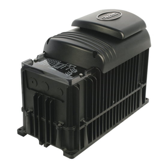
- Page 6 Table of Contents List of Figures Figure 1 FXR Series Inverter/Charger with Turbo Fan ............8 Figure 2 LED Indicators ......................11 Figure 3 Inverter Status LED Indicators ................. 12 Figure 4 Charging Stages Over Time ..................30 Figure 5 Charging Stages Over Time (24/7) ................
-
Page 7: Introduction
If this product is used in a manner not specified by GS product literature, the product’s internal safety protection may be impaired. CAUTION: Equipment Damage Only use components or accessories recommended or sold by OutBack Power Technologies or its authorized agents. 900-0167-01-01 Rev A... -
Page 8: Welcome To Outback Power Technologies
Introduction Welcome to OutBack Power Technologies Thank you for purchasing the OutBack FXR Series Inverter/Charger. It is designed to offer a complete power conversion system between batteries and AC power. As part of an OutBack Grid/Hybrid™ system, it can provide off-grid power, grid backup power, or grid-interactive service which sells excess renewable energy back to the utility. -
Page 9: Inverter Functions
This product has a settable AC output range. In this book, many references to the output refer to the entire range. However, some references are made to 120 Vac or 60 Hz output. These are intended as examples only. Outback Power Technologies Intuitive Control System for Renewable Energy 900-0167-01-01 Rev A... -
Page 10: Inverter Controls
Introduction Inverter Controls The FXR inverter has no external controls pre-installed. It can operate normally without an external control or interface. Basic modes and settings are pre-programmed at the factory. (See page 66 for default settings.) However, certain products can monitor, operate, or program the inverter. -
Page 11: Operation
Operation LED Indicators AUX Indicator (see page 41) Battery Status Indicators Indicators Figure 2 LED Indicators Battery Indicators LED indicators show the approximate battery state. (See IMPORTANT below.) The B ATTERY A green indicator (F ) means the batteries have an adequate charge at that time. It does not always mean they are full. -
Page 12: Status Indicators
Operation Status Indicators STATUS INVERTER (Green): Solid: The FXR inverter is on and providing power. • If accompanied by a solid yellow AC I indicator (2), the inverter is also connected to the utility grid with an AC input mode that uses both inverter power and grid power (Support, Grid Tied, or GridZero). -
Page 13: Inverter Functionality
Operation Inverter Functionality The FXR inverter can be used for many applications. Some of the inverter’s operations occur automatically. Others are conditional or must be enabled manually before they will operate. Most of the inverter’s individual operations and functions can be programmed using the system display. -
Page 14: Description Of Ac Input Modes
Operation Description of AC Input Modes These modes control aspects of how the inverter interacts with AC input sources. Each mode is intended to optimize the inverter for a particular application. The names of the modes are Generator, Support, Grid Tied, UPS, Backup, Mini Grid, and GridZero. The modes are summarized and compared in Table 2. -
Page 15: Support
Operation Support The Support mode is intended for systems that use the utility grid or a generator. In some cases the amount of current available from the source is limited due to size, wiring, or other reasons. If large loads are required, the FXR inverter augments (supports) the AC source. The inverter uses battery power and additional sources to ensure that the loads receive the power they demand. -
Page 16: Grid Tied
Operation Grid Tied IMPORTANT: Selling power to the utility company requires the authorization of the local electric jurisdiction. How the utility company accommodates this will depend on their policies on the issue. Some may pay for power sold; others may issue credit. Some policies may prohibit the use of this mode altogether. -
Page 17: Grid Interface Protection Menu
Operation Grid Interface Protection Menu Grid-interactive requirements vary in different locations around the world. The grid-interactive settings are adjustable in the Grid Interface Protection and Grid Support menus. These menus are only available with installer-level access. These settings are generally controlled by the local authorities or interconnection agreement and should not be altered by the end user. -
Page 18: Multi-Phase Coordination
Operation Multi-Phase Coordination Several other inverter adjustments are located in the Grid Interface Protection menu. These sensitive items can only be changed with installer-level access. The FXR inverter’s stacking function includes the option called Multi-Phase Coordination. The selectable menu item is Coordinated AC Connect/Disconnect. The default setting is No. If selected to No, the inverters will connect independently to the AC source. -
Page 19: Mini Grid
Operation Mini Grid In Mini Grid mode, the FXR inverter automatically rejects an AC source and runs solely from battery (and renewable) energy. The inverter only connects to the AC source (usually the utility grid) when the batteries run too low. The inverter runs on battery-supplied power for as long as the batteries can be sustained. -
Page 20: Gridzero
Operation GridZero In GridZero mode, the FXR inverter remains grid-connected, but prioritizes the use of battery or renewable sources to run loads. It uses only renewable energy to recharge the batteries. The inverter tries to “zero” the grid use, drawing on AC power only when needed to supplement stored DC sources. -
Page 21: Table 2 Summary Of Input Modes
Operation Table 2 Summary of Input Modes Mode Summary Benefits Cautions Intended Charger Generator Accepts power Can use AC that may be Will pass irregular or Source: Performs three- from an unusable in other modes low-quality power to the Generator stage charge and irregular or... -
Page 22: Description Of Inverter Operations
Operation Description of Inverter Operations The items in this section are operations common to all FXR inverters. These are used in most or all of the input modes described in the preceding section. Some of the items in this section are functions which can be manually selected, enabled, or customized. -
Page 23: Ac Frequency
Operation Low Battery Cut-In: The recovery point from Low Battery Cut-Out. When the DC voltage rises above this point for 10 minutes, the error will clear and the inverter will resume functioning. This item is adjustable. Connecting an AC source for the inverter to charge the batteries will also clear a low battery error. ... -
Page 24: Search
Operation Search An automated search circuit is available to minimize the power draw when no loads are present. When enabled, the inverter does not always deliver full output. The output is reduced to brief pulses with a delay between them. These pulses are sent down the output lines to see if a resistance is present. -
Page 25: Input
Operation Input When the input terminals are connected to a stable AC source, the FXR inverter will synchronize itself with that source and use it as the primary source of AC power. Its transfer relay will engage, linking the AC source directly with the inverter’s output. It can also use the source to charge batteries. -
Page 26: Ac Source Acceptance
Operation AC Source Acceptance The input source must meet the following specifications to be accepted. This is true in all modes except Grid Tied: Voltage (GRID input selection): 108 to 132 Vac Voltage (GEN input selection): 108 to 140 Vac ... -
Page 27: Generator Input
Operation Multiple Inverters In a stacked system, whenever the master inverter senses acceptable AC input, it orders the other inverters to transfer to the AC source. The AC source is expected to deliver power (in the appropriate phase) to the input of all inverters. Subphase master and slave inverters cannot transfer until the master does. -
Page 28: Transfer
Operation Transfer The inverter uses a transfer relay to alternate between the states of inverting and of accepting an AC source. Until the relay energizes, the output terminals are electrically isolated from the input. When it closes, the input and output terminals become electrically common. When the relay changes states, the physical transfer delay is approximately 16 milliseconds. -
Page 29: Battery Charging
Table 3. NOTE : This table does not match the calculations above due to other factors in charging. Table 3 Charge Currents for FXR Models Model Maximum DC Output (sent to battery) Maximum AC Input (used from source) FXR2012A 100 Adc 14 Aac VFXR2812A 125 Adc 18 Aac FXR2524A... -
Page 30: Charge Cycle
Operation Limiting Charge Current (Multiple Inverters) It is not advisable to set Charger AC Limit less than 12 Aac in a stacked system. The Power Save function requires the master inverter to activate the slave chargers in sequence only when the charge current exceeds 11 Aac. -
Page 31: Advanced Battery Charging (Abc)
Operation Advanced Battery Technologies Advanced battery technologies such as lithium-ion and sodium-sulfur may require very different settings from the inverter’s defaults or the three-stage cycle in general. The Charging Steps section describes the individual selections and behavior. All charger settings are adjustable for different priorities. - Page 32 Operation Time limit: Absorb Time setting. The charger does not necessarily run through its full duration if it retained time from a previous cycle. The timer counts down from the inception of Absorption stage until it reaches zero. The time remaining can be viewed in the system display. The Absorption timer does not reset to its maximum amount, or to zero, when AC power is disconnected or reconnected.
-
Page 33: New Charging Cycle
Operation Time limit: Float Time setting. The charger will go Silent once the timer has expired (if another stage is not still in progress.) The Float timer is reset to its maximum amount whenever the batteries decrease to the Re-Float Voltage setting. NOTE : The Float timer begins running any time the battery voltage exceeds the Float Voltage set point. -
Page 34: Figure 6 Repeated Charging (1 St And 2 Nd Cycles)
Operation Voltage Cycle 1 Cycle 2 AC Loss Silent Refloat Silent Absorption Refloat Float Float Absorption Set Point Float Set Point Re-Float Set Point Absorption Float timer Float timer runs Float timer runs timer runs Time resets (part) Inverter now charging to a new Inverter completed charging;... -
Page 35: Figure 7 Repeated Charging (3 Rd , 4 Th , And 5 Th Cycles)
Operation Cycle 3 Cycle 5 Cycle 4 AC Loss AC Loss AC Loss Bulk Abs. Bulk Absorption Silent Bulk Absorption Silent Absorption Set Point Float Set Point Re-Bulk Set Point Absorption Absorption Absorption Absorption Absorption timer resets timer runs timer runs timer timer runs (part) -
Page 36: Equalization
Operation Equalization Equalization is a controlled overcharge that is part of regular battery maintenance. Equalization brings the batteries to a much higher voltage than usual and maintains this high voltage for a period of time. This has the result of removing inert lead sulfate compounds from the battery plates. - Page 37 Operation If installed in a system networked with a HUB Communications Manager, only a single RTS is necessary. In most cases the RTS must be plugged into the master inverter. A system display must be present for the compensation values to be shared to all devices. NOTE : In the FLEXmax 100 or FLEXmax Extreme charge controller, the rate of compensation is adjustable.
-
Page 38: Offset
Operation Offset Offset is an automatic operation which occurs in certain conditions. It is not a programmable inverter function. This operation uses excess battery energy to power the loads when an AC source is present. The system can take advantage of renewable energy sources, “offsetting” dependence on the AC source. -
Page 39: Grid Support
Operation Grid Support The FXR inverter meets the definition of a “Grid Support Utility-Interactive Inverter/Converter” as described by UL 1741 SA. Grid support functionality makes use of the inverter’s capabilities to prevent destabilization of the utility grid. Grid Support functionality is only available in the Grid Tied and GridZero input modes. When either mode is selected, the settings within the Grid Support menus are active. -
Page 40: Figure 8 Grid Support Function Screen
Operation The settings for each item will vary depending on the standards being applied. Not all functions are enabled. When a particular standard is applied, the settings will be pre-loaded accordingly. The screen in Figure 8 shows which functions are enabled. Figure 8 Grid Support Function Screen When Grid Support functions require the inverter to export power to help sustain grid voltage or frequency, the inverter will do so with respect to the following limits:... -
Page 41: Auxiliary Terminals
Operation Auxiliary Terminals The FXR inverter has an auxiliary (“A “) output that responds to different criteria to control certain operations. These terminals provide a 12 Vdc output that can deliver up to 0.7 Adc. The A output has three states: continuous Off, continuous On, and Auto, which allows that output to be activated using the automatic auxiliary functions. - Page 42 Operation Settable Gen Alert parameters include: Low and high DC voltage On and off delay Gen Alert control logic is located in the inverter. It has the advantage of functioning when the system display is removed. However, it may not completely charge the batteries and does not have all the advantages of the Advanced Generator Start (AGS) function that is found in the system display.
-
Page 43: Table 5 Aux Mode Functions
Operation AC Divert activates the A output to divert (or “dump”) excess renewable energy to an AC load, usually an AC device powered by the inverter itself. This prevents overcharging of the batteries. This function can serve as rough charge regulation for an external charging source. ... - Page 44 Operation NOTES: 900-0167-01-01 Rev A...
-
Page 45: Metering
Metering MATE3-Class System Display Screens A MATE3-class system display can monitor the inverter and other networked devices. From the Home screen, the < Inverter > “soft” key accesses the inverter monitoring screens. Inverter Soft Key Figure 9 Home Screen Inverter Screen The Inverter soft key opens a screen showing the inverter operating mode, battery voltage, and status of several AC operations. -
Page 46: Battery Screen
Metering Load displays kilowatts and AC amperage consumed by devices on the inverter’s output. It can be the same as Invert. Buy displays the kilowatts and AC amperage brought into the inverter’s input for both charging and loads. This is usually a total of Charge and Load. Battery displays the uncompensated battery voltage. -
Page 47: Troubleshooting
Troubleshooting Basic Troubleshooting Table 6 is organized in order of common symptoms, with a series of possible causes. Each shows possible troubleshooting remedies, including system display checks where appropriate. These instructions are for use by qualified personnel who meet all local and governmental code requirements for licensing and training for the installation of electrical power systems with AC and DC voltage up to 600 volts. -
Page 48: Table 6 Troubleshooting
Troubleshooting Table 6 Troubleshooting Symptom Possible Cause Possible Remedy Unit is slave and is in Silent One or more units System display only: Check Power Save Levels in the mode. have no output but Inverter Stacking menu and test with loads. Determine if the others do (in multi- inverter comes on at the appropriate levels. - Page 49 Troubleshooting Table 6 Troubleshooting Symptom Possible Cause Possible Remedy Charge complete or nearly Check the DC voltage and charging stage using the system complete. display, if present. Confirm with DC voltmeter. System display DC meter Check the DC voltage on the inverter’s DC terminals. If reads significantly higher than different from the system display reading, the inverter could actual battery voltage.
- Page 50 Troubleshooting Table 6 Troubleshooting Symptom Possible Cause Possible Remedy Unusual voltage System neutral and ground Test AC H and AC N terminals with AC EUTRAL on hot or neutral may not be bonded. voltmeter. (See page 47.) These measurements should give output line.
- Page 51 Troubleshooting Table 6 Troubleshooting Symptom Possible Cause Possible Remedy Inverter’s output has been Disconnect the wires from the inverter’s AC input or AC connected to its input. output terminals, or both. If the problem immediately Voltage shifts are the result of disappears, it is an external wiring issue.
-
Page 52: Error Messages
Troubleshooting Error Messages An error is caused by a critical fault. In most cases when this occurs, the E indicator will RROR illuminate and the inverter will shut down. (See page 11 for the FXR inverter’s LED indicators.) A MATE3-class system display will show an event and a specific error message. This screen is viewed using the Home screen’s soft keys. -
Page 53: Warning Messages
Troubleshooting Warning Messages A warning message is caused by a non-critical fault. When this occurs, the E indicator will RROR flash, although the inverter will not shut down. (See page 11 for the FXR inverter’s LED indicators.) A MATE3-class system display will show an event and a specific warning message. This screen is viewed using the Home screen’s soft keys. -
Page 54: Temperatures
Troubleshooting Table 8 Warning Troubleshooting Message Definition Possible Remedy Fan Failure The inverter’s internal cooling fan is not Turn the battery disconnect off, and then on, to operating properly. Lack of cooling may determine if the fan self-tests. If it does not, result in derated inverter output wattage. -
Page 55: Disconnect Messages
Troubleshooting Disconnect Messages Disconnect messages explain why the inverter has disconnected from an AC source after previously being connected. The unit returns to inverting mode if turned on. The Last AC Disconnect screen is viewed using the AC INPUT hot key on a MATE3-class system display. One or more messages will display Y (yes). -
Page 56: Sell Status
Troubleshooting Sell Status Sell Status messages describe conditions relating to the inverter’s grid-interactive mode. This screen is viewed using the Home screen’s soft keys on a MATE3-class system display. (See the system display literature for more instructions.) One or more messages will display Y (yes). If a message says N (no), it is not the cause of the disconnection. -
Page 57: Specifications
Electrical Specifications NOTE: Items qualified with “default” can be manually changed using the system display. Table 13 Electrical Specifications for 12-Volt FXR Models Specification FXR2012A VFXR2812A Continuous Output Power at 25°C 2000 VA 2800 VA Continuous AC Output Current at 25°C 16.7 Aac... - Page 58 Specifications Table 14 Electrical Specifications for 24-Volt FXR Models Specification FXR2524A VFXR3524A Continuous Output Power at 25°C 2500 VA 3500 VA Continuous AC Output Current at 25°C 20.8 Aac 29.2 Aac AC Output Voltage (default) 120 Vac 120 Vac AC Output Frequency (default) 60 Hz 60 Hz AC Output Type...
- Page 59 Specifications Table 15 Electrical Specifications for 48-Volt FXR Models Specification FXR3048A VFXR3648A Continuous Output Power at 25°C 3000 VA 3600 VA Continuous AC Output Current at 25°C 25 Aac 30 Aac AC Output Voltage (default) 120 Vac 120 Vac AC Output Frequency (default) 60 Hz 60 Hz AC Output Type...
-
Page 60: Mechanical Specifications
Specifications Mechanical Specifications Table 16 Mechanical Specifications for FXR Models FXR2012A, FXR2524A, and VFXR2812A, VFXR3524A, Specification FXR3048A and VFXR3648A Inverter Dimensions (H x W x D) 13 x 8.25 x 16.25" (33 x 21 x 41 cm) 12 x 8.25 x 16.25" (30 x 21 x 41 cm) Shipping Dimensions (H x W x L) 21.75 x 13 x 22”... -
Page 61: Temperature Derating
77°F VFXR3648A VFXR3524A VFXR2812A FXR3048A FXR2524A FXR2012A Figure 13 Temperature Derating Regulatory Specifications Listings This product carries a listing report by ETL. It is listed to the following standards: UL 1741— Inverters, Converters, Controllers and Interconnection System Equipment for Use With ... -
Page 62: Certifications
Specifications Certifications This product has been certified by ETL to meet the following standards: 1778 — Uninterruptible Power Systems, Annex FF (normative): Backfeed Protection Test IEC 62109-1:2010 — Safety of Power Converters for use in Photovoltaic Systems Compliance ... -
Page 63: Summary Of Operating Limits
Specifications Summary of Operating Limits Severe conditions cause the inverter to limit its output or shut down for protection. The most common conditions are high voltage, low voltage, and temperature. The limits for these conditions are summarized in Table 18. See pages 52 and 54 for more information on these conditions and the warning or error messages which accompany them. - Page 64 In a stacked system (using the HUB communications manager), chargers on higher-numbered HUB ports should be turned off first. Slave chargers should be turned off before turning off any subphase masters. (See page 39 for information on stacking.) Table 19 Chargers On and Current Settings FXR2012A VFXR2812A FXR2524A VFXR3524A FXR3048A...
-
Page 65: Firmware Revision
66 to locate this command in the menu structure.) Table 20 Charge Currents for Calculations Model Maximum DC Output (sent to battery) Maximum AC Input (used from source) FXR2012A 100 Adc 14 Aac VFXR2812A 125 Adc 18 Aac... - Page 66 Grid Input AC Limit 60 Aac 5 Aac 60 Aac Current Limit Gen Input AC Limit 60 Aac 5 Aac 60 Aac FXR2012A 12 Aac 0 Aac 14 Aac Charger AC Limit VFXR2812A 16 Aac 0 Aac 18 Aac Generator, Support, UPS, Backup, Mini Grid,...
- Page 67 Specifications Table 21 FXR Menu Items for 12-Volt Models Field Item Default Minimum Maximum (Load Shed) ON: Batt > 14.0 Vdc 10.0 Vdc 18.0 Vdc (Load Shed ON) Delay 0.5 minutes 0.1 minutes 25.0 minutes (Load Shed) OFF: Batt < 11.0 Vdc 10.0 Vdc 18.0 Vdc...
- Page 68 Specifications Table 21 FXR Menu Items for 12-Volt Models Field Item Default Minimum Maximum Volts 60 Vac 0 Vac 105 Vac Low Voltage Ride Through Mode Cont. Cont., Mand., Mom., Perm., Cease (continued) Trip 0.16 seconds 0.12 seconds 21 seconds Freq.
-
Page 69: Table 22 Fxr Menu Items For 24-Volt Models
Specifications Table 22 FXR Menu Items for 24-Volt Models Field Item Default Minimum Maximum INVERTER Hot Key On, Off, or Search Inverter Mode CHARGER Hot Key Charger Control On or Off AC Input Hot Key AC Input Mode Drop or Use Sensitivity (see page 24 for increments) Search 8 AC Cycles... - Page 70 Specifications Table 22 FXR Menu Items for 24-Volt Models Field Item Default Minimum Maximum Equalize Voltage 29.2 Vdc 22.0 Vdc 34.0 Vdc Battery Equalize (Equalize) Time 1.0 hours 0.0 hours 24.0 hours Aux Control Auto Off, Auto or On Load Shed, Gen Alert, Fault, Vent Fan, Aux Mode Cool Fan Cool Fan, DC Divert, GT Limits,...
- Page 71 Specifications Table 22 FXR Menu Items for 24-Volt Models Field Item Default Minimum Maximum Volts 60 Vac 60 Vac 106 Vac Mode Cont. Cont., Mand., Mom., Perm., Cease Voltage Trip 11 seconds 1 second 50 seconds Ride- Volts 60 Vac 0 Vac 105 Vac Through...
-
Page 72: Table 23 Fxr Menu Items For 48-Volt Models
Specifications Table 23 FXR Menu Items for 48-Volt Models Field Item Default Minimum Maximum INVERTER Hot Key Inverter Mode On, Off, or Search CHARGER Hot Key Charger Control On or Off AC Input Hot Key AC Input Mode Drop or Use Sensitivity (see page 24 for increments) Search Pulse Length... - Page 73 Specifications Table 23 FXR Menu Items for 48-Volt Models Field Item Default Minimum Maximum Aux Control Auto Off, Auto or On Load Shed, Gen Alert, Fault, Vent Fan, Aux Mode Cool Fan Cool Fan, DC Divert, GT Limits, Source Status, AC Divert (Load Shed) ON: Batt >...
- Page 74 Specifications Table 23 FXR Menu Items for 48-Volt Models Field Item Default Minimum Maximum 60 Vac 60 Vac 106 Vac Volts Mode Cont. Cont., Mand., Mom., Perm., Cease Low Voltage Trip 11 seconds 1 second 50 seconds Ride-Through Volts 60 Vac 0 Vac 105 Vac (continued)
- Page 75 Specifications NOTES: 900-0167-01-01 Rev A...
-
Page 76: Definitions
Specifications Definitions The following is a list of initials, terms, and definitions used in conjunction with this product. Table 24 Terms and Definitions Term Definition Auxiliary connection that supplies 12 Vdc to control external devices Alternating Current; refers to voltage produced by the inverter, utility grid, or generator Advanced Generator Start Canadian Standards Association;... -
Page 77: Index
Index Re-Float ..........32, 34 Silent ............32 Steps............31, 33 Absorption Stage ..........31 Charging Current ........30, 63 AC Input ..........9, 13, 25 Cool Fan ............42 AC Source Acceptance ........26 CSA .............. 9, 61 AC Test Points ..........47 Advanced Generator Start (AGS) .... - Page 78 Index Grid Acceptance ..........26 Grid Interface Protection ..17, 26, 62, 70, 73 Grid Support ........... 9, 17, 39 Offset ............... 38 Grid Tie Warning ..........54 OPTICS RE ..........9, 10 Grid Tied ..........26, 54, 56 Output Grid Use Time ..........
- Page 79 Index Troubleshooting ..........47 Disconnect Messages ........55 Error Messages..........52 Vent Fan Control ..........42 Sell Status Messages ........56 Warning Messages ........53 Warning Symbol ..........7 Warnings (General).......... 53 UL 1741 ............9, 61 Warnings (Grid Tie).......... 54 Updating Firmware ...........
- Page 80 Masters of the Off-Grid.™ First Choice for the New Grid. Corporate Headquarters European Office 17825 – 59 Avenue N.E. Hansastrasse 8 Suite B D-91126 Arlington, WA 98223 USA Schwabach, Germany +1.360.435.6030 +49.9122.79889.0 900-0167-01-01 Rev A...
Need help?
Do you have a question about the FXR2012A and is the answer not in the manual?
Questions and answers