Table of Contents
Advertisement
Quick Links
Advertisement
Table of Contents
Troubleshooting

Related Manuals for OutBack Power FX Mobile Series


Summary of Contents for OutBack Power FX Mobile Series
- Page 1 FX Inverter/Charger FX and VFX Mobile Series Operator’s Manual...
- Page 2 FX and VFX Mobile Series Inverter/Charger Operator’s Manual © 2016 by OutBack Power Technologies. All Rights Reserved. Trademarks OutBack Power, the OutBack Power logo, FLEXware, and OPTICS RE are trademarks owned and used by OutBack Power Technologies, Inc. The ALPHA logo and the phrase “member of the Alpha Group” are trademarks owned and used by Alpha Technologies Inc.
-
Page 3: Table Of Contents
Table of Contents Introduction ....................... 7 Audience ......................................7 Symbols Used ....................................7 Welcome to OutBack Power Technologies ......................... 8 Inverter Functions ..................................8 General Safety ....................................9 Inverter Controls ................................... 9 System Display and Controller ................................9 ... - Page 4 Table of Contents Troubleshooting ....................... 37 Basic Troubleshooting ................................37 Error Messages ................................... 40 Warning Messages ..................................41 Disconnect Messages ................................42 Specifications ......................43 Electrical Specifications ................................43 Mechanical Specifications ..............................46 Environmental Specifications ............................... 46 Regulatory Specifications ............................... 47 ...
- Page 5 Table of Contents List of Tables Table 1 Battery Indicator Values ..........................11 Table 2 Charge Currents for FX and VFX Mobile Models ................18 Table 3 Temperature Compensation........................24 Table 4 Aux Mode Functions ............................ 34 Table 5 Troubleshooting ............................37 Table 6 ...
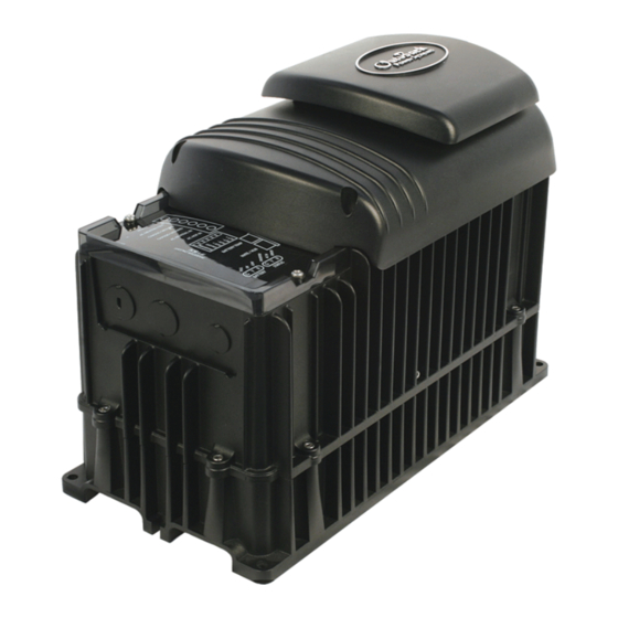
- Page 6 Table of Contents List of Figures Figure 1 FX Mobile Series Inverter/Charger with Turbo Fan ................8 Figure 2 MATE, MATE2, MATE3, and AXS Port ......................9 Figure 3 LED Indicators ..............................11 Figure 4 Inverter Status LED Indicators ........................12 ...
-
Page 7: Introduction
Introduction Audience This manual provides instructions for setup and operation of the product. It does not cover installation. The manual is intended to be used by anyone required to operate the FX or VFX Mobile Series Inverter/Charger. Operators must be familiar with all the safety regulations pertaining to operating power equipment of this type as required by local code. -
Page 8: Welcome To Outback Power Technologies
Single AC input with dual input programming; individualized priorities can be selected when switching from shore power to AC generator external switching device required system display required for individual programming Outback Power Technologies Intuitive Control System for Renewable Energy 900-0198-01-00 Rev A... -
Page 9: General Safety
If this product is used in a manner not specified by FX product literature, the product’s internal safety protection may be impaired. CAUTION: Equipment Damage Only use components or accessories recommended or sold by OutBack Power Technologies or its authorized agents. Inverter Controls The FX inverter has no external controls. -
Page 10: On/Off Switch
The switch is wired to the INVERTER ON/OFF auxiliary terminals. (See the FX Mobile Series Inverter/Charger Installation Manual for more information on wiring the switch.) This switch turns only the inverter on and off. -
Page 11: Operation
Operation LED Indicators AUX Indicator (see page 31) Battery Status Indicators Indicators Figure 3 LED Indicators Battery Indicators The Battery LED indicators show the approximate battery state. (See IMPORTANT note below.) The Battery indicators and the Inverter Status indicators are independent. They may accompany each other depending on conditions. -
Page 12: Status Indicators
Operation Status Indicators STATUS INVERTER (Green): Solid: The FX inverter is on and providing power. Flashing: The inverter has been turned on but is idle. The inverter is likely in Search mode. See page 14. Off: The inverter is off. It is not waiting to provide power. See the system display manual to turn the inverter on. -
Page 13: Ac Input Connection
The inverter can be programmed with separate input criteria for each source. See the FX Mobile Series Installation Manual for more information on connections. The inverter’s two input selections can be programmed for separate input modes (see below). The selection (Grid or Gen) can be chosen in the AC Input and Current Limit menu. -
Page 14: Dc And Ac Voltages
Operation DC and AC Voltages The FX inverter requires batteries to operate. Other sources may not maintain DC voltages that are consistent enough for the inverter to operate reliably. CAUTION: Equipment Damage Do not substitute other DC sources in place of the batteries. High or irregular voltages may damage the inverter. -
Page 15: Input
Operation NOTE: Increment sizes are difficult to define due to varying load characteristics. However, the default setting, 6 increments, is approximately sufficient to detect the load of one compact fluorescent light (CFL). A load which draws this amount or greater will “wake up”... -
Page 16: Ac Current Settings
Operation AC Current Settings The AC current settings, Grid Input AC Limit and Gen Input AC Limit, control the amount of current that the inverter draws from the source. Adjust these settings to match the input circuit breakers. The adjustment is meant to protect a generator or shore supply that cannot supply enough current for both charging and loads. -
Page 17: Generator Input
Operation Multiple Inverters In a stacked system, whenever the master inverter senses acceptable input, it orders all other inverters to transfer to the AC source. The other inverters do not use their own input readings to transfer. It is expected that the AC source delivers input (in the appropriate phase) to all inverters. ... -
Page 18: Battery Charging
Operation Battery Charging IMPORTANT: Battery charger settings need to be correct for a given battery type. Always follow battery manufacturer recommendations. Making incorrect settings, or leaving them at factory default settings, may cause the batteries to be undercharged or overcharged. Charge Current Batteries or battery banks usually have a recommended limit on the maximum current used for charging. -
Page 19: Charge Cycle
Operation Charge Current for Multiple Inverters If FX inverters are stacked, the master inverter Charger AC Limit setting is used by all other inverters. Divide the total AC current by the number of chargers used and program the master with the result. The master will operate all chargers with this setting to achieve the maximum total charge current. -
Page 20: Charging Steps
Operation Voltage No Charge Bulk Absorption Float No Charge (Source Removed) Absorption Set Point Float Set Point Time Inverter now charging to a new set point Inverter has reached the charging set point Figure 6 Charging Stages (On Setting) Charging Steps The following items describe the operation and intended use for each individual charging step as shown in the graphs. - Page 21 Operation To skip this step: Setting Absorb Voltage equal to Float Voltage causes the charger to proceed through the normal three-stage cycle, but at a single voltage. Setting Absorb Time to 0 causes the charger to skip both the Bulk and Absorption stages and proceed directly to the constant-current Refloat stage. This may not be desired if the intent is to include the Bulk stage but skip Absorption.
-
Page 22: New Charging Cycle
Operation The charger may perform two functions during Float. Both are called Float in the system display. They are defined here as Refloat and Float. Refloat Refloat is a constant-current function. The initial DC current may be as high as the charger’s maximum current, depending on conditions. -
Page 23: Equalization
Operation Equalization Equalization is a controlled overcharge that is part of regular battery maintenance. Equalization brings the batteries to a much higher voltage than usual and maintains this high voltage for a period of time. This has the result of removing inert lead sulfate compounds from the battery plates. It also reduces stratification by circulating the electrolyte. -
Page 24: Table 3 Temperature Compensation
Operation Compensation affects the Absorption, Float, and Equalization set points. The Re-Float Voltage set point is not temperature compensated. Note that the Equalization set points are not compensated in OutBack charge controllers. Table 3 Temperature Compensation Nominal Number of Compensation Maximum Voltage 2-Volt Cells... -
Page 25: Multiple-Inverter Installations (Stacking)
Slave inverters provide assistance when a master on any output cannot power the loads alone. See the FX Mobile Series Inverter/Charger Installation Manual for more information. Stacking requires CAT5 non-crossover cable used with an OutBack HUB Communications Manager (either the HUB4 or the HUB10.3). -
Page 26: Stacking Configurations
Operation Stacking Configurations Each inverter must be assigned a particular mode in the Stack Mode menu. In the figures for each configuration below, the mode names are shown next to each inverter. For example, Figure 8 shows 1-2phase Master for the first (L1) inverter in a “classic” series-stacked system. The designation for the L2 inverter is Classic Slave. -
Page 27: Parallel Stacking (Dual-Stack And Larger)
Operation LOAD PANEL OB Slave L2 2+ kVA 120 Vac 2.0 kVA 120 Vac FW-X240 4.0 kVA 240 Vac 1-2phase Master 2+ kVA 120 Vac 2.0 kVA 120 Vac Figure 9 Example of OutBack Series Stacking Arrangement Parallel Stacking (Dual-Stack and Larger) In parallel stacking, two or more inverters are stacked to create a single, common set of AC outputs. -
Page 28: Series/Parallel Stacking (Quad-Stack Or Larger)
Operation Series/Parallel Stacking (Quad-Stack or Larger) In series/parallel stacking, inverters use OutBack series stacking create separate 120 Vac output phases and 240 Vac collectively. However, in this configuration, each output has parallel inverters. One output contains the master; the other uses a slave. Each output has at least one additional slave. ... -
Page 29: Power Save
Operation Power Save Each FX inverter consumes 34 watts of idle power while it remains on, even if it is not actively inverting or charging. The Power Save function allows the option to put part of a parallel system into a quiescent state known as Silent mode. -
Page 30: Figure 14 Power Save Priority (Parallel)
Operation NOTE: The stacking designations also control which ports are used on the HUB communications manager. The master inverter must be plugged into port 1. Other ports and jumper positions vary with model and stacking configuration. IMPORTANT: Set the master rank at 0 and arrange the slave ranks in order (1, 2, 3, 4, etc.). Another order may defeat the purpose of Power Save mode. -
Page 31: Figure 15 Power Save Priority (Split-Phase)
Operation The fourth line shows that loads of 36 Aac or more (approximately 4 to 4.5 kW) are present on the system. This load causes all four inverters to be activated. The last line shows that the loads are reduced to 16 Aac. Since this load is distributed among four inverters, the master reads 4 Aac, the lower threshold for Power Save. -
Page 32: Auxiliary Terminals
Operation Auxiliary Terminals The FX inverter has a 12V AUX output which can respond to different criteria and control many operations. These terminals provide a 12 Vdc output that can deliver up to 0.7 Adc. The AUX output has three states: continuous Off, continuous On, and Auto, which allows that output to be activated using the automatic auxiliary functions. - Page 33 Operation Settable AC Divert parameters include: Low and high DC voltage On and off delay During variable conditions, the AUX output is triggered no more than once per minute (if voltage conditions are still met). This prevents rapid nuisance cycling of the AC load. ...
-
Page 34: System Display-Based Functions (Ags)
Operation Remote activates the AUX when the inverter receives an external command from the system display or a similar device. To prevent software conflicts, Remote should be selected when external functions such as AGS (see below) are used. This function does not have settable parameters. -
Page 35: Metering
Metering MATE3 Screens The MATE, MATE2, and MATE3 system displays can each monitor the FX inverter and other networked OutBack devices. Menu navigation for the MATE3 is depicted in this chapter. From the Home screen, the <Inverter> “soft” key accesses the screens for monitoring the inverter. Inverter Soft Key Figure 16 Home Screen... -
Page 36: Battery Screen
Metering Charge displays the kilowatts and AC amperage consumed for the inverter to charge the battery bank. This line also shows the present charging stage. Load displays kilowatts and AC amperage consumed by devices on the inverter’s output. It can be the same Invert ... -
Page 37: Troubleshooting
Troubleshooting Basic Troubleshooting Table 5 is organized in order of common symptoms, with a series of possible causes. Each cause also shows possible troubleshooting remedies, including system display checks where appropriate. These instructions are for use by qualified personnel who meet all local and governmental code requirements for licensing and training for the installation of electrical power systems with AC and DC voltage up to 600 volts. - Page 38 Troubleshooting Table 5 Troubleshooting Symptom Possible Cause Possible Remedy Unit is slave and is in Silent MATE3 system display only: Check Power Save levels in the mode. Inverter Stacking menu and test with loads. One or more units MATE/MATE2 system display only: Check Power Save levels in the have no output but ADV/FX/STACK menu and test with loads.
- Page 39 Troubleshooting Table 5 Troubleshooting Symptom Possible Cause Possible Remedy Unusual and Inverter has not synchronized MATE3 system display only: The AC In reading accessed by the different voltages on with input source. <Inverter> soft key may be erratic or inaccurate after initial AC hot input lines.
-
Page 40: Error Messages
Troubleshooting Error Messages An error is caused by a critical fault. In most cases when this occurs the ERROR indicator will illuminate and the inverter will shut down. (See page 11 for the FX inverter’s LED indicators.) The system display has a list of error messages. -
Page 41: Warning Messages
Troubleshooting Warning Messages A warning message is caused by a non-critical fault. When this occurs, the ERROR indicator will flash, although the inverter will not shut down. (See page 11 for the FX inverter’s LED indicators.) The system display has a list of warning messages. One or more messages will display yes in the MATE or MATE2. It will display Y in the MATE3 along with an event message. -
Page 42: Disconnect Messages
Troubleshooting Table 7 Warning Troubleshooting Message Definition Possible Remedy Displays the ambient temperature around MATE3 system display only: These values are given in Transformer (in Temps screen) the inverter’s transformer. degrees Celsius. MATE and MATE2 system display only: Values are Output FETs Displays the temperature of the FETs given in a representative “digital count”. -
Page 43: Specifications
Specifications Electrical Specifications Table 9 Electrical Specifications for 12-Volt Mobile Models Specification FX2012MT VFX2812M Continuous Output Power at 25°C 2000 VA 2800 VA Continuous AC Output Current at 25°C 16.7 Aac 23.3 Aac AC Output Voltage 120 Vac 120 Vac AC Output Frequency 60 Hz 60 Hz... -
Page 44: Table 11 Electrical Specifications For 32-Volt Mobile Models
Specifications Table 10 Electrical Specifications for 24-Volt Mobile Models Specification FX2024M FX2524MT VFX3524M Load Power Factor –1 to 1 –1 to 1 –1 to 1 AC Maximum Output Current (1 ms peak) 70 Aac 70 Aac 70 Aac AC Maximum Output Current (100 ms RMS) 50 Aac 50 Aac 50 Aac... -
Page 45: Table 12 Electrical Specifications For 36-Volt Mobile Models
Specifications Table 12 Electrical Specifications for 36-Volt Mobile Models Specification FX2536MT VFX3236M Continuous Output Power at 25°C 2500 VA 3200 VA Continuous AC Output Current at 25°C 20.8 Aac 26.6 Aac AC Output Voltage (default) 120 Vac 120 Vac AC Output Frequency (default) 60 Hz 60 Hz AC Output Type... -
Page 46: Mechanical Specifications
Specifications Table 13 Electrical Specifications for 48-Volt Mobile Models Specification FX3048MT VFX3648M AC Overload Capability (5 second) 4800 VA 5000 VA AC Overload Capability (30 minute) 3200 VA 4000 VA Power Consumption (idle) – Invert mode, no load ~23 watts ~23 watts Power Consumption (idle) –... -
Page 47: Regulatory Specifications
Specifications Regulatory Specifications Listings This product carries a listing report by ETL. It is listed to the following standards: UL 458 — Standard for Safety Power Converters/Inverters and Power Converter/Inverter Systems for Land Vehicles and Marine Crafts, ANSI/UL 458, Ed:3, dated 2006/04/19 (with revisions through and including 2013/02/20) ... -
Page 48: Default Settings And Ranges (Mate Or Mate2)
Specifications Default Settings and Ranges (MATE or MATE2) Table 17 12-Volt Inverter Settings (MATE) Field Item Default Minimum Maximum search sensitivity (see page 14 for increments) Search search pulse length 60 AC cycles 4 AC cycles 120 AC cycles search pulse spacing ac transfer control Grid Grid or Gen... -
Page 49: Table 18 24-Volt Inverter Settings (Mate)
Specifications Table 18 24-Volt Inverter Settings (MATE) Field Item Default Minimum Maximum search sensitivity (see page 14 for increments) Search search pulse length 60 AC cycles 4 AC cycles 120 AC cycles search pulse spacing ac transfer control Grid Grid or Gen Input ac1/grid limit 28 Aac... -
Page 50: Table 19 32-Volt Inverter Settings (Mate)
Specifications Table 19 32-Volt Inverter Settings (MATE) Field Item Default Minimum Maximum search sensitivity (see page 14 for increments) Search search pulse length 60 AC cycles 4 AC cycles 120 AC cycles search pulse spacing ac transfer control Grid Grid or Gen Input 28 Aac 5 Aac... -
Page 51: Table 20 36-Volt Inverter Settings (Mate)
Specifications Table 20 36-Volt Inverter Settings (MATE) Field Item Default Minimum Maximum search sensitivity (see page 14 for increments) Search search pulse length 60 AC cycles 4 AC cycles 120 AC cycles search pulse spacing ac transfer control Grid Grid or Gen Input 28 Aac 5 Aac... -
Page 52: Table 21 48-Volt Inverter Settings (Mate)
Specifications Table 21 48-Volt Inverter Settings (MATE) Field Item Default Minimum Maximum search sensitivity (see page 14 for increments) Search search pulse length 60 AC cycles 4 AC cycles 120 AC cycles search pulse spacing ac transfer control Grid Grid or Gen Input 28 Aac 5 Aac... -
Page 53: Default Settings And Ranges (Mate3)
Specifications Default Settings and Ranges (MATE3) Table 22 12-Volt Inverter Settings (MATE3) Field Item Default Minimum Maximum INVERTER Hot Key Inverter Mode On, Off, or Search CHARGER Hot Key Charger Control On or Off AC Input Hot Key AC Input Mode Drop or Use Sensitivity (see page 14 for increments) Search... -
Page 54: Table 23 24-Volt Inverter Settings (Mate3)
Specifications Table 23 24-Volt Inverter Settings (MATE3) Field Item Default Minimum Maximum INVERTER Hot Key On, Off, or Search Inverter Mode CHARGER Hot Key Charger Control On or Off AC Input Hot Key AC Input Mode Drop or Use Sensitivity (see page 14 for increments) Search Pulse Length 8 AC Cycles... -
Page 55: Table 24 32-Volt Inverter Settings (Mate3)
Specifications Table 24 32-Volt Inverter Settings (MATE3) Field Item Default Minimum Maximum INVERTER Hot Key Inverter Mode On, Off, or Search CHARGER Hot Key Charger Control On or Off AC Input Hot Key AC Input Mode Drop or Use Sensitivity (see page 14 for increments) Search Pulse Length 8 AC Cycles... -
Page 56: Table 25 36-Volt Inverter Settings (Mate3)
Specifications Table 25 36-Volt Inverter Settings (MATE3) Field Item Default Minimum Maximum INVERTER Hot Key Inverter Mode On, Off, or Search CHARGER Hot Key Charger Control On or Off AC Input Hot Key AC Input Mode Drop or Use Sensitivity (see page 14 for increments) Search Pulse Length 8 AC Cycles... -
Page 57: Table 26 48-Volt Inverter Settings (Mate3)
Specifications Table 26 48-Volt Inverter Settings (MATE3) Field Item Default Minimum Maximum INVERTER Hot Key Inverter Mode On, Off, or Search CHARGER Hot Key Charger Control On or Off AC Input Hot Key AC Input Mode Drop or Use Sensitivity (see page 14 for increments) Search Pulse Length 8 AC Cycles... -
Page 58: Definitions
Specifications Definitions The following is a list of initials, terms, and definitions used in conjunction with this product. Table 27 Terms and Definitions Term Definition Alternating Current; refers to voltage produced by the inverter, utility grid, or generator Advanced Generator Start Inverter’s 12-volt auxiliary output Communications Multi-port device such as the OutBack HUB 4 or HUB10.3;... -
Page 59: Index
Index Silent ................21 Steps ................. 20, 22 Charging Current ............19, 30 12V AUX ..................32 Communications Manager ..........25 Stacking ............26, 27, 28 Cool Fan ..................32 CSA C22.2 ................8, 47 Absorption Stage ..............21 AC Input ................ - Page 60 Index GenAlert ................... 33 Safety ................... 7 Generator Search ..................14 Sizing ................17 Series Stacking ................ 26 Series/Parallel Stacking ............28 Settings MATE or MATE2 ........ 48, 49, 50, 51, 53 MATE3 ..........54, 55, 56, 57, 58 High Battery Cut-Out ............
- Page 61 Index UL458 ..................8, 47 Warning Symbol ............... 7 Warnings .................. 41 Vent Fan Control ..............33 900-0198-01-00 Rev A...
- Page 62 Index This page intentionally left blank. 900-0198-01-00 Rev A...
- Page 63 Index This page intentionally left blank. 900-0198-01-00 Rev A...
- Page 64 Masters of the Off-Grid.™ First Choice for the New Grid. Corporate Headquarters European Office 17825 – 59 Avenue N.E. Hansastrasse 8 Suite B D-91126 Arlington, WA 98223 USA Schwabach, Germany +1.360.435.6030 +49.9122.79889.0 900-0198-01-00 Rev A...
Need help?
Do you have a question about the FX Mobile Series and is the answer not in the manual?
Questions and answers