
Related Manuals for OutBack Power GS Load Center Series


Summary of Contents for OutBack Power GS Load Center Series
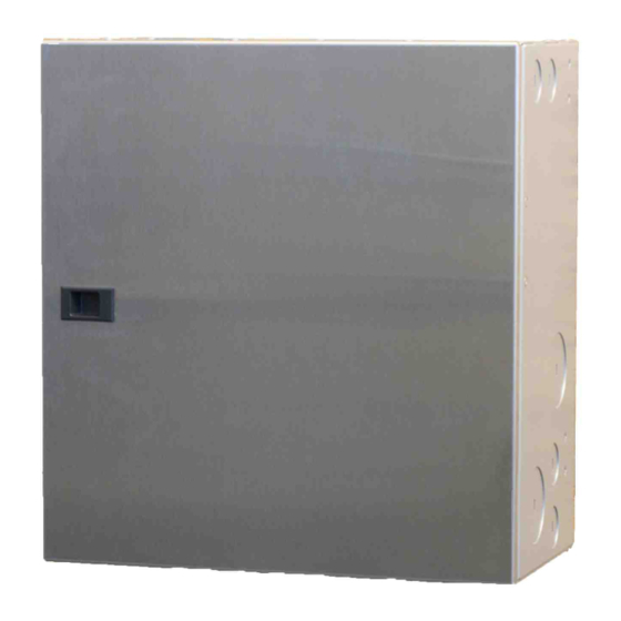
- Page 1 GS Load Center Installation Manual PDF compression, OCR, web optimization using a watermarked evaluation copy of CVISION PDFCompressor...
-
Page 2: Contact Information
USE OF ANY SUCH INFORMATION WILL BE ENTIRELY AT THE USER’S RISK. Warranty Summary OutBack Power Technologies Inc. warrants that the products it manufactures will be free from defects in materials and workmanship for a period of five (5) years subject to the conditions set forth in the warranty detail, found inside the back cover of this manual. -
Page 3: Important Safety Instructions
Important Safety Instructions READ AND SAVE THESE INSTRUCTIONS! This manual contains important safety instructions for the GS Load Center. Read all instructions and cautionary markings on the GS Load Center and on any accessories or additional equipment included in the installation. Failure to adhere to these instructions could result in severe shock or possible electrocution. -
Page 4: Definitions
This equipment is NOT intended for use with life support equipment or other medical equipment or devices. CAUTION: Equipment Damage Only use components or accessories recommended or sold by OutBack Power Technologies or its authorized agents. IMPORTANT: Do not attempt to install this equipment if it appears to be damaged in any way. -
Page 5: Inverter Safety
Do not perform any servicing other than that specified in the installation instructions unless qualified to do so and have been instructed to do so by OutBack Power Technologies Technical Support personnel. WARNING: Burn Hazard Internal parts can become hot during operation. Do not remove the cover during operation or touch any internal parts. -
Page 6: Battery Safety
Important Safety Instructions Battery Safety WARNING: Explosion, Electrocution, or Fire Hazard Use the battery types recommended by OutBack Power Technologies. Follow the battery manufacturer’s recommendations for installation and maintenance. Ensure the cables are properly sized. Failure to size the cables properly can results in a fire hazard. -
Page 7: Required Resources
Important Safety Instructions Required Resources This product is required to be installed according to pertinent safety codes and standards. If installed in the United States, wiring practices must meet the requirements of the National Electrical Code (NEC). If installed in Canada, wiring practices must meet the requirements of the Canadian Electrical Code. - Page 8 Important Safety Instructions Keep America Beautiful, USA Web site: www.kab.org/ Email: info@kab.org Address: 1010 Washington Boulevard Stamford, CT 06901 Phone: +1.203.659.3000 (Main number) Fax: +1.203.659.3001 Natural Resources Canada Web site: http://www.nrcan-rncan.gc.ca/mms-smm/busi-indu/rec-rec-eng.htm Address: 580 Booth, Ottawa, ON K1A 0E8 Phone: +1.613.995.0947 TTY: +1.613.996.4397 (Phone and TTY: Monday to Friday, 8:30 a.m.
-
Page 9: Table Of Contents
Definitions....................................2 General Safety ..................................2 Required Resources ................................5 Additional Resources ................................5 Recycling Information ................................5 Introduction....................9 Welcome to OutBack Power Technologies.........................9 GSLC – Components ................................ 10 GSLC175-120/240 – Components..........................11 GSLC175-PV-120/240 – Components ........................12 Planning ....................13 Tools Required..................................13 Materials Required ................................13 Location/Environmental Requirements........................ - Page 10 Table of Contents Warranty....................45 How to Arrange for Warranty Service ........................46 Contacting OutBack ..................................46 Troubleshooting.....................................46 Return Material Authorization (RMA)............................46 Returning Product to OutBack ..............................47 Index ......................51 List of Tables Table 1 Terms and Definitions ........................2 Table 2 Bus Bar and Circuit Breaker Size and Torque Requirements ..........17 Table 3 Terminal Bus Bar (TBB) Wire Size and Torque Requirements .........27 Table 4...
-
Page 11: Introduction
Introduction Welcome to OutBack Power Technologies Thank you for purchasing a GS Load Center (GSLC) from OutBack Power Technologies. The GSLC is a balance-of-systems enclosure intended to work with the Radian Series (GS) inverter/chargers, FLEXmax Charge Controllers, and OutBack HUB Communications Manager. -
Page 12: Gslc - Components
Introduction GSLC – Components Legend Inverter (negative) DC Bus Bars Inverter positive DC bus bars and DC Negative Terminal Bus Bar (TBB) positive bus plate are also included in kit. Ground TBB Neutral TBB PV (Positive) TBBs Shunt Figure 2 GSLC 900-0123-01-00 Rev PDF compression, OCR, web optimization using a watermarked evaluation copy of CVISION PDFCompressor... -
Page 13: Gslc175-120/240 - Components
Introduction GSLC175-120/240 – Components Legend Inverter (negative) DC Bus Bars Inverter (positive) DC Bus Bars Negative Terminal Bus Bar (TBB) Shunt Ground TBB AC Circuit Breakers Neutral TBB Maintenance Bypass Interlock PV TBBs AC TBBs (Inverter Output) L1, L2 DC Positive Cable Plate AC TBBs (Grid) L1, L2 Main Inverter Disconnect(s) AC TBBs (Generator) L1, L2... -
Page 14: Gslc175-Pv-120/240 - Components
Introduction GSLC175-PV-120/240 – Components Legend Inverter (negative) DC Bus Bars AC Circuit Breakers Negative Terminal Bus Bar (TBB) Maintenance Bypass Interlock Ground TBB AC TBBs (Inverter Output) L1, L2 Neutral TBB AC TBBs (Grid) L1, L2 PV TBBs AC TBBs (Generator) L1, L2 DC Positive Cable Plate PV Input Disconnects Main Inverter Disconnect(s) -
Page 15: Planning
Planning Tools Required Open-ended wrenches (13 mm and 9/16") Wire cutters/strippers Torque wrenches Assorted insulated screwdrivers Digital Voltmeter (DVM) or Regular Voltmeter Materials Required Conductors for wiring Conduits Location/Environmental Requirements Indoor mount only Front View Side View 8½”... - Page 16 Planning Legend Mounting holes for HUB 2” Knockouts 1½” Knockouts Mounting holes for FLEXmax 1¼” Knockouts 1” Knockouts ¾” Knockouts ½” Knockouts Top View Side View Side View Bottom View Figure Knockouts and Mounting Holes for FLEXmax and HUB 900-0123-01-00 Rev PDF compression, OCR, web optimization using a watermarked evaluation copy of CVISION PDFCompressor...
-
Page 17: Installation
Installation Hardware Options The three versions of the GSLC come with different components already installed. GSLC, the “basic” or “empty” version, requires almost all components to be installed if they are needed. Instructions for this product begin on page 17. ... -
Page 18: Remove Top Cover
Installation Remove Top Cover To Remove the Top Cover: Remove the four screws; one in each corner. Lift the top off the enclosure. Enclosure with Top Removed Figure 9 Removing the Top Cover from the GSLC Remove Front Door To Remove the Front Door: Open the door to about 90 degrees. -
Page 19: Remove Interior Cover
Assembly Remove Interior Cover In order to make any wiring connections or install components, the interior cover must be removed to expose the interior of the enclosure. Remove (x3) To Remove the Interior Cover: Remove the three screws along the top of the enclosure. -
Page 20: Assembling Dc Positive Cable Plate
Installation Assembling DC Positive Cable Plate The bottom of each DC disconnect is bolted to a bus plate which receives the inverter’s positive battery cables. To assemble the DC Positive Plate: Remove the nuts and other hardware (washer, lock washer, hex nut) from the bottom terminal in the back of each DC disconnect. -
Page 21: Installing Inverter Positive Bus Bars
Assembly Installing Inverter Positive Bus Bars The GSLC parts kit contains two bus bars which attach to the tops of the DC disconnects. These bus bars make the connections with the Radian inverter’s positive DC terminals. Although they have similar shapes, the bus bars are not interchangeable. -
Page 22: Installing Inverter Main Disconnects
Installation Installing Inverter Main Disconnects To mount the inverter disconnects: If the negative top bar is installed, loosen or remove it. Slide the disconnect assembly through the opening in the top of the GSLC and place it behind the premounted bracket. Center the disconnect assembly so that the raised area around the switch protrudes through the bracket. -
Page 23: Installing Dc Shunts
Assembly Installing DC Shunts A single 500 Adc/50 mV shunt is included with the GSLC. Up to two more shunts can be installed as needed. These shunts are used in conjunction with the FLEXnet DC battery monitor. See page 29 for more instructions on wiring. -
Page 24: Installing Pv And Ac Circuit Breakers And Gfdi
Installation Installing PV and AC Circuit Breakers and GFDI To mount circuit breakers: It may be necessary to remove the knockout from the location where the circuit breaker is to be placed to make room for the circuit breaker to be installed. Be sure to remove any debris that may occur from removing the knockout. - Page 25 Assembly Mounting on the Inverter IMPORTANT: The Radian inverter and GSLC are intended for indoor use only. Ensure that the mounting surface is strong enough to support the full weight of the Radian inverter/charger and the GSLC. If in doubt, use a ¾“ sheet of plywood to strengthen the wall surface.
- Page 26 Installation ...continued from the previous page. Bottom Screws Keyhole Slots Keyhole Slots Re-hang the GSLC using the keyhole mounts. Secure to the mounting surface using all four mounting feet holes. Using the bolts provided on the Radian inverter’s battery terminals, connect the terminals to the GSLC’s inverter bus bars.
-
Page 27: Mounting Charge Controller
Assembly Mounting Charge Controller The GSLC enclosure accommodates up to two FLEXmax charge controllers and a HUB Communications Manager. To mount the FLEXmax Charge controller to the side of the GSLC enclosure: Align the brackets to the mounting holes and secure the brackets to the sides of the enclosure with the hardware provided with the brackets. -
Page 28: Mounting The Hub Communications Manager
Installation Mounting the HUB Communications Manager The GSLC provides mounting holes to support a HUB Communications Manager. To mount the HUB Communications Manager to the side of the GSLC enclosure: Locate the mounting holes on the side of the GSLC enclosure as shown in Figure 6 on page 14. -
Page 29: Wiring
Wiring Wiring Table 3 Terminal Bus Bar (TBB) Wire Size and Torque Requirements Conductor Size Torque Requirements In-lb #14 – #10 2.5 – 4 6 – 10 #6 – #3 16 – 25 #1 – 1/0 Grounding WARNING: Shock Hazard The unit must be connected to a grounded, permanent wiring system. - Page 30 Installation Bonding The GSLC is equipped with a mechanical bond between AC neutral and ground. It is also equipped with a mechanical bond between DC negative and ground. These can be useful in stand-alone systems where no other bond is provided. If other bonds are present, however, the GSLC bonds need to be removed.
-
Page 31: Dc Wiring
Wiring DC Wiring WARNING: Shock Hazard Ensure all circuit breakers or disconnect devices are turned off or disconnected before wiring. Inverter Wiring The DC disconnects are connected directly to the inverter using bus bars during the process of mounting. See page 24 for more information. Battery Wiring The Radian inverter requires two positive and two negative cables for proper installation. - Page 32 Installation Installing the FLEXnet DC The OutBack FLEXnet DC (FNDC), or a similar battery monitor, may be added to the GSLC for observing DC current flow and providing battery state-of-charge information. HUB port Wiring block Figure FNDC and Wiring Block To install the FN-DC : Assemble the FNDC wiring as shown in the manual for the FNDC.
- Page 33 Wiring DC Devices In addition to inverter- or PV-related connections, other devices may be connected to the GSLC, such as DC loads or sources. The wiring on these devices will vary with the application. In most cases the device will have a separate circuit breaker which is mounted on the rail as shown on page 22. It will be wired into the battery system using the existing bus bars or shunts.
- Page 34 Installation Negative TBB Shunt PV positive plate GFDI PV disconnect PV positive TBB Figure PV Connections in the GSLC Battery Positive PV Positive PV– BAT– BAT+ Battery Negative PV Negative Figure PV Connections in the FLEXmax Charge Controller 900-0123-01-00 Rev PDF compression, OCR, web optimization using a watermarked evaluation copy of CVISION PDFCompressor...
-
Page 35: Ac Wiring
Wiring AC Wiring WARNING: Shock Hazard Ensure all circuit breakers or disconnect devices are turned off or disconnected before wiring. Make certain the inverter and other active devices are turned off or disabled before wiring. The GSLC can have multiple terminal bus bars for multiple AC connections. Because the Radian inverter possesses two sets of AC input connections and one set of output connections, up to three TBB sets are available. - Page 36 Installation To make the connections to the Radian inverter: (See Figure 33 on page 38.) Choose the AC circuit breaker set at the top and designate it as the inverter AC output disconnect. Install a wire from the black TBB of Upper pole the AC output circuit (as shown in Figure 28) to the right side of the...
-
Page 37: Installing The Ac Bypass Assembly
Wiring Installing the AC Bypass Assembly The GSLC175-120/240 and GSLC175-PV-120/240 comes equipped with a maintenance bypass assembly. The GSLC can be equipped with a bypass assembly using the GS-IOB accessory kit. The GS-IOB should be installed according to its own instructions. Once installed, it can be wired by following the steps shown here. -
Page 38: Multiple-Inverter Installations (Stacking Inverters)
Installation Multiple-Inverter Installations (Stacking Inverters) When multiple Radian inverters are stacked for additional power, the basic wiring is repeated for each inverter. However, several factors need to be considered. One GSLC is required per Radian inverter. A single GSLC cannot be sized to handle the requisite current for multiple Radian inverters. - Page 39 Wiring WARNING: Shock Hazard or Equipment Damage Using independent bypass devices on multiple inverters can result in power being routed to inappropriate places. This could lead to an electric shock, or to equipment damage. External Bypass Device Output Wiring Input Wiring Inactive Radian Inverters AC Loads AC Source...
- Page 40 Installation Figure Wiring Diagram – GSLC175-120/240 System 900-0123-01-00 Rev PDF compression, OCR, web optimization using a watermarked evaluation copy of CVISION PDFCompressor...
- Page 41 Wiring Figure Wiring Diagram – GSLC175-PV-120/240 System 900-0123-01-00 Rev PDF compression, OCR, web optimization using a watermarked evaluation copy of CVISION PDFCompressor...
- Page 42 Installation THIS PAGE INTENTIONALLY LEFT BLANK. 900-0123-01-00 Rev PDF compression, OCR, web optimization using a watermarked evaluation copy of CVISION PDFCompressor...
-
Page 43: Specifications
Specifications Electrical Specifications Table 4 Electrical Specifications Specification Measurement Maximum Input Voltage 600 Volts Maximum Input Current 500 Amps Operating Frequency Range 50/60 Hz to DC Mechanical Specifications Table 5 Mechanical Specifications Specification Measurement Dimensions (H x W x D) 17“... - Page 44 Specifications THIS PAGE INTENTIONALLY LEFT BLANK. 900-0123-01-00 Rev PDF compression, OCR, web optimization using a watermarked evaluation copy of CVISION PDFCompressor...
-
Page 45: Product Registration
Product Registration The purchase of an OutBack Power Technologies product is an important investment. Registering the products will help us maintain the standard of excellence you expect from us in terms of performance, quality and reliability. Please take a moment to register and provide us with some important information. - Page 46 Installer Telephone/E-mail Please check ALL factors affecting purchase decision: Grid-Interactive Capability Product Reputation Back-up Capability Reputation of OutBack Power Technologies Value Looks Other 900-0123-01-00 Rev PDF compression, OCR, web optimization using a watermarked evaluation copy of CVISION PDFCompressor...
-
Page 47: Warranty
5-Year Limited Warranty for the GS Load Center 4 0 B 4 0 B OutBack Power Technologies, Inc. (“OutBack”) provides a five-year (5) limited warranty (“Warranty”) against defects in materials and workmanship for its GS Load Center (“Product”). The term of this Warranty begins on the Product(s) initial purchase date, or the date of receipt of the Product(s) by the end user, whichever is later. -
Page 48: How To Arrange For Warranty Service
Warranty Information How to Arrange for Warranty Service During the warranty period beginning on the invoice date, OutBack Power Technologies will repair or replace products covered under this limited warranty that are returned to OutBack Power Technologies’ facility or to an OutBack Power Technologies authorized repair facility, or that are repaired on site by an OutBack Power Technologies authorized repair person. -
Page 49: Returning Product To Outback
If Product is within the warranty period, OutBack will cover pre-paid shipping with prior arrangement. The Product(s) must be shipped back to OutBack Power Technologies in their original or equivalent packaging, to the following address:... - Page 50 NOTES NOTES: 900-0123-01-00 Rev PDF compression, OCR, web optimization using a watermarked evaluation copy of CVISION PDFCompressor...
- Page 51 NOTES NOTES: 900-0123-01-00 Rev PDF compression, OCR, web optimization using a watermarked evaluation copy of CVISION PDFCompressor...
- Page 52 NOTES NOTES: 900-0123-01-00 Rev PDF compression, OCR, web optimization using a watermarked evaluation copy of CVISION PDFCompressor...
-
Page 53: Index
Index AC Bypass Assembly............35 Hardware Option...............15 AC Circuit Breakers............22 HUB Communications Manager........26 AC Terminal Bus Bars............33 Audience ................1 IEEE ..................41 Interior Cover ..............17 Bypass Switches ..............36 Internal Hardware .............17 Bypass Switching for Multiple Inverters ....37 Inverter Main Disconnects..........20 Inverter Positive Bus Bars..........19 Charge Controller..............25 Circuit Breaker Size ............17 Knockouts ................14... - Page 54 Index Troubleshooting ..............46 Safety..................1 Battery ................4 General ................2 UL ....................41 Inverter................3 Personal ................2 PV ..................3 Specifications Warranty ................2, 45 Electricai................41 How to Arrange for Service ........46 Mechanical..............41 RMA ..................46 Regulatory..............41 Terms and Conditions ..........45 Stacking Inverters..............36 Wire Size and Torque Requirements......27 Symbols Used ...............1 Wiring AC ..................33...
- Page 55 THIS PAGE INTENTIONALLY LEFT BLANK. PDF compression, OCR, web optimization using a watermarked evaluation copy of CVISION PDFCompressor...
- Page 56 North America European Office: 5917 – 195 St N.E., #7 Barcelona, Spain Arlington, WA USA +34.93.654.9568 +1.360.435.6030 900-0123-01-00 Rev A PDF compression, OCR, web optimization using a watermarked evaluation copy of CVISION PDFCompressor...
Need help?
Do you have a question about the GS Load Center Series and is the answer not in the manual?
Questions and answers