OutBack Power GS8048A Quick Start Manual
Radian series inverter/charger
Hide thumbs
Also See for GS8048A:
- Installation manual (48 pages) ,
- Operator's manual (72 pages) ,
- Quick start manual (4 pages)
Table of Contents
Advertisement
Quick Links
Specifications
Environmental Specifications
Specification
Rated Temperature Range (meets component specifications; however, please note
that the inverter output wattage is derated above 25°C)
Operational Temperature Range (functions, but not rated for operation; does not
necessarily meet all component specifications)
Storage Temperature Range
IP (Ingress Protection) Rating of Enclosure
Environmental Category
Wet Locations Classification
Relative Humidity Rating
Pollution Degree Classification
Maximum Altitude Rating
Overvoltage Category (AC Input)
Overvoltage Category (DC Input)
All Radian inverters can deliver their full rated wattage at temperatures up to 25°C (77°F). The Radian
maximum wattage is rated less in higher temperatures. Above 25°C, the GS8048A is derated by a factor of 80
VA for every increase of 1°C. The GS4048A is derated by 40 VA per 1°C. This derating applies to all power
conversion functions (inverting, charging, selling, offsetting, etc.)
IMPORTANT:
This inverter is intended for indoor use only. Failure to
adequately protect the inverter will void the warranty.
Contact Information
Mailing Address:
Corporate Headquarters
th
17825 – 59
Avenue NE
Suite B
Arlington, WA 98223 USA
Web Site:
www.outbackpower.com
Warranty Summary
OutBack Power Technologies warrants that the products it manufactures will be free from defects in materials and workmanship for a period of
five (5) years subject to the conditions set forth in the warranty documentation.
OutBack Power Technologies cannot be responsible for system failure, damages, or injury resulting from improper installation of their products.
Notice of Copyright
Radian Series Inverter/Charger Quick Start Guide © 2017 by OutBack Power Technologies. All Rights Reserved.
Date and Revision
July 2017, Revision A
900-0162-01-01 REV A Sheet 1 of 3
©2017 OutBack Power Technologies. All Rights Reserved.
Value
–4°F to 122°F (–20°C to 50°C)
–40°F to 140°F (–40°C to 60°C)
–40°F to 140°F (–40°C to 60°C)
IP20
Indoor, Unconditioned
Wet locations: No
93%
PD 2
6561' (2000 m)
3
1
European Office
Hansastrasse 8
D-91126
Schwabach, Germany
Quick Start Guide
RADIAN Series Inverter/Charger
This Quick Start Guide is printed in unbound format. The pages can be read in any order, or shown alongside one another.
WARNING: Fire/Explosion Hazard
Do not place combustible or flammable materials within 12 feet (3.7 m) of the equipment.
This unit employs mechanical relays and is not ignition-protected. Fumes or spills from
flammable materials could be ignited by sparks.
WARNING: Personal Injury
Use safe lifting techniques and standard safety equipment when working with this equipment.
IMPORTANT:
Clearance and access requirements may vary by location. Maintaining a 36" (91.4 cm) clear space
in front of the system for access is recommended. Consult local electric code to confirm clearance
and access requirements for the specific location.
IMPORTANT:
These instructions are for use by qualified personnel who meet all local and governmental code requirements for licensing
and training for the installation of electrical power systems with AC and DC voltage up to 600 volts. This product is only
serviceable by qualified personnel.
NOTE:
For specifications, functions, applications, stacking, and programming instructions (or if installing with hardware not sold by
OutBack), see the Radian product literature. For menu navigation, see the system display product literature. These
documents are available at www.outbackpower.com.
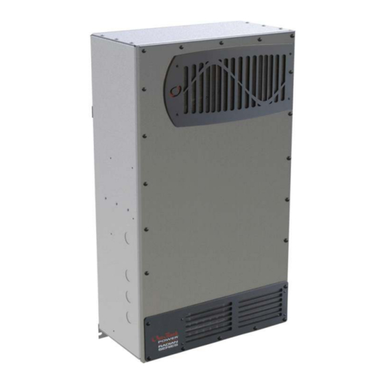
Radian Inverter/Charger
MATE3s
System
Display and
Controller
HUB 10.3
Communications
Manager
GS Load Center
(GSLC)
Major Components
Radian
Inverter/Charger
Radian System Products
(optional; depicted as being installed)
GS Load Center
System Display
and Controller
Communications
Manager
Charge Controller
FLEXmax 80 depicted
FM80 Charge
Controllers
FLEXnet DC Monitor (FN-DC)
(x2)
Remote Temperature Sensor
Other Components
Battery Bank
Utility Grid or
AC Source
AC Generator
Main Electrical Panel and
Distribution Subpanel (Load Panel)
Photovoltaic (PV) Array and Combiner
IMPORTANT:
Not intended for use with
life support equipment.
GS8048A
GS4048A
GSLC175-PV-120/240
GSLC175PV1-120/240
(both depicted)
MATE3s depicted
HUB10.3 depicted
Advertisement
Table of Contents

Subscribe to Our Youtube Channel
Related Manuals for OutBack Power GS8048A


Summary of Contents for OutBack Power GS8048A
-
Page 1: Quick Start Guide
Controllers FLEXnet DC Monitor (FN-DC) OutBack Power Technologies warrants that the products it manufactures will be free from defects in materials and workmanship for a period of (x2) five (5) years subject to the conditions set forth in the warranty documentation. -
Page 2: Tools Required
Radian system. The Radian has one mounting location for the HUB product. The GSLC also has one location. 12.0" (31.8 cm) 900-0162-01-01 REV A Sheet 1 of 3 ©2017 OutBack Power Technologies. All Rights Reserved. - Page 3 GSLC meets this requirement. Note that the GSLC top can be removed for access. GSLC175PV-120/240 GSLC175PV1-120/240 GEN IN Bus Bar L2 The modular construction of the GS8048A requires two DC circuit breakers or fuses. Both sets of positive terminals must be connected to battery power. AC Neutral...
- Page 4 18. Turn on the AC disconnects at the backup (or critical) load panel and test the loads. Verify 0 Vac on the AC output circuit breakers by placing the connections at the source. voltmeter leads on . Repeat this step for 900-0162-01-01 REV A Sheet 2 of 3 ©2017 OutBack Power Technologies. All Rights Reserved.
- Page 5 To AC, DC, and PV as shown to the left Neutral (RJ45) (RJ11) (RJ45) (RJ11) Generator Hot L1 Hot L2 PV Array #1 and #2 Ground Battery Bank Negative Subpanel Battery Positive with Loads Positive 900-0162-01-01 REV A Sheet 3 of 3 ©2014 OutBack Power Technologies. All Rights Reserved.
- Page 6 Continue Back Continue display advances to the Shunt screens. If the FLEXnet DC is not installed, see This advances the display to the Setup Complete screen. 900-0162-01-01 REV A Sheet 3 of 3 ©2014 OutBack Power Technologies. All Rights Reserved.
Need help?
Do you have a question about the GS8048A and is the answer not in the manual?
Questions and answers