Advertisement
Specifications
Listings:
th
o
UL1778 5
Edition, 6/13/2016
nd
UL1741 2
Edition, 1/28/2010 with supplement SA
o
CSA22.2, No. 107.1-01 Ed:3 (R2006)
o
Certifications:
HECO Rule 14 SRD
o
o
California Rule 21 SRD
o
IEEE 1547-2003
IEEE 1547.1-2005
o
System Grounding and Bonding:
In this product, the PV, AC, and battery circuits are
isolated from the enclosure. This product has been
evaluated, listed and identified by UL to meet the
requirements of 690.41 and 250.4(A) of the NEC.
o
The PV system ground reference and protection
is provided internal to the SkyBox, in accordance
with NFPA 70 690.41(A)(6).
o
The AC connections are not bonded to ground.
The usual location for a neutral-ground bond is
at the main AC service panel. Make sure to
establish a neutral-ground bond when installing
in an off-grid application.
The battery connection is not bonded to ground.
o
Make sure to establish a negative-ground bond for
each battery system.
Equipment grounding is required by Section 250 of the
National Electric Code (ANSI/NFPA 70) and Canadian
Electrical Code (C22.1).
Overcurrent Protection
o
The battery disconnect device in the BOS does not
provide overcurrent protection. The installer must
provide protection for the battery circuit according to
the following parameters.
Maximum 175 Adc
Minimum 10 kA AIC
o
AC overcurrent protection is provided in the BOS.
!
CAUTION:
!
To reduce the risk of fire, connect only to a circuit
provided with a 60 amperes maximum branch-circuit
protection in accordance with the National Electric Code,
ANSI/NFPA 70.
Date and Revision
July 2018, Revision A
900-0195-01-00 REV A
©2018 OutBack Power Technologies. All Rights Reserved.
Electrical Specifications
o
Maximum continuous output: 5000 VA @ 45°C
Nominal input and output voltage: 120/240 Vac
o
o
Nominal frequency: 60 Hz
Maximum continuous output current: 24 Aac
o
o
Maximum grid input current: 48 Aac
Maximum generator input current: 48 Aac
o
o
Maximum PV source voltage: 600 Vdc
Operating PV source voltage range: 200 to 600 Vdc
o
o
Maximum PV input current: 20 Adc
Maximum PV short-circuit current: 32 Adc
o
o
A
output: 0.6 A @ 12 Vdc
UX
A
relay: 10 A @ 240 Vac, 5 A @ 30 Vdc
o
UX
o
Nominal battery voltage: 48 Vdc
Maximum battery input current: 140 Adc
o
o
Battery input voltage range: 42 to 60 Vdc
Charging output voltage range: 42 to 60 Vdc
o
o
Maximum battery charging current: 100 Adc
Supported Batteries
o
Lead-acid
Various lithium-ion models
o
Environmental Ratings:
Environmental Category: Type 3R
o
Maximum Altitude Rating: 10,000 feet
o
Maximum Ambient Temperature: 60°C
o
Dimensions:
Height 47.2" (119.9 cm)
o
Width 21.0" (53.3 cm)
o
o
Depth 9.4" (23.9 cm)
Contact Information
Mailing
Corporate Headquarters
th
Address:
17825 – 59
Avenue NE
Suite B
Arlington, WA 98223 USA
Web Site:
www.outbackpower.com
IMPORTANT:
Not intended for use with
life support equipment.
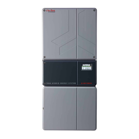
Quick Start Guide
True Hybrid Energy System
B
A
6.0"
(15.2 cm)
Hole
spacing
16"
(40.5 cm)
Hole spacing
Mounting Bracket
Ensure the mounting surface is strong enough to handle
three times the unit weight. Add plywood or other material
as necessary to strengthen the surface.
A Locate this horizontal slat at about eye level for easier display viewing.
B Do not locate the top of the bracket more than (about) 6' (183 cm)
off the floor. This ensures the SkyBox can be easily lifted onto the bracket.
Mark the placement of the bracket according to A and B, keeping in mind the
dimensions in the second drawing. These dimensions show the SkyBox overlap
(beyond the bracket) as well as the vertical measurements with respect to A. They
also add the required minimum clearances of 6" (15.2 cm) to SkyBox top and sides.
IMPORTANT:
No lower clearance is shown. In outdoor installations a 36" minimum clearance above the
ground or floor is required. The lower vertical measurement becomes 60.6" (153.9 cm) from A.
Weights:
Tools Needed:
o SkyBox: 87.7 lb (39.8 kg)
o 13 mm socket (torque) wrench
o BOS: 23.6 lb (10.7 kg)
o #2 Phillips (torque) driver
o Mounting Bracket: 4.6 lb (2.1 kg)
o Flat blade (torque) driver
WARNING: Burn Hazard
The heat sink (at the top rear of the product) may
reach temperatures greater than 70°C. Install this
product so that casual contact does not occur.
WARNING: Fire/Explosion Hazard
Do not place combustible or flammable materials
within 12 feet (3.7 m) of the equipment. This unit
employs mechanical relays and is not ignition-
protected. Fumes or spills from flammable materials
could be ignited by sparks.
WARNING: Personal Injury
Use safe lifting techniques and standard safety
equipment when working with this equipment.
NOTE: Additional information on
this product is available at
32"
www.outbackpower.com.
(81.3 cm)
For screen navigation, operation,
and troubleshooting, see the
SkyBox Overview Guide. For
C
programming and applications, see
28.6"
the SkyBox Programming Guide.
(72.6 cm)
D
Place the bracket so that
rails C and D are flush
A
with the surface.
24.6"
(62.5 cm)
SkyBox
9.4"
(23.9 cm)
BOS
(Balance of
System)
1½"
¾"
¾"
Left
Conduit Knockouts
(Underside of BOS)
o 6 mm Allen wrench
o Digital multimeter (DMM)
:
IMPORTANT
This document is for use by qualified personnel familiar with photovoltaic
(PV) systems and maximum power point tracking (MPPT) technology as
well as basic inverter functionality. Users of this document should meet
all local and governmental code requirements for licensing and training
for the installation of electrical power systems with AC and DC voltage
up to 600 volts. This product is only serviceable by qualified personnel.
Clearance and access requirements may vary by location. A 36" (91.4 cm)
clear space in front of the system for access is recommended. Consult
local electric code to confirm clearance and access requirements for the
specific location. If this product is installed or used in a manner other than
specified, the protection it provides may be impaired.
Fuses are not to exceed maximum output rating.
When installed outdoors, use only UL514B-compliant wet location or
rain-tight conduit hubs for entry into the enclosure.
See Specifications for instructions on system grounding and bonding.
¾"
¾"
¾"
¾"
Right
Advertisement
Table of Contents

Related Manuals for OutBack Power SKYBOX


Summary of Contents for OutBack Power SKYBOX
-
Page 1: Quick Start Guide
(beyond the bracket) as well as the vertical measurements with respect to A. They Various lithium-ion models Equipment grounding is required by Section 250 of the also add the required minimum clearances of 6" (15.2 cm) to SkyBox top and sides. National Electric Code (ANSI/NFPA 70) and Canadian IMPORTANT: Environmental Ratings: Electrical Code (C22.1). - Page 2 Permitted Sizes Torque Requirements Fire Hazard BOS into the SkyBox compartment, which opens with two Allen screws (K). If the SkyBox In-lb must be removed for service, the BOS and its wiring can remain. Some connections, such Before energizing, confirm that as communications, pass through the BOS to be made directly in the SkyBox.
- Page 3 Route the wires through channel OutBack’s ICS Plus or an equivalent NOTE: The SkyBox will not function unless one of these is installed. It will show a Rapid Shutdown fault. RSI system. See the RSI literature...
- Page 4 . Verify L2 by measuring from 19. On the Home screen, check the S O L A R tile (as shown to the right) and ensure it is operating normally. The SkyBox will connect to the PRODUCING Verify 240 Vac across the L...
Need help?
Do you have a question about the SKYBOX and is the answer not in the manual?
Questions and answers