
Related Manuals for OutBack Power FXR International Series


Summary of Contents for OutBack Power FXR International Series
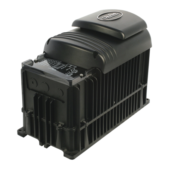
- Page 1 FXR International Series Inverter/Charger FXR2012E FXR2024E FXR2348E VFXR2612E VFXR3024E VFXR3048E Installation Manual...
- Page 2 About OutBack Power OutBack Power™ is a leader in advanced energy storage and conversion technology. OutBack Power products include true sine wave inverter/chargers, batteries, maximum power point tracking charge controllers, and system communication components, as well as circuit breakers, accessories, and assembled systems.
-
Page 3: Table Of Contents
Table of Contents Introduction ................. 5 Audience ........................... 5 Symbols Used ........................... 5 General Safety .......................... 5 Welcome to OutBack Power ..................... 6 Models ............................7 Inverter Model Names .......................... 7 Components and Accessories ......................7 Planning ..................9 ... - Page 4 Table of Contents List of Tables Table 1 Models ........................7 Table 2 Components and Accessories .................. 7 Table 3 Battery Bank Elements .................... 12 Table 4 Ground Conductor Size and Torque Requirements ..........20 Table 5 DC Conductor Size and Torque Requirements ............22 Table 6 ...
-
Page 5: Introduction
If this product is used in a manner not specified by FXR product literature, the product’s internal safety protection may be impaired. CAUTION: Equipment Damage Only use components or accessories recommended or sold by OutBack Power or its authorized agents. 900-0168-01-00 Rev D... -
Page 6: Welcome To Outback Power
Introduction Welcome to OutBack Power Thank you for purchasing the OutBack Power FXR Series Inverter/Charger. This product offers a complete power conversion system between batteries and AC power. It can provide backup power, sell power back to the utility grid, or provide complete stand-alone off-grid service. -
Page 7: Models
Introduction Models Vented FXR (VFXR) models have an internal fan and use outside air for cooling. On average, VFXR models have higher power ratings than FXR models due to their greater cooling capabilities. Sealed FXR models have an internal fan, but do not use outside air for cooling. To compensate, sealed models are also equipped with the OutBack Turbo Fan assembly, using external air to remove heat from the chassis. -
Page 8: Figure 2 Components
DC current shunt. AC Plate This plate is used for installations which do not utilize OutBack Power’s optional FLEXware conduit boxes. The knockouts are used to install strain relief for flexible cable. NOTE: This plate is not to be connected to conduit. -
Page 9: Planning
Planning Applications OutBack Power inverter/chargers are designed to use a battery bank to store energy. They work together with power from the utility grid or from renewable energy sources, such as photovoltaic (PV) modules, wind turbines, and other renewable sources. These sources charge the battery, which in turn is used by the inverter. -
Page 10: Input Modes
Planning Input Modes The FXR inverter has many modes of operation. See the FXR International Series Inverter/Charger Operator’s Manual for additional information on these modes, including reasons and considerations for using each mode. The modes determine how the inverter interacts with an AC source. Each mode has functions and priorities that are intended for a designated application. -
Page 11: Renewable Energy
Please note that Outback Power does not claim responsibility for any damage done by or to batteries that are deployed using the information found in this notice. -
Page 12: Table 3 Battery Bank Elements
These ten items are obtainable in different places, summarized in Table 3. Some of the information is specific to the site or application. Some can be obtained from the battery manufacturer. Information on products is available from OutBack Power or its dealers. A. Size of load:... - Page 13 Planning E. Conductor efficiency: Wire size and other factors Any losses are essentially amp-hour will waste power due to resistance and voltage drop. capacity that the system cannot use. Typical acceptable efficiency is 96 to 99%. The battery bank size can be F.
- Page 14 Planning EXAMPLE #1 A ÷ [E × F] 1000 ÷ (0.98 × 0.93) = 1097.2 W A. Backup loads: 1.0 kW (1000 W) 1 ÷ G 1097.2 ÷ 48 = 22.9 Adc B. Hours of use: 8 I = Ah ÷ hours 191.5 ÷...
-
Page 15: Generator
Planning Generator FXR inverters can accept power from a single-phase generator that delivers clean AC power in the range of voltage and frequency specified for that model. Inverters stacked for three-phase output can work with three-phase (230V/400Y) generators. The inverter/charger can provide a start signal to control an automatic start generator. If automatic generator starting is required, the generator must be an electric-start model with automatic choke. - Page 16 Planning NOTES: 900-0168-01-00 Rev D ©2015 EnerSys. All Rights Reserved.
-
Page 17: Installation
The unit has four mounting holes, one in each corner. (See Figure 4.) Use fasteners in all corners. Due to the variance in other methods, OutBack Power only endorses the use of FLEXware mounting products. Use M6 × 20 mm machine screws, one per corner, to attach the inverter to the plate. -
Page 18: Dimensions
Installation Dimensions Height with DCC 30.5 cm (12”) Length 41 cm (16.25”) Width 21 cm (8.25”) Height with Turbo 33 cm (13”) Placement of Mounting Fasteners Figure 4 Dimensions and Mounting 900-0168-01-00 Rev D ©2015 EnerSys. All Rights Reserved. -
Page 19: Terminals And Ports
Installation Terminals and Ports DC and AC DC TERMINALS GROUND TERMINALS These terminals connect to the battery cables and the DC system. These terminals connect to a See page 22 for instructions. grounding system for both batteries and AC. See page 20 for instructions. -
Page 20: Grounding
WARNING: Shock Hazard For all installations, the negative battery conductor should be bonded to the grounding system at only one point. If the OutBack Power GFDI is present, it can provide the bond. IMPORTANT: Most OutBack Power products are not designed for use in a positive-grounded system. If it is necessary to build a positive-grounded system with OutBack Power products, see the Positive Grounding applications note at www.outbackpower.com. -
Page 21: Figure 6 Dc Ground Lug
Installation The inverter’s DC ground is a box lug located next to the negative DC battery terminal. This lug accepts up to 70 mm² (1/0 AWG or 0.109 in²) wire. Local codes or regulations may require the DC ground to be run separately from the AC ground. Also, if present, it will be necessary to remove the DC Cover or Turbo Fan before making the ground connection. -
Page 22: Dc Wiring
The DC terminals must be encased in an enclosure to meet the requirements of some local or national codes. Table 5 contains OutBack Power’s recommendations for minimum safe cable sizes. Other codes may supersede these recommendations. Consult applicable codes for final size requirements. -
Page 23: Figure 8 Required Order Of Battery Cable Hardware
Installation To install DC cables and hardware: 1. Install all DC cables. Do not install hardware in a different order from Figure 8. The battery cable lug should be the first item installed on the stud. It should make solid contact with the mounting surface. Do not close the main DC disconnect until wiring is complete and the inverter system is prepared for commissioning. -
Page 24: Figure 10 Dc Cover Attachment
Installation DC Cover or Turbo Fan Attachment COVER ATTACHMENT FXR inverters are equipped with either the DC Cover or the Turbo Fan. To attach either cover, put the cover in place and insert a screw at each corner using a Phillips screwdriver. Make certain the red and black battery terminal covers are installed before attaching the cover. -
Page 25: Ac Wiring
Local or national codes may require the bond to be made at the main panel only. IMPORTANT: This page contains OutBack Power’s recommendations for minimum safe cable sizes. Other codes may supersede these recommendations. Consult applicable codes for final size requirements. -
Page 26: Ac Sources
Installation AC Sources The inverter has a single set of AC terminals which are intended to connect to a single source. It cannot be directly wired to more than one AC source at the same time. If multiple sources are used, it is usually required to have a selector switch that changes from one to the next. -
Page 27: On And Off Wiring
Installation ON and OFF Wiring The I jumper bridges two pins. NVERTER This jumper parallels the two I NVERTER terminals on the Control Wiring Terminal Block. If either connection is closed, this sets the inverter to On as long as the internal programming has not been set to Off with the system display. -
Page 28: Accessory Wiring
Installation Accessory Wiring The AC Wiring Compartment Board has ports for both the Remote Temperature Sensor (RTS) and the system display. The system display port is labeled M RTS cable RTS port (RJ11, 4-conductor, telephone) port See the Operator’s Manual for more information on System Display cable the RTS. -
Page 29: Figure 17 Aux Connections For Vent Fan (Example)
Installation In this example, the A directly drives a 12-volt vent fan. The + and – wires on the fan are connected to the A + and A – terminals. LED INDICATOR The A indicator illuminates when the A output becomes active. Figure 17 AUX Connections for Vent Fan (Example) In this example, the A... -
Page 30: Generator Control
Installation Generator Control The A terminals can provide a signal to control an automatic-start generator. The generator must be an electric-start model with automatic choke. It is recommended to have “two-wire” start capability. A two-wire-start generator is the simplest type, where the cranking and starting routine is automated. -
Page 31: Figure 19 Two-Wire Generator Start (Example)
Installation Two-Wire Start The 12 Vdc signal provided by the A output can be switched on and off to provide a start signal. It is possible to send a 12-Vdc signal directly to the generator. However, this should never be done if it connects the A output directly to the generator’s own battery. -
Page 32: Figure 20 Three-Wire Generator Start (Example) Ac Configurations
Atkinson Electronics (http://atkinsonelectronics.com) is one company that makes these kits. The Atkinson GSCM-Mini is intended to work with OutBack Power inverters. The drawing below is one example of a possible arrangement. Specific arrangements, relays, and other elements depend on the requirements of the installation and of the generator. -
Page 33: Ac Configurations
Installation AC Configurations Single-Inverter When installing an inverter AC system, the following rules must be observed. All overcurrent devices for must be sized for 30 Aac or less. All wiring must be sized for 30 Aac or more. All output circuit breakers must be sized appropriately for loads and inverter power. The AC input (generator or utility grid) must be a single-phase source of proper voltage and frequency. -
Page 34: Multiple-Inverter Ac Installations (Stacking)
Stacking allows all units to work together as a single system. Examples of stacking configurations include “parallel” and “three-phase” configurations. Stacking Connections Stacking requires an OutBack Power HUB10.3 communications manager and a system display. Make all interconnections between the products with CAT5 non-crossover cable. HUB10.3... - Page 35 FXR-class inverters cannot be stacked with legacy OutBack Power FX-class inverters. If more than one model class or series is stacked, any inverter different from the master will not invert or connect to an AC source.
-
Page 36: Stacking Configurations
Installation Stacking Configurations Parallel Stacking (Dual-Stack and Larger) In parallel stacking, two or more inverters create a single, common 230 Vac bus. The slave outputs are controlled directly by the master and cannot operate independently. All inverters share a common input (AC source) and run loads on a common output. Slave inverters can go into Silent mode when not in use. -
Page 37: Figure 24 Parallel Wiring (Four Inverters)
Installation AC Source LEGEND MATE3S (Utility Grid or AC Generator) Neutral HUB 10.3 Ground TBB = Terminal Bus Bar 10 9 8 7 6 5 4 3 2 1 MATE AC Conduit CAT5 Cables Neutral Hot L1 TBB Input Input Input Input Circuit... -
Page 38: Figure 25 Example Of Three-Phase Stacking Arrangement (Three Inverters)
Installation Three-Phase Stacking In three-phase stacking, inverters create three separate 230 Vac outputs in a wye configuration. The three outputs operate independently of each other. The inverters on one output cannot assist another. Several inverters can be installed in parallel to power all 230 Vac loads on that output. The output of each inverter is 120°... - Page 39 Installation When installing a three-phase inverter system, observe the following rules. Three-phase stacking requires both the system display and the communications manager. See the HUB10.3 literature for any required jumper configurations. The inverter that is mounted physically lowest is always master and is programmed as Master. Mounting below the other inverters allows the master to avoid heat buildup and remain relatively cool as it sees the greatest duty cycle.
-
Page 40: Figure 27 Three-Phase Wiring (Three Inverters)
Installation AC Source MATE3s3 (Utility Grid or AC Generator) AC Conduit Box 10 9 8 7 6 5 4 3 2 Neutral Phase B Phase C Phase A CAT5 Cables Input Input Input Circuit Circuit Circuit Breaker Breaker Breaker HUB/ HUB/ HUB/ Hot IN... -
Page 41: Figure 28 Power Save Levels And Loads
Installation Power Save IMPORTANT: In any system that features slave inverters, Power Save must be programmed before commissioning. Leaving the inverters at the factory default settings (or setting them incorrectly) will cause erratic system performance. See the FXR Series Inverter/Charger Operator’s Manual for a table of menu items and settings. - Page 42 Installation inverter can use any other port, beginning with port 2. In three-phase stacking, the port assignments are very specific, as illustrated in the HUB10.3 literature. Master Power Save Level appears on an inverter which is set as master (the default setting). The range of rank numbers is 0 to 10.
-
Page 43: Figure 29 Power Save Priority (Parallel)
Installation Master Slave 1 Slave 2 Slave 3 Port 1 Port 2 Port 3 Port 4 Master Power Save = 0 Slave Power Save = 2 Slave Power Save = 3 Slave Power Save = 1 <6 Aac 6 Aac 12 Aac 18 Aac 8 Aac... - Page 44 Installation NOTES: 900-0168-01-00 Rev D ©2015 EnerSys. All Rights Reserved.
-
Page 45: Functional Test
Commissioning Functional Test WARNING: Shock Hazard and Equipment Damage The inverter cover must be removed to perform these tests. The components are close together and carry hazardous voltages. Use appropriate care to avoid the risk of electric shock or equipment damage. It is highly recommended that all applicable steps be performed in the following order. -
Page 46: Figure 31 Ac Terminals
Commissioning Figure 31 AC Terminals 3. Turn on the inverter using the system display (or external switch, if installed). The inverter’s default condition is Off. Do not turn on any AC circuit breakers at this time. 4. Using a DVM or voltmeter, verify 230 Vac (or appropriate voltage) between the AC H and AC N terminals. -
Page 47: Powering Down
Commissioning After output testing is completed, perform the following steps: 5. Close the AC output circuit breakers. If AC bypass switches are present, place them in the normal (non-bypass) position. Do not connect an AC input source or close any AC input circuits. -
Page 48: Compliance
Inverters automatically update one at a time beginning with the highest port. Each requires about 5 minutes. Updates to the inverter’s internal programming are periodically available at the OutBack Power website www.outbackpower.com. -
Page 49: Definitions
Advanced Generator Start Inverter’s 12-volt auxiliary output Communications Multi-port device such as the HUB10.3; used for connecting multiple OutBack Power manager devices on a single remote display; essential for stacking inverters DC Cover; shields the DC terminal area on vented FX-class inverters... - Page 50 Commissioning Table 6 Terms and Definitions Term Definition Three-phase, 3-phase A type of utility electrical system with three “hot” lines, each 120° out of phase; each carries the nominal line voltage with respect to neutral; each carries voltage with respect to each other equaling the line voltage multiplied by 1.732 Transformer This inverter is provided with an internal isolation transformer with a class N insulation system...
-
Page 51: Index
Index Drawings AUX Connection .......... 29 General System Layout ......... 9 Generator Control ........30, 32 AC Plate ............. 7 Multiple AC Sources ........26 AC Terminals ......... 9, 19, 25 Parallel-Stacked System ....... 36, 37 AC Test Points ..........46 Single-Inverter System ...... - Page 52 Index IEC ............. 48, 49 QR Code ............5 Important Symbol ..........5 Ingress Protection (IP) ........17 Input Modes ............. 10 Ranks, Power Save ......... 41 Relative Humidity (RH) ........17 Remote Temperature Sensor (RTS) ..7, 19, 28 Jumper ............
- Page 53 Commissioning Wiring ............... 20 AC Connections ........... 25 AUX Connections ........28 Vent Fan ............29 DC Connections .......... 22 Vented Models ..........7, 17 Ground Connections ........20 Parallel Inverters .......... 36 Single Inverter ........32, 33 Stacking Warning Symbol ..........
- Page 54 This page intentionally left blank. 900-0168-01-00 Rev D...
- Page 55 This page intentionally left blank. 900-0168-01-00 Rev D...
- Page 56 World Headquarters EnerSys EMEA EnerSys Asia 2366 Bernville Road EH Europe GmbH 152 Beach Road Reading, PA 19605 USA Baarerstrasse 18 Gateway East Building #11-08 +1 610-208-1991 / +1 800-538-3627 6300 Zug Switzerland Singapore 189721 / +65 6508-1780 For more information visit www.enersys.com © 2021 EnerSys. All Rights Reserved. Trademarks and logos are the property of EnerSys and its affiliates unless otherwise noted.
Need help?
Do you have a question about the FXR International Series and is the answer not in the manual?
Questions and answers